NookBox WSS-4E-ZBS User manual
1NookBox Installation Guide Smart Scenario Switch WSS-4E-ZBS
Smart Scenario Switch
(WSS-4E-ZBS)
Installation Guide
2NookBox Installation Guide Smart Scenario Switch WSS-4E-ZBS
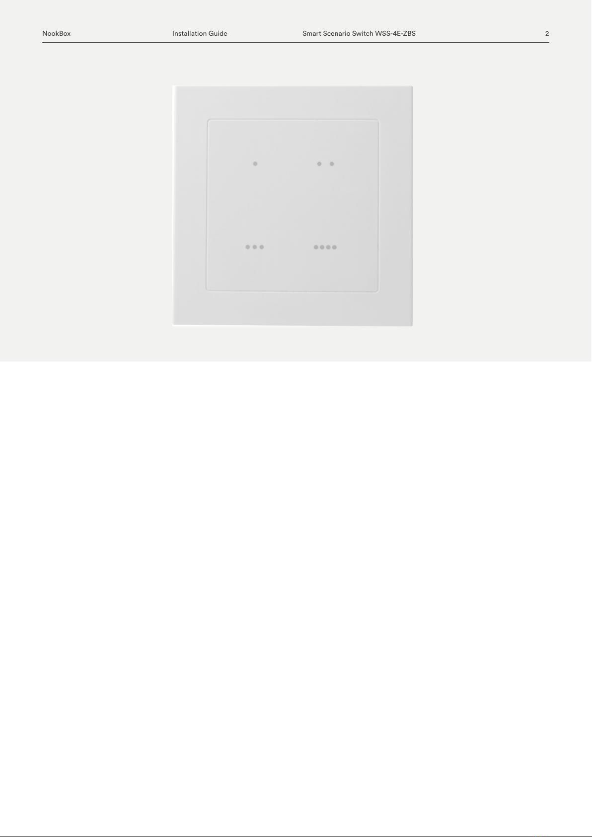
WSS-4E-ZBS is a ZigBee Four Touch Button Scenario Switch designed to control a group of
pre-programmed home automation devices by simply pressing the scenario touch buttons
under the same ZigBee network.
The Scenario Switch utilizes ZigBee technology for wireless signal transmission. ZigBee is a
wireless communication protocol that is reliable and has low power consumption and high
transmission eciency. Based on the IEEE802.15.4 standard, ZigBee allows a large amount of
devices to be included in a network and coordinated for data exchange and signal transmissi-
on.
The Scenario Switch serves as an end device in the ZigBee network. It can be included in the
ZigBee network to transmit signal upon activation, and can control any ZigBee device, but
cannot permit any other ZigBee device to join the network through the Scenario Switch.
The WSS-4E ZigBee Four Touch Button Scenario Switch includes the following models:
WSS-4E-ZBS
WSS-4E-ZBS-OTA
Smart Scenario Switch
(WSS-4E-ZBS)

3NookBox Installation Guide Smart Scenario Switch WSS-4E-ZBS
Device Introduction
1. Scenario LED
There are four Scenario LEDs, the LED will light up according to the correspondent Scenario touch button pressed.
When the Scenario Switch receives acknowledge from the Control Panel after a button press, it will ash once and emit a beep as indica-
tion.
If the LED ashes twice upon touch button press, it means the ZigBee control panel was unable to receive signal sent from Scenario Switch,
please check ZigBee connectivity.
2. Scenario Touch Button
The Scenario Switch has 4 scenario touch buttons:
• Touch Button 1
• • Touch Button 2
• • • Touch Button 3
• • • • Touch Button 4
3. Battery Compartment
4. Function Button
-Press and hold for 10 seconds to reset.
5. ZigBee LED (Red)
Red LED lights up in the following situations:
- Flashes once:
When sending control, resetting, or learning signal.
When the Scenario Switch receives acknowledgement from the Control Panel after a button press.
- Flashes twice:
The Scenario Switch has successfully joined a ZigBee network.
6. Function Button Hole

4NookBox Installation Guide Smart Scenario Switch WSS-4E-ZBS
Features
Battery and Low Battery Detection
The Scenario Switch uses two 1.5V AA Alkaline batteries as its power source. The Scenario Switch feature Low Battery Detection function.
When the battery voltage is low, the Scenario Switch will transmit Low Battery signal to the ZigBee network coordinator.
Scenario
When a Scenario Touch Button is pressed, the Scenario Switch will send a signal to the Control Panel to activate the correspondent scenario
(see Control Panel for details).
ZigBee Network Setup
ZigBee Device Guideline
The IR Remote Control is a wireless communication protocol that is reliable and has low power consumption and high transmission eciency.
Based on the IEEE802.15.4 standard, ZigBee allows a large amount of devices to be included in a network and coordinated for data exchange
and signal transmission.
Due to the fundamental structure of ZigBee network, ZigBee device will actively seek and join network after powering on. Since performing a
task in connecting network may consume some power, it is required to follow the instructions to avoid draining battery of a ZigBee device.
- Ensure the ZigBee network router/coordinator is powered on before inserting battery into ZigBee device.
- Ensure the ZigBee network router/coordinator is powered on and in range while ZigBee device is in use.
-Do not remove a ZigBee device from the ZigBee network router or coordinator without removing the battery from a ZigBee device.
Joining the ZigBee Network
As a ZigBee device, the IR Remote Control needs to join a ZigBee network to receive command from ZigBee network coordinator to transmit
IR signal. Please follow the steps bellow to join the IR Remote Control into the ZigBee network.
1. Insert batteries to power on the IR Remote Control.
2. Press and hold the ZigBee button for 10 seconds, then release it to join the network. Please make sure the permit-join feature on the
router or coordinator of your ZigBee network is enabled.
3. After joining the ZigBee network, the IR Remote Control will be registered in the security system in the network automatically. Please
check the security system control panel or CIE (Control and Indicating Equipment) to conrm if joining and registration is successful.
4. If the IR Remote Control successfully joins the ZigBee network, the ZigBee LED will ash twice to indicate.
5. After joining the ZigBee network, if the IR Remote Control loses connection to current ZigBee network, the ZigBee LED indicator will
ash every 20 minutes. Please check the ZigBee network condition and the IR Remote Control signal range to correct the situation.
Removing Device from ZigBee Network (Factory Reset)
To remove the device from current ZigBee network, the IR Remote Control must be put to Factory Reset to complete device removal. Factory
Reset function will clear the IR Remote Control of its stored setting information and prompt the device to search for new ZigBee network.
Before removing device, make sure the device is within current ZigBee network signal range
1. Delete the IR Remote Control from current control panel / CIE.
2. Press and hold the function button for 10 seconds, then release the button to reset device.
3. Upon reset, the IR Remote Control will clear current ZigBee network setting and transmit signal to ZigBee coordinator to remove
itself from current ZigBee network. It will then actively search for available ZigBee network again and join the network automatically.
OTA Firmware Upgrade
The device supports OTA rmware upgrade feature via ZigBee network, which can be initiated from the ZigBee network coordinator.
Follow steps below to perform OTA rmware upgrade.
1. You have to access your ZigBee Coordinator to perform the rmware upgrade on the air.
2. On the conguration webpage, select the device that you wish to upgrade and select the new ZigBee
rmware provided. Please refer to ZigBee Coordinator User Manual for detail.
3. Press OK to start upgrading process, please do not perform any other actions, or power down the panel.
4. The length of an upgrade will take approximately 20 to 30 minutes. Please note that the duration may
vary based on le size or distance between your accessory and coordinator.
5. Wait for rmware to complete update. When the progress reaches 100%, the Device will reset
automatically. You can also refresh the webpage again to ensure if the Device rmware is successfully
updated with the newest version displayed.

5NookBox Installation Guide Smart Scenario Switch WSS-4E-ZBS
Installation
The Scenario Switch is designed to be mounted on a at surface with xing screws.
The base has 3 knockouts, where the plastic is thinner, for mounting purpose.
1. Remove the cover by using a screwdriver.
2. Break through the appropriate knockouts on the base.
3. Using the holes as a template, drill holes in the surface.
4. Screw the base into the surface.
5. Replace the cover back onto the base and secure it by tightening the xing screw.

6NookBox Installation Guide Smart Scenario Switch WSS-4E-ZBS

7NookBox Installation Guide Smart Scenario Switch WSS-4E-ZBS
For more information visit:
www.getnookbox.com
Table of contents
Other NookBox Switch manuals


Popular Switch manuals by other brands

LightwaveRF
LightwaveRF LW934 instruction manual

Micro Innovations
Micro Innovations USB455P Quick installation guide

ADTRAN
ADTRAN Total Access Octal DS1 IMA Specification sheet

BT
BT Home Hub quick start guide

HYDROMETER
HYDROMETER IZAR CENTER 60 Installation

Ubiquiti
Ubiquiti EdgeSwitch 48 LITE quick start guide

Presentation Switchers
Presentation Switchers PS100 quick start

DeDietrich
DeDietrich Gas 310 Eco Series installation manual

Cisco
Cisco Catalyst 3560E-24TD Product support bulletin

CYP
CYP CVSD-41ARN Operation manuals

Comm-Tec
Comm-Tec UP-82TS user manual

Planet Networking & Communication
Planet Networking & Communication XGS-6350-24X4C Quick installation guide


