manuals.online logo
Brands
  1. Home
  2. •
  3. Brands
  4. •
  5. IFM Electronic
  6. •
  7. Switch
  8. •
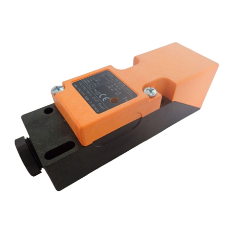
  9. IFM Electronic efector100 GG507S User manual

IFM Electronic efector100 GG507S User manual

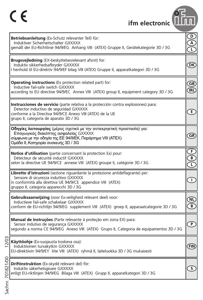
Bestimmungsgemäße Verwendung
Der Näherungsschalter erfaßt berührungslos Metalle und meldet sie
durch ein Schaltsignal.
Nennschaltabstand (Sn) siehe Typbezeichnung auf dem Geräteaufkle-
ber; Arbeitsbereich (Sa) 0 ... 0,81 x Sn; (Werte nach Norm-Messung auf
ST 37; bei anderen Metallen kürzer).
Elektrischer Anschluß
Schalten Sie die Anlage spannungsfrei. Schließen Sie das Gerät
nach den Angaben auf dem Typenschild an.
Sie können das Gerät als Schließer ( ) oder als Öffner ( )
betreiben.
Montage
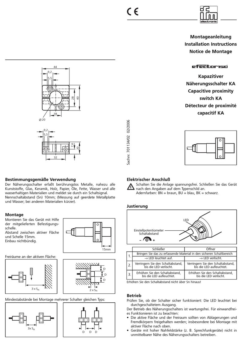
Bauen Sie das Gerät mit Hilfe
einer Montagehalterung ein und
justieren Sie es.
Es ist richtig justiert, wenn die
rote LED nicht leuchtet.
Sichern Sie es mit den mitgeliefer-
ten Muttern gegen Loslösen.
Einbau nichtbündig.
Freiräume an der aktiven Fläche bei Einbau in Metall:
Mindestabstände bei Montage mehrerer Schalter gleichen Typs:
Betrieb
Prüfen Sie, ob der Schalter sicher funktioniert. Anzeige durch 2 LEDs:
• Die gelbe LED leuchtet bei durchgeschaltetem Ausgang.
• Die rote LED leuchtet bei einem Justierfehler.
Der Betrieb des Näherungsschalters ist wartungsfrei.
Für einwandfreies Funktionieren ist zu beachten:
• Die aktive Fläche und der Freiraum sollten von metallischen Ablage-
rungen und Fremdkörpern freigehalten werden; insbesondere bei
Montage mit aktiver Fläche nach oben.
• EMV: Das Gerät erfüllt die Anforderungen nach EN 60947-5-2.
Montageanleitung
Installation Instructions
Notice de Montage
Induktiver
Näherungsschalter
mit Montagehilfe
Inductive proximitiy
switch with setting aid
Détecteur de proximité
inductif avec aide au
réglage
Sachnr. 701253 / 00 01 / 98 Technische Änderungen behalten wir uns ohne vorherige Ankündigung vor. Papier chlorfrei
R
3 x Sn
8 x Sn
2 x DD D
D
D
D
2 x Sn
LED gelb —
LED rot — —
Schaltfunktion
Kein Objekt im Arbeitsbereich.
LED gelb —
LED rot — — Objekt sicher erkannt.
LED gelb —
LED rot
Unsichere Objekterkennung
(justieren Sie das Gerät neu).
LED gelb —
LED rot
Unsichere Funktion: Das Gerät ist durch
Metallablagerungen vorbedämpft oder
die Freiräume an der aktiven Fläche
sind zu gering;
(reinigen Sie die aktive Fläche oder
justieren Sie das Gerät neu).
LED gelb
LED rot
Function and features
This proximity switch detects metals without contact and indicates
their presence by providing a switched signal.
The nominal sensing range (Sn) can be seen in the type designation on
the type label on the unit; operating distance (Sa) 0 ... 0,81 x Sn;
(values based on standard measurement with mild steel; a shorter
sensing range for other metals).
Electrical connection
Disconnect power before connecting the proximity switch.
Connection strictly to the indications on the type label.
The unit can be used as normally open ( ) or as normally
closed ( ).
Installation
Mounting by means of a mount-
ing device.
Adjust the unit. Adjustment is
correct when the red LED does
not light.
Secure by means of the nuts pro-
vided so that it cannot work
loose.
Non-flush installation.
Open space around the sensing face when mounted in metal:
Fonctionnement et caractéristiques
Ce détecteur de proximité détecte les métaux sans contact et indique
leur présence par un signal de commutation.
Pour la portée nominale (Sn) voir la désignation sur l’étiquette, portée
de travail (Sa) 0 ... 0,81 x Sn; (valeurs définies par mesure selon les
normes avec acier 37; en cas d’autres métaux portée inférieure à Sn).
Raccordement électrique
Mettre l’installation hors tension avant le raccordement du
détecteur de proximité.
Raccordement strictement selon les indications de l’étiquette.
L'appareil peut être utilisé en normalement ouvert ( ) ou en
normalement fermé ( ).
Montage
Montage à l’aide d’une flasque
de fixation.
Ajuster l'appareil. Le réglage est
correct lorsque la LED rouge
n'est pas allumée.
Utiliser les écrous fournis pour
une fixation optimale.
Montage non encastré.
Zone de dégagement autour de la face active pour montage sur bâti
métallique:
Distances minimales lorsque plusieurs détecteurs de la même version
sont montés:
Fonctionnement
Vérifier le bon fonctionnement du détecteur. Indication par LED:
• La LED rouge est allumée lorsque la sortie est commutée.
• La LED jaune est allumée en cas de réglage incorrect.
Pour un bon fonctionnement il faut respecter les indications suivantes:
•La face active et l’espace libre doivent être dégagés de toute présen-
ce de dépôts et de corps étrangers métalliques, notamment en cas
de montage avec la face active vers le haut.
•CEM: L’appareil est en harmonie avec les exigences selon
EN 60947-5-2.
Minimum distance when several switches of the same type are mounted:
Operation
Check the safe functioning of the switch. Display by LEDs:
• The yellow LED is lit when the output is switched.
• The red LED is lit in case of faulty adjustment.
The operation of the proximity switch is maintenance-free.
For perfect functioning make sure that:
•the sensing face and the open space are kept free of metal deposits
and foreign bodies, particularly for installation with the sensing face
facing upwards;
• EMC: The unit conforms to the requirements of EN 60947-5-2.
3 x Sn
8 x Sn
2 x DD D
D
D
D
2 x Sn
3 x Sn
8 x Sn
2 x DD D
D
D
D
2 x Sn
LED yellow
LED red
LED jaune
LED rouge
LED yellow —
LED red — —
output function
No object in the detection range.
LED yellow —
LED red — — Safe detection of the object.
LED yellow —
LED red
Unsafe detection of the object
(readjust the unit).
LED yellow —
LED red
Uncertain function: predamping of the
unit by metal deposits or insufficient
open space around the active face;
(clean the active face
or readjust the unit).
LED jaune —
LED rouge — —
sortie
Pas d'objet dans la zone de détection.
LED jaune —
LED rouge — — Objet dans la zone de détection sûre.
LED jaune —
LED rouge
Objet dans la zone de détection
non sûre
(ajuster l'appareil de nouveau).
LED jaune —
LED rouge
Fonctionnement non sûr: l'appareil est
préamorti par des dépôts métalliques ou
les espaces libres autour de la face
active sont trop petits:
(nettoyer la face active
ou ajuster l'appareil de nouveau).

Other manuals for efector100 GG507S

3

This manual suits for next models

1

Other IFM Electronic Switch manuals

IFM Electronic Efector 160 LI5045 User manual

IFM Electronic

IFM Electronic Efector 160 LI5045 User manual

IFM Electronic Efector110 User manual

IFM Electronic

IFM Electronic Efector110 User manual

IFM Electronic Efector 150 KNM User manual

IFM Electronic

IFM Electronic Efector 150 KNM User manual

IFM Electronic efector100  IME User manual

IFM Electronic

IFM Electronic efector100 IME User manual

IFM Electronic efector 150 KA User manual

IFM Electronic

IFM Electronic efector 150 KA User manual

IFM Electronic NAMUR KI-2015-N User manual

IFM Electronic

IFM Electronic NAMUR KI-2015-N User manual

IFM Electronic ZB0052 User manual

IFM Electronic

IFM Electronic ZB0052 User manual

IFM Electronic G Series User manual

IFM Electronic

IFM Electronic G Series User manual

IFM Electronic Efector 160 LI2 User manual

IFM Electronic

IFM Electronic Efector 160 LI2 User manual

IFM Electronic AL3100 User manual

IFM Electronic

IFM Electronic AL3100 User manual

IFM Electronic efector 150 User manual

IFM Electronic

IFM Electronic efector 150 User manual

IFM Electronic ecomat100 GI5002 User manual

IFM Electronic

IFM Electronic ecomat100 GI5002 User manual

IFM Electronic efector160 LI5 Series User manual

IFM Electronic

IFM Electronic efector160 LI5 Series User manual

IFM Electronic Efector 150 KG User manual

IFM Electronic

IFM Electronic Efector 150 KG User manual

IFM Electronic ZB0050 User manual

IFM Electronic

IFM Electronic ZB0050 User manual

Popular Switch manuals by other brands

Monoprice HDX-201E user manual

Monoprice

Monoprice HDX-201E user manual

KSB AMTROBOX Series General information

KSB

KSB AMTROBOX Series General information

Avaya M770 user guide

Avaya

Avaya M770 user guide

Comtech EF Data SMS-758 Installation and operation manual

Comtech EF Data

Comtech EF Data SMS-758 Installation and operation manual

PCB Piezotronics IMI SENSORS 691B47 Installation and operating manual

PCB Piezotronics

PCB Piezotronics IMI SENSORS 691B47 Installation and operating manual

Icy Box IB-HUB1701-U3 Quick installation guide

Icy Box

Icy Box IB-HUB1701-U3 Quick installation guide

Weidmuller IE-SW-IP67-5M12 Hardware installation guide

Weidmuller

Weidmuller IE-SW-IP67-5M12 Hardware installation guide

Indu-Sol PROmesh U16 Quick start user guide

Indu-Sol

Indu-Sol PROmesh U16 Quick start user guide

Conrad Electronic 64 64 43 operating instructions

Conrad Electronic

Conrad Electronic 64 64 43 operating instructions

Keithley 708 instruction manual

Keithley

Keithley 708 instruction manual

Barksdale D1T operating instructions

Barksdale

Barksdale D1T operating instructions

ANTAIRA LMX-1600G Series Quick installation guide

ANTAIRA

ANTAIRA LMX-1600G Series Quick installation guide

M-system 18KYV instruction manual

M-system

M-system 18KYV instruction manual

Asante FriendlyNet FH100TX16 user manual

Asante

Asante FriendlyNet FH100TX16 user manual

Cisco Nexus 3548 series Command reference

Cisco

Cisco Nexus 3548 series Command reference

Pickering 40-193 user manual

Pickering

Pickering 40-193 user manual

Edimax ES-5224RS+ manual

Edimax

Edimax ES-5224RS+ manual

AVCOMM 608TX Quick installation guide

AVCOMM

AVCOMM 608TX Quick installation guide

manuals.online logo
manuals.online logoBrands
  • About & Mission
  • Contact us
  • Privacy Policy
  • Terms and Conditions

Copyright 2025 Manuals.Online. All Rights Reserved.