Norac UC5 Topcon X30 User manual

1
PN 2006019–ENG Rev. I
Norac UC5
Norac Unlock
The Features Tab is where you can enter unlock
codes. Unlock codes are unique to the serial
number of each display and the feature
registration number. You must supply these
numbers to your dealer when purchasing any
unlock codes. Press to enter the unlock
code and press to enable the feature.
Norac UC5 can be used with or without an unlock but how you setup and run the system differs depending on whether
the system is locked or unlocked and using CAN A or CAN B.
Create Configuration
To create a configuration, make the following button presses to start the Configuration Wizard and then follow the
instructions given on the display. The configuration can be started in two places:
OR
OR
The wizard will guide you through the process of selecting or creating a vehicle, implement and controllers.
Your Operating Configuration will then be viewable when you start a new Field Operation with the Field Operation Wizard.
Setup Configuration
Locked UnLocked
CAN A No Functionality Setup using Ag Leader Screens
Operate using Ag Leader Screens
CAN B Setup using Universal Terminal Screens
Operate using Universal Terminal Screens
Setup using Universal Terminal Screens
Operate using Ag Leader Screens
Features
Consule Setup
General Display Features AgFiniti Advanced
Hardi Sprayer
ISOBUS
Norac UC Interface
Feature
Automatic Swath
Multiple Product
Feature Description:
Unlock
Enabled
Enabled
Enabled
Enabled
Enabled
Status
Configuration
Application
Planting
Configuration
Select Your Specific
Configuration
NORAC UC5

2
A. Norac Devices drop-down menu—The
drop down menu shows the devices
communicating on the NORAC UC5 CAN
Bus along with the serial number of each
device. The Firmware Version and
Hardware Revisions of your NORAC UC5
devices are shown underneath.
•Automatic Setup—Automatic Setup
walks through a series of steps that
configures the NORAC UC5 electronics to
the sprayer hydraulic functions. You must
perform an Automatic Setup routine after
the NORAC UC5 system is installed. The
following items are configured during an
Automatic Setup routine:
•Sprayer Make and Model
•Input module wiring and
configuration
•Number of sensors and location
•Sensor zero point
•Valve deadzone and gain values.
÷NOTE!: For detailed Automatic Setup information, see the NORAC UC5 manual.
•Sensors and Valve Drivers—Opens the Sensor and Valve Driver Settings screen (for more detail see the next page).
•Boom Control Module—Turn motion detection on/off, choose source as GPS or AUX.
•Advanced Settings—For use by a technician.
•Retune—From time to time it may be necessary to recalibrate (Retune) the UC5 electronics to your sprayer’s
hydraulics. Examples of such times are:
•When a hydraulic solenoid valve is changed.
•When the hydraulic pump is changed or adjusted.
•When the normal working temperature of the hydraulic oil has shifted significantly from when the system was
previously calibrated.
If you are running a pull type sprayer and use different tractors to operate the sprayer, you should run the Retune procedure
each time the tractor is changed. If you have a flow control for the boom hydraulics, set it prior to tuning. If you change the
flow setting by more than 20 percent, you should Retune.
Norac UC5
Automatic
Setup
Firmware Version
Hardware Version
Sprayer Configuration: Sprayer Model
Unknown
Unknown
Controller #300
Sensors and
Valve Drivers
Boom Control
Module
Advanced
Settings
Retune
Norac UC5
3
PN 2006019–ENG Rev. I
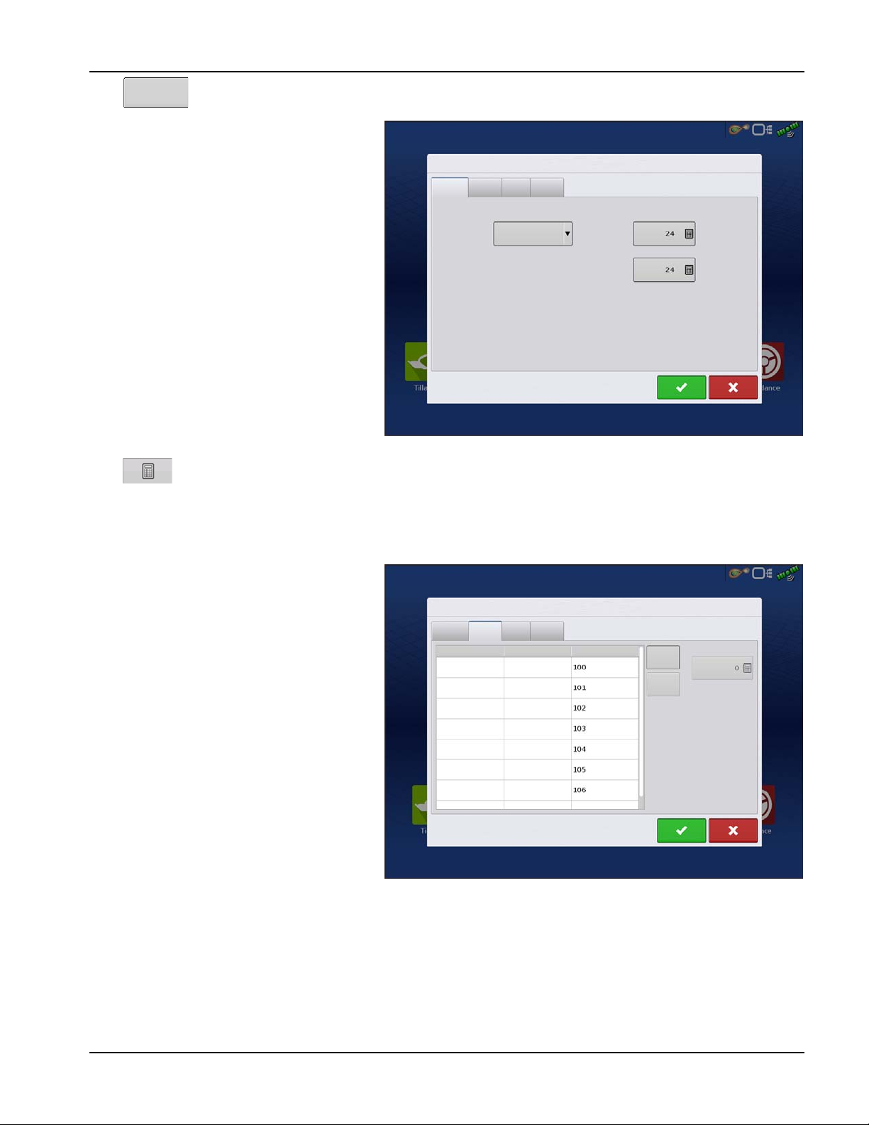
Press to open the Norac UC5 Setup.
General Tab
Minimum Height Mode includes three
selections:
•Absolute—no sensors are allowed to
move closer to the target than the
minimum height setting.
•Relative—no sensors are allowed to move
closer to the target than the distance of the
target height minus the minimum height
setting.
•Disabled—Disables the minimum height
mode.
÷NOTE!: “ Target” refers to the ground in Soil
Mode, and the crop canopy in Crop
Mode.
•Minimum Height—If desired, press
to adjust the following settings.
•Soil Mode - The minimum height setting when operating in Soil Mode.
•Crop Mode - The minimum height setting when operating in Crop Mode. Also, consult the NORAC UC5
manual for more information.
Sensor Tab—List of each sensor type and serial
number, add or remove a sensor, input nozzle
height.
Sensors and
Valve Drivers
Norac UC5 Setup
General Sensor Valve Switch
Minimum Height
Minimum Height Mode Soil Mode
Crop Mode
Disabled
Norac UC5 Setup
General Sensor Valve Switch
Height
Height
Height
Height
Height
Roll
Roll
Type Sensor
Left Outer
Main Lift
Right Outer
Left Inner
Right Inner
Boom Frame
Intermediate
Frame
Serial Number Add
Remove
Nozzle Height

4
Valve Tab—List of each valve, type, serial
number, and output. Add or Remove a valve, test
valve, adjust gain and deadzone.
Switch Tab—List of switches, functions, serial
numbers, and input. Add or Remove a switch.
Load Configuration
Press the Application button from the home screen. This will take you through the steps needed to load a
configuration.
Engage button
If the NORAC UC5 Boom Height Control is included in your Operating Configuration, then the NORAC
Engage button appears on the display’s Task Bar. The Engage button enables boom height control. This
button is green when the NORAC UC5 system is engaged; and grey when disengaged. Press on this button
to engage and disengage the NORAC UC5 Boom Height Control.
This button can be used to toggle back and forth between Automatic Mode and Manual Mode.
•When you enable Automatic Mode, this button turns green and the display beeps three times.
Norac UC5 Setup
General Sensor Valve Switch
Left Up
Type Serial Output Add
Remove
Valve
Gain
Deadzone
Test
Valve
Left Down
Right Up
Bypass
Right Down
Main Up
Main Down
Valve
Valve
Valve
Valve
Valve
Valve
Valve
Norac UC5 Setup
General Sensor Valve Switch
Function Serial Input Add
Remove
Left Up
Left Down
Right Up
Right Down
Main Up
Main Down
Norac UC5
5
PN 2006019–ENG Rev. I
•When you disable Automatic Mode on any part of the boom and the display switches to Manual Mode, this button
turns white and the display beeps twice. If less than the full boom remains in Manual Mode, the display will continue
beeping twice every three seconds.
Boom Height Control Options Button
At the center of the Map screen’s Equipment
Tab, the Boom Height Control Options button
displays data on NORAC UC5 Run Time
performance.
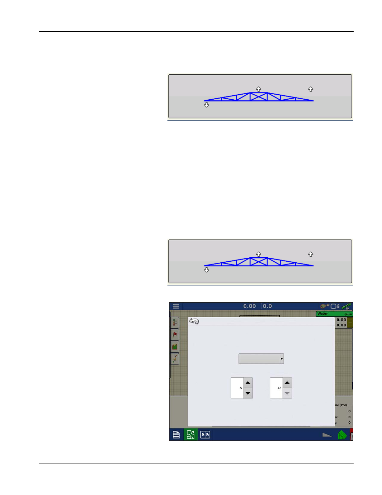
•The Boom Icon appears as blue when in
Automatic Mode; and black when in
Manual Mode. The right, left and center
sections appear independently on this icon. Press the Boom Height Control Options button to open the Boom
Height Control Options screen.
•The white arrows indicate the direction that the boom section is being commanded to move. The arrows shown
around the boom appear either 1) In Automatic Mode, or 2) When the boom is in Manual Mode and the boom is
moved by the operator.
•Mode—Indicates whether the Boom is in Crop Mode, Soil Mode, or Hybrid Mode.
•Target Height—The desired boom height above the ground (for Soil Mode), or the crop canopy (for Crop Mode).
•Sensitivity—Adjusts the boom response. Higher values make the height control more responsive.
•Distance Between Boom and Target—The numbers that appear below the Boom Icon show the distance
between the boom section and the target.
•Temperature—Shows the measurement of the outside ambient air temperature.
Boom Height Control
Options Screen
Pressing the Boom Height Control Options
button opens the Boom Height Control
Options screen.
At this screen, you can adjust the boom’s Mode,
Sensitivity and Target Height.
•Mode—The drop-down menu is where
you can choose one of three modes:
A. Soil Mode—the UC5 controls
boom height relative to the distance
from the soil.
B. Crop Mode—the UC5 controls
boom height relative to distance
from the crop canopy.
C. Hybrid Mode—The UC5 controls
boom height using a combination
of soil and crop readings. For
detailed Hybrid Mode information,
see the Norac UC5 manual.
Mode: Crop Target Height: 12 in Sensitivity: 5
15.9 8.4 8.4 50 F
Mode: Crop Target Height: 12 in Sensitivity: 5
15.9 8.4 8.4 50 F
Boom Height Control Options
Crop Mode
Sensitivity Target Height
Other manuals for UC5 Topcon X30
55
Table of contents


