NORBAIN HIGH RESOLUTION 1/3" CCD COLOUR & DAY /... Service manual
HIGH RESOLUTION 1/3" CCD BLACK & WHITE
HIGH RESOLUTION 1/3" CCD COLOUR & DAY / NIGHT
VISTA 3-AXIS VANDAL RESISTANT
DOME CAMERAS
Please read this manual thoroughly before use, and keep it handy for future reference.
Installation & Instruction Manual

LIMITATION OF LIABILITY
THE INFORMATION IN THIS PUBLICATION IS BELIEVED TO BE ACCURATE IN
ALL RESPECTS, HOWEVER, WE CANNOT ASSUME RESPONSIBILITY FOR ANY
CONSEQUENCES RESULTING FROM THE USE THEREOF. THE INFORMATION
CONTAINED HEREIN IS SUBJECT TO CHANGE WITHOUT NOTICE. REVISIONS
OR NEW EDITIONS TO THIS PUBLICATION MAY BE ISSUED TO INCORPORATE
SUCH CHANGES.
WARNING
TO REDUCE THE RISK OF FIRE OR ELECTRIC SHOCK, DO NOT
EXPOSE THIS PRODUCT TO RAIN OR MOISTURE. DO NOT INSERT
ANY METALLIC OBJECT THROUGH THE VENTILATION GRILLS
OR OTHER OPENINGS ON THE EQUIPMENT.
CAUTION
C A U T I O NC A U T I O N
RISK OF ELECTRIC SHOCK
DO NOT OPEN
CAUTION: TO REDUCE THE RISK OF ELECTRIC SHOCK,
DO NOT REMOVE COVER(OR BACK).
NO USER-SERVICEABLE PARTS INSIDE.
REFER SERVICING TO QUALIFIED SERVICE PERSONNEL.
EXPLANATION OF GRAPHICAL SYMBOLS
The lightning flash with arrowhead symbol, within an
equilateral triangle, is intended to alert the user to the
presence of uninsulated "dangerous voltage" within the
product's enclosure that may be of sufficient magnitude to
constitute a risk of electric s hoc k to p ers o ns.
The exclamation point within an equilateral triangle is
intended to alert the user to the presence of important
operating and maintenance (servicing) instructions in the
literature accompanying the product.

WARNING :
THIS IS A CLASS A PRODUCT. IN A DOMESTIC ENVIRONMENT
THIS PRODUCT MAY CAUSE RADIO INTERFERENCE IN WHICH
CASE THE USER MAY BE REQUIRED TO TAKE ADEQUATE
MEASURES.
CE COMPLIANCE STATEMENT
V

IMPORTANT SAFEGUARDS
1. Read these instructions.
2. Keep these instructions.
3. Heed all warnings.
4. Follow all instructions.
5. Do not use this apparatus near water.
6. Clean only with dry cloth.
7. Do not block any ventilation openings. Install in accordance with the
manufacturer's instructions..
8. Do not install near any heat sources such as radiators, heat
registers, stoves, or other apparatus (including amplifiers) that
product heat..
9. Do not defeat the safety purpose of the polarized or grounding-type plug. A
polarized plug has two blades with one wider than the other.
A grounding type plug has two blades and a third grounding prong.
The wide blade or the third prong are provided for your safety. If the provided
plug does not fit into your outlet, consult an electrician for replacement of the
obsolete outlet.
10. Protect the power cord from being walked on or pinched
particularly at plugs, convenience receptacles, and the point where thy exit from
the apparatus.
11. Only use attachments/accessories specified by the manufacturer.
12. Unplug this apparatus during lightning storms or when unused for long periods
of time.
13. Refer all servicing to qualified service personnel. Servicing is
required when the apparatus has been damaged in any way, such as power-
supply cord or plug is damaged, liquid has been spilled or objects have fallen
into the apparatus, the apparatus has been exposed to rain or moisture, does
not operate normally, or has been dropped.
14. CAUTION - THESE SERVICING INSTRUCTIONS ARE FOR USE BY
QUALIFIED SERVICE PERSONNEL ONLY. TO REDUCE THE RISK OF
ELECTRIC SHOCK DO NOT PERFORM ANY SERVICING OTHER THAN
THAT CONTAINED IN THE OPERATING INSTRUCTIONS UNLESS YOU ARE
QUALIFIED TO DO SO.
15. Use Certified/Listed Class 2 power supply transformer only.
V

INTRODUCTION
High-performance 1/3" SONY DSP colour Exview HAD CCD technology
NTSC: 480 lines(Colour), 570 lines(B/W) of resolution(High)
PAL 480 lines(Colour), 570 lines(B/W) of resolution(High)
0.8lux(Colour), 0.08lux(B/W), F1.2 Sensitivity(High)
0.5lux(Colour), 0.04lux(B/W), F1.2 Sensitivity(High/ex-view)
Auto electronic shutter [1/60(1/50) ~ 1/100,000] and manual electronic shutter
modes
1/3" CCD Colour Image Sensor:
This is a professional level camera chip which achieves a very high quality
picture.
4-9mm Vari-focal Lens,
4-9mm vari-focal DC Auto Iris Lens
4-9mm vari-focal Day&Night DC Auto Iris Lens
3.6mm F3.8 fixd lris Lens
Allows a large area to be monitored from a single camera.
Flicker less, BLC, D/N Conversion(Colour/BW), AGC, D&N(Auto/Manual), Sync
adjustments
12VDC or 24VAC(B/W camera to 12VDC only)
If use DC 12V power adapter, Use Certified/Listed Class 2 power supply
transformer only.
Use Certified/Listed Class 2 power transformer only.
2.6-6mm vari-focal DC Auto Iris Lens
The 1/3" DSP colour security camera provides SONY, true-colour images especially
for closed-circuit television (CCTV) and security surveillance applications.
FEATURES:
- 1 -

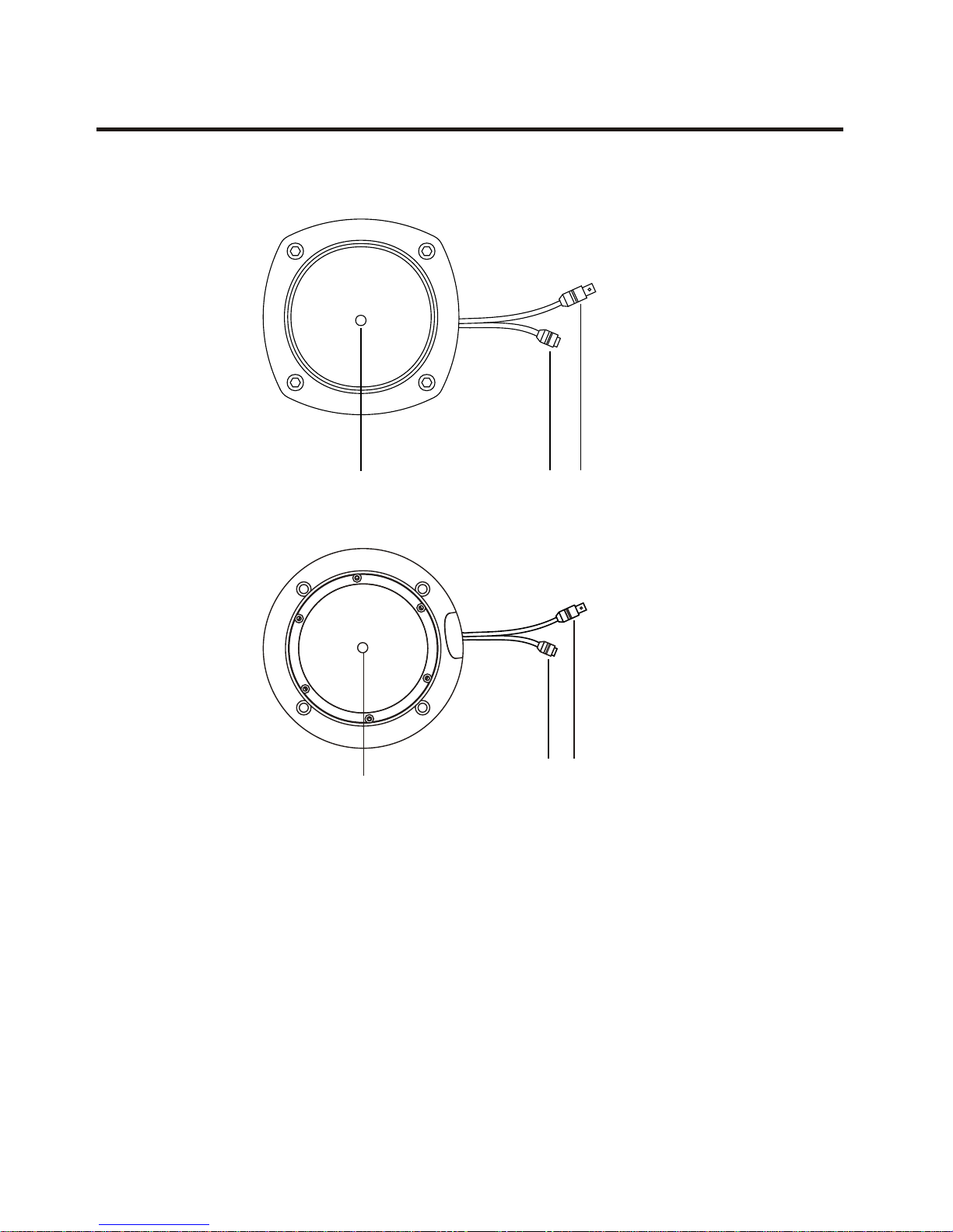
COLOUR CAMERA CONNECTIONS
- 2 -
REMINDER:
Never aim the camera directly into the sun.
1. Lens : Allows a wide area to be monitored.
2. Power : 24VAC input / 12VDC input
3. Video : BNC connector used to connect the camera to a monitor, switcher, etc.
2
13
1
23
POWER
Use Certified/Listed Class 2 power supply transformer only.
1. Lens : 3.6mm Fixed lens (Wall Mount Version only),
2.6-6
4-9mm DC Varifocal lens for wide area monitoring.
2. Power : 12VDC power (2.1mm socket centre +ve)
3. Video : BNC video output connects to monitor or
accessory equipment.
mm DC Varifocal lens for wide area monitoring
2
13
1
23
B/W CAMERA CONNECTIONS
- 3 -

- 4 -
TOP
TOP
TOP
Note : Arrow mark indicates the top of the camera image.

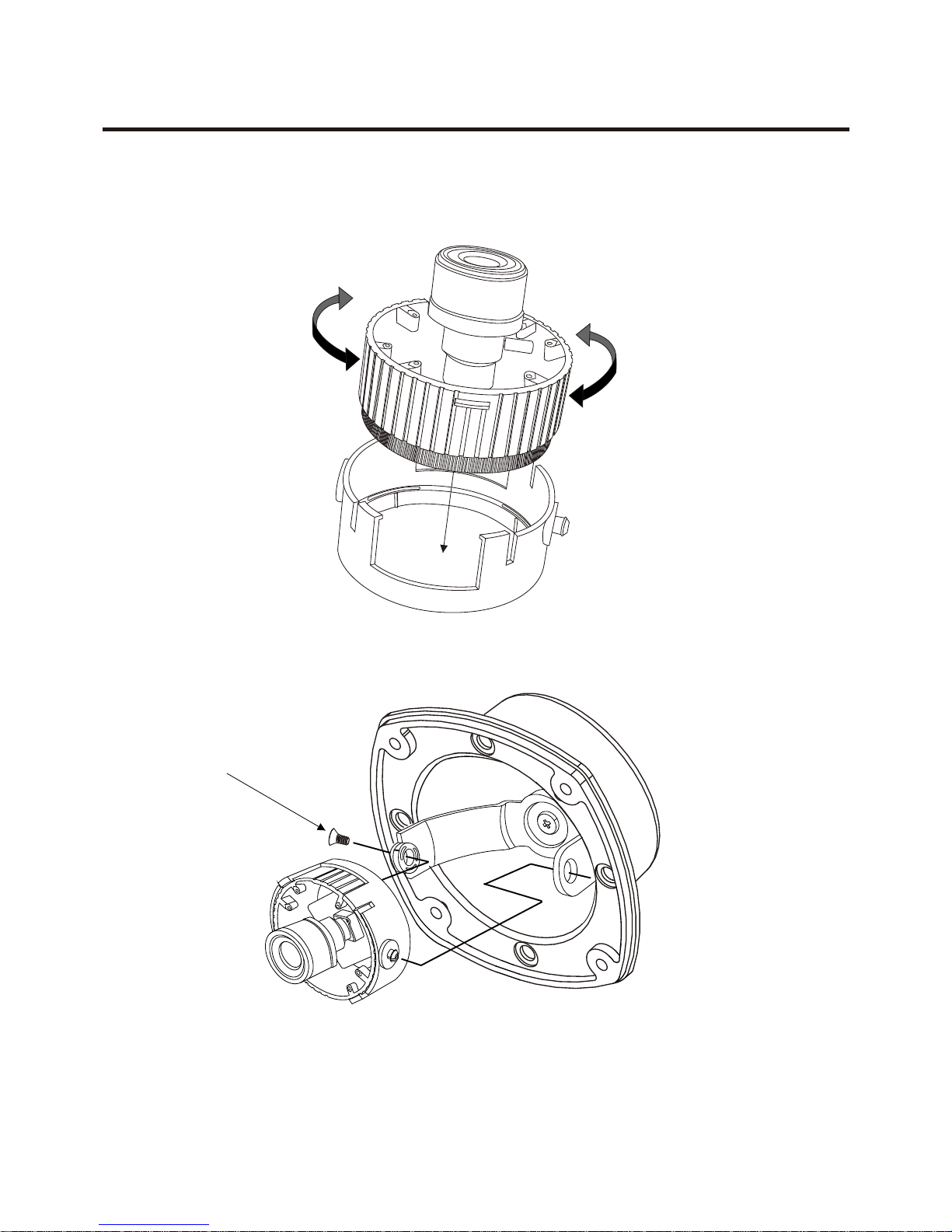
INSTALLING & ADJUSTING CAMERA MODULE (VVRD4V9)
- 5 -
Use the following drawings to install the camera module to the housing.
Screw Taptite(FC)
M3x6

INSTALLING & ADJUSTING CAMERA MODULE (VVRD4V9-LP)
Use the following drawings to install the camera module to the housing.
Screw Taptite(FC)
M3x6
- 6 -
INSTALLING & ADJUSTING CAMERA MODULE (VVRDF4V9)
- 7 -
Use the following drawings to install the camera module to the housing.
Screw Taptite(FC)
M3x6

BASE INSTALLATION (VVRDF4V9)
- 8 -
CAUTION : When installing the camera outdoors, the following instructions
must be followed closely.
2 Adhere the drilling guide label on the proper location.
3. Drill 4holes into the drilling guide label for the screw anchors.
Insert the screw anchors and attach the housing to the screw anchors
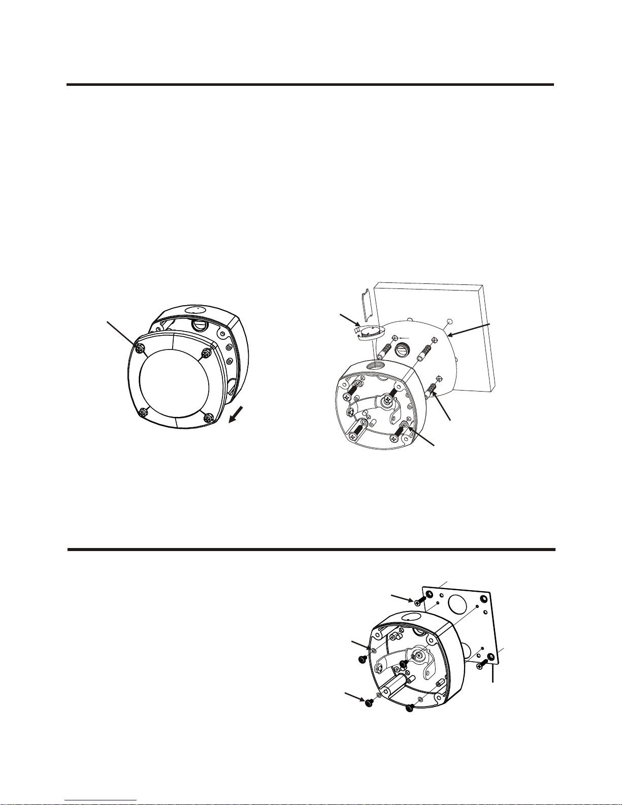
MOUNTING HOUSING TO ELECTRICAL BOX
The housing can also be mounted
on a 4s electrical box.
The housing can also be mounted
on a 2s electrical box.
Plastic
anchors (4x)
Teflon Tape
Torx screws
M6 x 35 (4x)
Wall / Ceiling
4Poin -
t
D in s ti nrill g Po i o
Drilling Guide
Label
50201600A
1. Loosen the four Torx screws on the housing cover. Do NOT remove the screws
from the cover.
Torx Screws
UNC 8-32 x 0.75
Dummy plugs(x2)
Torx Screws
UNC 8-32 x 0.75
Torx screws
M3 x 12 (4x)
- 9 -
CAUTION : When installing the camera outdoors, the following instructions
must be followed closely.
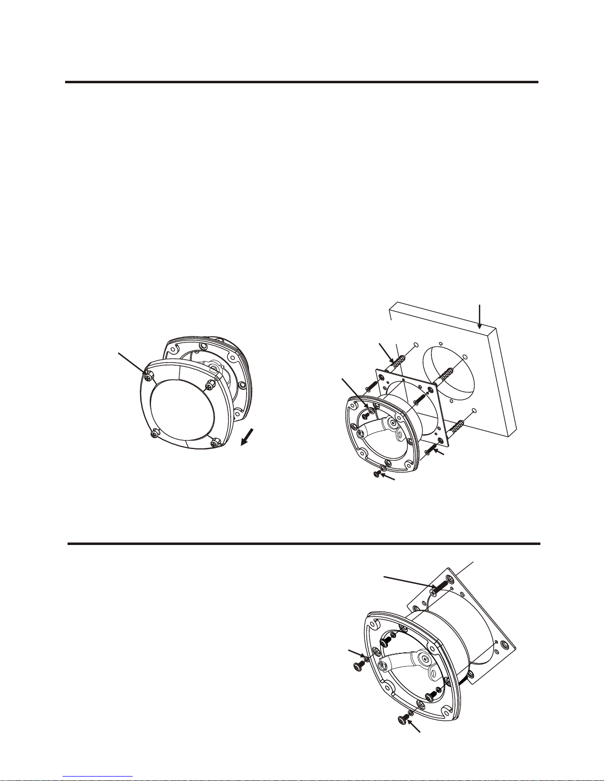
BASE INSTALLATION (VVRD4V9-LP)
1. Loosen the four Torx screws on the housing cover. Do NOT remove the screws
from the cover.
2. Adhere the drilling guide label on the proper location.
3. Drill 4holes into the drilling guide label for the screw anchors.
Insert the screw anchors and attach the housing to the screw anchors.
Torx
screws (4x)
The housing can also be mounted
on a 4s electrical box by
attaching it to the cover
plate of the electrical box.
8-32x0.75
Flat head
screws (2x)
Rubber
washers (4x)
M4x8 pan head
screws (4x) Electrical Box
CoverPlate
MOUNTING HOUSING TO ELECTRICAL BOX
Teflon Tape
WALL/CEIL GIN
Rubber
Washers (4x)
Anchors (4x)
5020 15 98 A
Drilling Guide
label
i -
4Pont
l P
Drling osit
iion
- 10 -
CAUTION : When installing the camera outdoors, the following instructions
must be followed closely.
1. Loosen the four torx screws located midway up the front of the housing. Leave
the screws intact in the front portion.
2. Drill the mounting location, using the bottom of the housing as a template.
BASE INSTALLATION (VVRDF4V9)
3. Use silicone sealant around the rubber grommet to protect it against water intrusion.
4. Before closing the housing, take off the protective nylon and insert the supplied
desiccant bag.
Note: Silicone sealant is not supplied.
The housing can also be mounted
on a 4s electrical box.
MOUNTING HOUSING TO ELECTRICAL BOX
Torx
screws (4x)
M4X8 pan head
screws (2x)
Wall / Ceiling
Rubber
washer
FC1 M4X20 flat head
screws (4x)
M4 plastic
anchors (4x)
M4x8 Pan Head
Screws (4x)
8-32 X 0.75
Flat Head
Screws (2x)
Rubber
Washers (4x)

Use the following drawings to install the camera the heater kit in the housing.
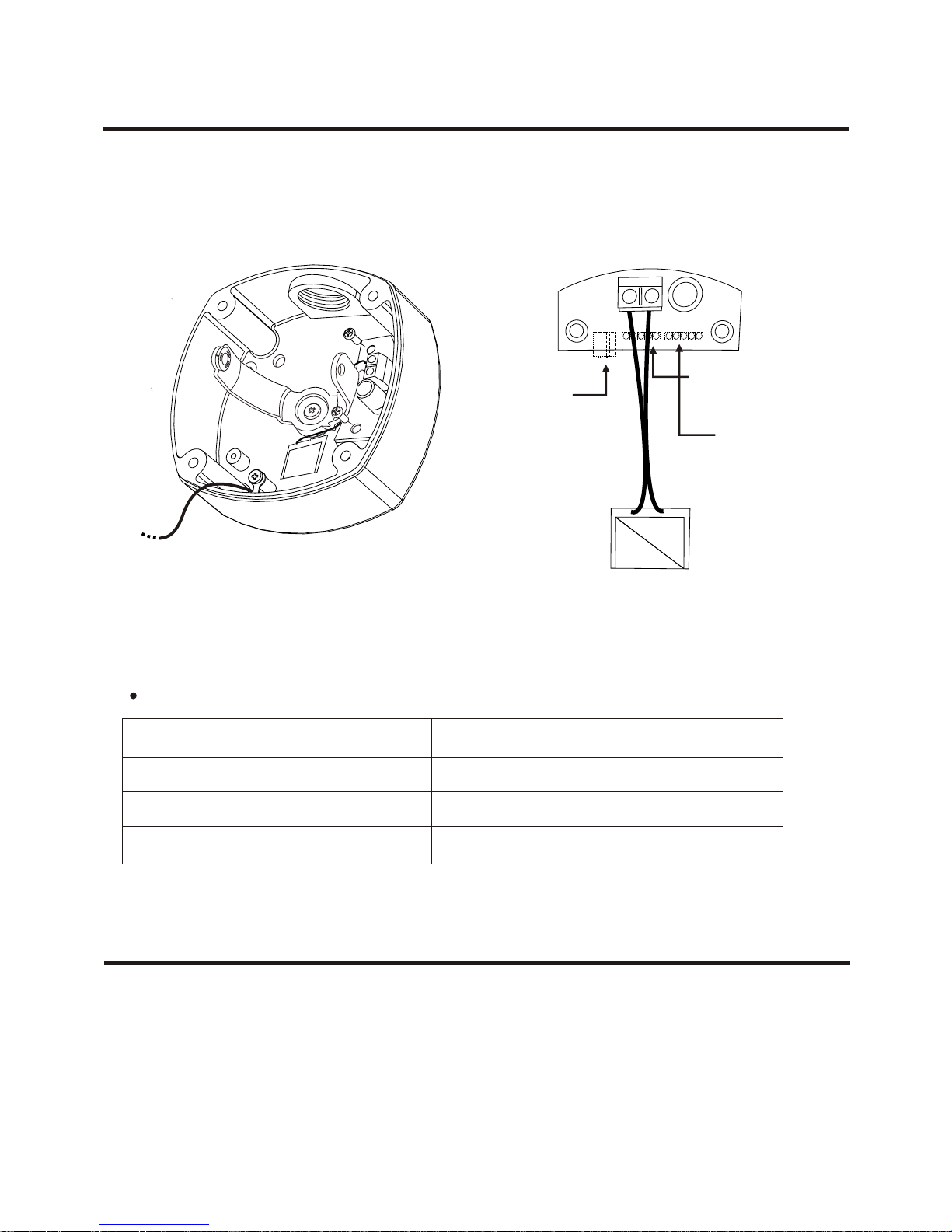
HEATER KIT INSTALLATION (VVRD4V9)
Power Supply 24V AC / 12V DC
Power Consumption 20W
o o
Heater ON at 41 F (5 C)
o o
Heater OFF at 59 F (15 C)
HEATER (IF APPLICABLE)
Camera
Power Cable
(DC 12V)
AC 24V
Power Cable
12VDC TYPE CAMERA CABLE DUAL(24VAC/12VDC) TYPE CAMERA CABLE
HEATERHEATER
- 11 -
Power Supply 24V AC / 12V DC
Power Consumption 20W
o o
Heater ON at 41 F (5 C)
o o
Heater OFF at 59 F (15 C)
HEATER (IF APPLICABLE)
HEATER KIT INSTALLATION (VVRD4V9-LP)
Use the following drawings to install the camera the heater kit in the housing.
POWER
Use Certified/Listed Class 2 power supply transformer only.
Camera
Power Cable
(DC 12V)
AC 24V
Power Cable
HEATER
- 12 -

LENS ADJUSTMENT (OPTIONAL VARIFOCAL LENS)
Field of view: Adjust setting from Telephoto (T)
to wide (W) field of View.
Focus: Adjust lens focus from near
(N) to infinity ( ).
N
TW
Adjust Focus
Adjust Angular Field View
ADJUSTMENTS
Phase adjustment is used in a multi-camera system when power is supplied
from a different source, causing the camera to be out of phase. This affects
auto-switching of the cameras by causing a vertical flip or roll during the switch
interval. The vertical phase adjustment allows the camera's line lock sync to be
adjusted from 0 to 360 degrees with reference to the zero line crossing of the
AC power source.
A. Ensure that all cameras are powered from the same electrical
source and wired in a similar fashion.
B. Adjust the phase control on the camera until there in no
vertical flip or roll on the monitor when using an auto switcher.
Vertical Phase
Vertical Phase:
Colour
- 13 -

DC AUTO IRIS ADJUSTMENT
IRIS LEVEL
DC AUTO IRIS LENS
Image Size 1/3" CCD
Focal Length
Aperture Ratio
Angular
Field of View
SPEC
DIAGONAL
o
4mm : 92.4
o
9mm : 39.2
4.0-9.0mm 5%( 2.6-6.0.mm 5%)
1 : 1.6~2.4 5%
Black Control (-)
White Control (+)
Red Drive (+)
Green Drive (-)
LENS
- 14 -
Description

SHTR Switch (Aes/Mes) - This switch allows the user to choose between auto
exposure and manual exposure. Position the switch toward the front of the
camera for auto exposure, whereby the exposure is performed by the electronic
iris and AGC control. Position the switch toward the back of the camera for
manual exposure, whereby the shutter speed can be set by the shutter adjust.
*Manual Exposure (SHTR = MES)
Flickerless Switch (off/on) - (SHTR=Aes) This function is used for
removing flicker, when camera signal format does not coincide with power source
frequency being used.
BLC Switch (on/off) - (SHTR=Aes) This on/off switch controls
backlight compensation. When set to ON, the camera will automatically try to
maintain proper exposure in the specific area even if the lighting level changes.
E/I (on/off) - (SHTR=Aes)
When set to the ON position, the electronic iris switch automatically varies the
camera's shutter to mimic auto-iris control, allowing fixed or manual iris lenses to
be used in a wider range. When this switch is set to ON, turn the F/F switch OFF.
1.
2.
3.
4.
FUNCTION SWITCH
Switch Position
1 2 3 4
MES
MES
MES
MES
MES
MES
MES
MES
up
down
Shutter Speed
Switch(SW1)
1/50
1/120
1/250
1/500
1/1000
1/2000
1/4000
1/10000
Sw 1 2 3 4
down
down
down
down
down
down
down
down
down
up
up
up
up
up
up
up
up
up
NC BW MAN HI OFF OFF ON MES
8 7 6 5 4 3 2 1
ON
DIP
Colour
Day/Night
down
down
up
up
Nor
AGC
ON
EI
ON
BLC
OFF
FF
AES
SHTR
Auto
- 15 -
This manual suits for next models
1
Other NORBAIN Security Camera manuals

Popular Security Camera manuals by other brands

ASA Electronics
ASA Electronics Voyager VBCYL15 Specification sheet

Kodak
Kodak IP101WG user manual

Moog Videolarm
Moog Videolarm SSDP75CN Installation and operation instructions

Bosch
Bosch AutoDome 600 Series installation manual

LEGRAND
LEGRAND 430 521 instruction manual

First Alert
First Alert CM480 user manual


