manuals.online logo
Brands
  1. Home
  2. •
  3. Brands
  4. •
  5. Norcold
  6. •
  7. Refrigerator
  8. •
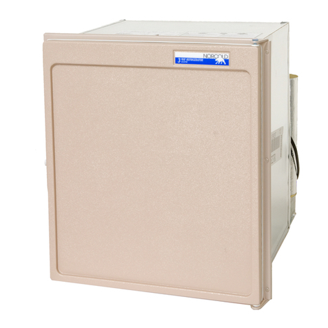
  9. Norcold 982F User manual

Norcold 982F User manual

1
UPPER & LOWER SIDE
VENT INSTALLATION
FOR NORCOLD MODELS 900/9100/N600/N800
Read these important instructions carefully. Become thoroughly acquainted with the
content before installing vents and refrigerator.
IMPORTANT NOTE: Norcold’s
Venting and Installation
instructions must be followed.
These
Upper and Lower Side Vent Installation
instructionsareinadditiontoNorcold’s
Ventilation and Installation
instructionsthataccompanyeachrefrigerator. Followthe
Venting
and Installation
instructions wheninstalling therefrigerator. Installationmust conformwithlocal
codes,or in the absence oflocalcodes, with these standards:
In the United States:
- NationalFuel Gas Code, ANSI Z223.1.
- ManufacturedHome construction andSafety Standard, Title 24CFR,Part 32-80.
- StandardforRecreational Vehicles, ANSIA119.2latest edition.
In Canada:
- Current CGA B149.1 and CGA B149.2 installation code for Propane Appliances and Equip-
ment.
- CurrentCSA Z240.4.2 InstallationRequirementfor Propane AppliancesandEquipment in
RecreationalVehicles.
- CurrentCSA Z240.6.2/C22.2 No. 148 ElectricalRequirementfor Recreational Vehicles.
Wheninstalled, the refrigeratormustbe electrically groundedinaccord with localorstate codes,
theNational Electrical code, andANSI/NFPA70. InCanada, grounding isinaccord with the
Canadian Electrical Code C22.2.
LPGas supply pipingandfittings must complywithlocal, state, andnationalcodes governing type
andsize. These components should also complywiththe current NFPA 501C section 2.41,1990
andwith the currentCAN 1-6.10 Standard.
Important!
During storage of the refrigerator in the RV or the trailer, always disconnect the power
source.
Part No. 618698C (7-98)
2
Upper and Lower Side Vent Installation
Theseinstructions provide analternative method forinstallingNorcold 6 and8 cubic foot
refrigerators(see Table1). This method allowsfor using twolowervents. The second lowervent
servesas the upperexhaust vent, replacingtheroof vent. Use onlythose vents specifiedinthe
refrigeratorinstallation guide forside wall installation.
RefrigeratorModels
8 Cubic Foot Models
982F, 9182F, 982-FIM, N820F, N821F
N841F,N841-FIM
A=62”minimum
1. Installthe lowerintakevent flushwiththe refrigeratormountingsurface (seeFigure1, #1). this
locationprovides thenecessaryventilation fromoutsidethe vehicle.
2. Installthe upperexhaustvent (seeFigure 1,#2)directly abovethelower ventatthe A
dimension,(seeFigure 1 and Table 1) for the model beinginstalled. Positionthis vent directly
behindthe coolingunitcondenser toallowheat andexhaustfrom thecoolingunit toventto the
outside.
6 Cubic Foot Models
962F, 9162F, 962-FIM, N620F, N621F
N641F,N641-FIM
A=55”minimum
Side View Rear View
Figure 1
Table 1
3
Ventilation Fan Installation
To ensureefficientperformance,acontinuousair flow is required across therefrigerator’scooling
system. Athermostat controlled fanmustattach to therefrigerator’scoolingsystembefore
placingthe refrigerator in theenclosure. Thisfan assists air flowacrossthe cooling system. The
thermostatturns onthefan whenevertherefrigerator’s cabinettemperaturereaches 95°
Fahrenheit. Evenwith the fan, theairflow from the sideintakevent across the refrigerator’s
coolingsystem to the exhaustventmust be unobstructed.
Figure2showstheback of the refrigerator and the location of he 1st and 2nd absorber coils.
AlsoinFigure 2 are items installation andtheirapproximatelocations.
Figure 2
MountingPlates
4
Fan Installation
1. Positionmountingbracket A(See Tools and PartsList,#I)around the top ofthetwoabsorber
coils.Make sure the wider flangeofmounting bracket Ais to the bottom. Theflangesof
mountingbracketAface away fromtherefrigerator cabinet. See Figure 3.
2. Positionmountingbracket B (See Tools andPartsList,#J) around the front of the1stand2nd
absorber coils. See Figure 2. This bracket has a wiring label on it. Push mounting bracket B
andmounting bracketAtogether.
NOTE: Mountthe flange of bracket Boverthebottom flange ofbracketA. Insert two 1 1/4”
bracketscrews. See Figure 4. DO NOT fully tighten.
Figure 3
Figure 4
5
3. Slidemountingbrackets along the absorber coils. Leave a3”clearancebetween the right
edgeofthe brackets and the cooling unit’sreturntube. SeeFigure 5.
4. Tighten11/4”mountingbracket screws securing bracket to cooling system. See Figure 5.
5. Place 12 VDC fan on top of the mounting bracketB (label side up) and fan wires exiting to the
leftside (when viewedfromthe back).
Inserttwo 2” fanmountingscrews and tightentosecure fan tomountingbracket. See Figure 4.
Do not over tighten, causingplasticfanhousingto crack. Ensure fan wires do not contact
thesharpedges of the bracket or arepinchedinany way.
NOTE: Wheninstalling fan, leave remaining wiresinplastic bag to prevent themfrompinching.
Figure 5
6
Thermostat Installation
1. Viewingtherefrigeratorfrom the rear, mount thethermostatto the rightcondenserfin.
Removewires from theplasticbag. Untangle anywiresthat are connectedtothe thermostat
andthe fan. Align theholesof the thermostatwiththe left slotinthe condenser fin.SeeFigures
2 and 6.
IMPORTANT: Thethermostatis fragile, handle it withcare. Donot hit the plastic thermostat
withthe screwdriver orallow the screwdrivertoslip off thescrew and contacttheplastic.
NOTE: The41”red wire goes to the leftterminal. The60”red wire (and attached fuse holder)
goesto the rightterminal.
2. Inserta #8 x3/8” screw throughthebottom hole ofthe thermostat andintothe lowestpointof
theleft condenser finslot. Tightenthescrew 1 or2turns to holdthethermostat in place. See
Figure6.
3. Inserta #8 x3/8” screw throughthetop hole ofthe thermostat andintothe condenserfinslot.
See Figure 6.
4. Tightenthescrews to securethe thermostat tothecondenser fin.
IMPORTANT: Do not overtighten the screws.
Figure 6
7
Wire Connections
Wiring:
Splice to Circuit Board (CB) (For 900, 9100, N600, N800 Models):
- Routethe6” red spliced wire and attached 60” red fused wirebetweenthefront and back
absorber coils (Figure 2).
- Connect the female end of the 6” red spliced wire to the +12 V CB (circuit board) terminal
(Figure7).
- Routethe6” black spliced wire and attached 24” black wire betweenthefrontand back
absorber coils (Figure 2).
- Connect the female end of the 6” black spliced wire to the 12 VCOM CB ground terminal
(Figure7).
- Secureall wires so they donotcontact hot surfaces or sharpedgeson the condenser fins or
absorber coils. Use cable ties and adhesive mounting plates (figure 2) as described below.
- Use a cable tie to secure the 41” red wire, the 6” red wire, and the 24” black wire to the
pressurerelief valve(Figure5).
8
900 / 9100 / N600 / N800 Series
Side Wall Venting Components Required
For Assembly Kit Part Number 619020
QTY PART NUMBER DESCRIPTION
1.......618698b............. InstallationInstructions
2. .....61633330............ #8x 3/8”Thermostat MountingScrews
2......61581122............ #6x 11/4”Bracket Mounting Screws
2........618951.............. #8 x2” FanMountingScrews
1........618978.............. 6”RedQuickConnectSpliceWire #18 Gauge 4/64” Thermoplastic
Insulation
1........619017.............. 6”Black Quick connect Splice Wire #18 Gauge 4/64” Thermoplastic
Insulation
2........618950.............. Tie RapMountingPlate Adhesive Backed
1........619018.............. Fan Wiring Diagram Label
1........618699.............. 60” Red #18 GaugeWire w/4/64” PVC Insulation,w/Quick Connect
Terminals, w/DC Fuse Holder
1........618700.............. 24”Black#18 Gauge Wire w/4/64”PVCInsulation, w/Quick Connect
Terminals
1........618701.............. 41”Red #18 Gauge Wirew/4/64”PVC Insulation, w/ QuickConnect
Terminals
1........618856.............. 12 VDC Fan (Brushless .30 Amps)
1........618093.............. 12 VDC Thermostat (130 On / 115 Off)
1........619016.............. Fan Support Mounting Bracket(B)
1........618857.............. Fan Support Mounting Bracket(A)
4......61417922............ Cable Ties
1........619023.............. Package Label
1........619286.............. Thermostat Warning Note
5. Pullthe wires straight downfromthe thermostat and placeamounting plate about 12”down
fromthe condenser sothewires do nottouchthe condenser orthevertical tubing. Secure the
wiresto the mounting platewitha tie wrap. Place themountingplate under the sumpandto
theleftof the fan (Figure 2). Fold theexcesswireas shown. Tie the folded wires to the
mountingplate under thesumpwith a cabletieto prevent thewiresfrom moving byairflow.
Thisalso prevents excess wirefromgetting caught between thesideof the refrigerator and
theenclosure. Makesure the wires arepulledin tight between thetiewrap locations and that
thetie wraps are firmlysecured.
Therefrigerator is nowready for installation.
IMPORTANT: Install the refrigerator according to Norcold’s installation instructions.
9

This manual suits for next models

13

Other Norcold Refrigerator manuals

Norcold 682 User manual

Norcold

Norcold 682 User manual

Norcold 3163 Series Installation and maintenance instructions

Norcold

Norcold 3163 Series Installation and maintenance instructions

Norcold N620 User manual

Norcold

Norcold N620 User manual

Norcold 121 AC series User manual

Norcold

Norcold 121 AC series User manual

Norcold Polar 7 Series User manual

Norcold

Norcold Polar 7 Series User manual

Norcold N300 User manual

Norcold

Norcold N300 User manual

Norcold DC-351D User manual

Norcold

Norcold DC-351D User manual

Norcold N180.3 Series Instruction Manual

Norcold

Norcold N180.3 Series Instruction Manual

Norcold 1210ACIM - User manual

Norcold

Norcold 1210ACIM - User manual

Norcold MRFT460 User manual

Norcold

Norcold MRFT460 User manual

Norcold 2117 User manual

Norcold

Norcold 2117 User manual

Norcold N3104 User manual

Norcold

Norcold N3104 User manual

Norcold 442 User manual

Norcold

Norcold 442 User manual

Norcold Polar 7 Series User manual

Norcold

Norcold Polar 7 Series User manual

Norcold 1210 - User manual

Norcold

Norcold 1210 - User manual

Norcold DE-0751S User manual

Norcold

Norcold DE-0751S User manual

Norcold 2118IM User manual

Norcold

Norcold 2118IM User manual

Norcold N61X Series User manual

Norcold

Norcold N61X Series User manual

Norcold 322X Installation instructions

Norcold

Norcold 322X Installation instructions

Norcold N41X User manual

Norcold

Norcold N41X User manual

Norcold DE / EV 0061 User manual

Norcold

Norcold DE / EV 0061 User manual

Norcold N410 User manual

Norcold

Norcold N410 User manual

Norcold N1095 Series User manual

Norcold

Norcold N1095 Series User manual

Norcold 121X series User manual

Norcold

Norcold 121X series User manual

Popular Refrigerator manuals by other brands

Electrolux ERO 3298 operating instructions

Electrolux

Electrolux ERO 3298 operating instructions

Hallman HRBIAF18PR user manual

Hallman

Hallman HRBIAF18PR user manual

Beko DNE 46000 manual

Beko

Beko DNE 46000 manual

Svan SVF1853NF user manual

Svan

Svan SVF1853NF user manual

JUNO JKI 4054 operating instructions

JUNO

JUNO JKI 4054 operating instructions

Tricity Bendix TB 117 FF Operating & installation instructions

Tricity Bendix

Tricity Bendix TB 117 FF Operating & installation instructions

Beko RCSA225K21W manual

Beko

Beko RCSA225K21W manual

Kogan KAM545FRSFA user guide

Kogan

Kogan KAM545FRSFA user guide

Zanussi ZFK 18/8 Instruction booklet

Zanussi

Zanussi ZFK 18/8 Instruction booklet

Whirlpool WRX988SIBM Energy guide

Whirlpool

Whirlpool WRX988SIBM Energy guide

Kenmore 7830 - 22.6 cu. Ft. Trio Bottom Freezer... Use & care guide

Kenmore

Kenmore 7830 - 22.6 cu. Ft. Trio Bottom Freezer... Use & care guide

Beko CSA22022 instructions

Beko

Beko CSA22022 instructions

Fisher & Paykel RF610ADW5 manual

Fisher & Paykel

Fisher & Paykel RF610ADW5 manual

Guzzanti GZ 09B instruction manual

Guzzanti

Guzzanti GZ 09B instruction manual

SKIPIO Salad Series Service manual

SKIPIO

SKIPIO Salad Series Service manual

Kenmore 111.7269 Use & care guide

Kenmore

Kenmore 111.7269 Use & care guide

Sub-Zero BI-30U installation guide

Sub-Zero

Sub-Zero BI-30U installation guide

IKEA ISC23CDEXB00 User instructions

IKEA

IKEA ISC23CDEXB00 User instructions

manuals.online logo
manuals.online logoBrands
  • About & Mission
  • Contact us
  • Privacy Policy
  • Terms and Conditions

Copyright 2025 Manuals.Online. All Rights Reserved.