Norcros Triton Shower tower User manual

INSTALLERS PLEASE NOTE THESE INSTRUCTIONS ARE TO BE LEFT WITH THE USER
2180363B Feb 2003
Shower Tower
manual mixer
Installation and
Operating
Instructions

Shower tower
CONTENTS Page
Introduction 1
Safety warnings 1
Main components 2
Site requirements 3
Typical installations 4 - 5
Preparing the mixer valve 6
Siting of shower 6
Installation 6 - 8
Using the mixer control lever 9
Using the diverter valves 9
Adjusting the sprayhead 10
Maintenance 10
Spare parts 11
Fault finding 12 - 13
Guarantee, service policy, etc. rear cover
UKAS
QUALITY
MANAGEMENT
003

Shower tower
1
INTRODUCTION
This book contains all the necessary fitting and
operating instructions for your Triton Shower
Tower manual mixer shower. Please read them
carefully.
Read through the whole of this book before
beginning your installation.
The shower installation must be carried out by a
suitably competent person and in sequence of
this instruction book.
Care taken during the installation will ensure a
long and trouble free life from your shower.
This shower tower is designed to operate on
the higher pressure systems found in the UK up
to a maximum of 6 bar running pressure.
The shower MUST NOT be subjected to water
temperatures above 80°C.
This mixer shower is suitable for fully
modulating type combination boilers and multi-
point hot water heaters. It is also suitable for
thermal storage, unvented systems and
pumped gravity systems.
Important: Before installing with a gas
instantaneous water heater, ensure it is
capable of delivering hot water at a
minimum switch-on flow rate of 3 litres per
minute. At flow rates between 3 and 8 litres
per minute, the appliance must be capable of
raising the water temperature to a minimum
of 52°C. Water temperature at the inlet to
the mixer must remain relatively constant
when flowrate adjustments are made (refer to
the water heater operating manual to confirm
compatibility with this shower tower).
This shower tower is supplied with an integral
single check valve and integral large area filter
in each inlet elbow. Inlet connections are by
braid hoses having 1/2” BSP unions.
SAFETY WARNINGS
a Layout and sizing of pipework must be such
that when other services are used, pressures
at the shower control inlets DO NOT fall
below the recommended minimum.
b DO NOT choose a position where the
shower could become frozen.
c DO NOT connect this mixer shower to any
form of tap or fitting not recommended by
the manufacturer.
d The sprayhead must be regularly cleaned to
remove scale and debris.
e Conveniently situated isolating valves in
each inlet supply must be fitted as an
independent method of isolating the
shower should maintenance or servicing be
necessary.
f If it is intended to operate the shower in
areas of hard water (above 200 ppm
temporary hardness), a scale inhibitor may
have to be fitted. For advice on the Triton
scale inhibitor, please contact Customer
Service.
g Do not operate the shower outside the
guidelines as laid out in ‘site requirements’.
Replacement parts can be ordered from Triton
Customer Service. See ‘spare parts’ for details
and part numbers.
Due to continuous improvement and updating,
specification may be altered without prior notice.
To ensure the product suitability for
commercial and multiple installations, please
contact Triton’s specification advisory service
prior to installation.
Telephone: (024) 7632 5491
Facsimile: (024) 7632 4564
Shower tower
2
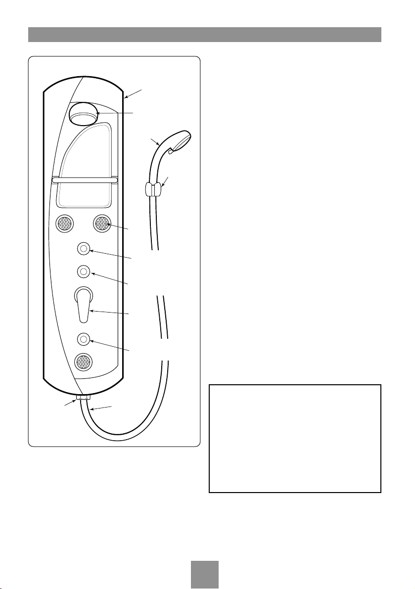
MAIN COMPONENTS
Thank you for purchasing our high quality
product. Check components and quantity
before installation. In the unlikely event of
anything being amiss, please contact Triton
Customer Service.
Pack contents
Showertower body - 1 off
Fixed head - 1 off
Handset and hose - 1 off
Manual mixer valve control lever - 1 off
Diverter valves - 3 off
Body jets - 3 off
Elbows with filters and check valves - 2 off
Hanging brackets - 2 off
Screws and wall plugs - 4 off
Guarantee.
Important notes before you start
This product has passed a factory control test
before reaching you. Do not attempt to
dismantle or modify it.
●Ensure there are no hidden service pipes and
cables where you intend to drill.
●Ensure the hot and cold supply pipes are
flushed out before final connection to the unit.
●The working pressure of this product is 0.5
bar – 6 bar. (7 bar static)
●Please be aware of your safety while drilling
and installing.
Showertower
body
Fixed head
Body
jets
Diverter valve
(fixed head)
Diverter valve
(body jets)
Diverter valve
(handset)
Mixer
control
lever
Handset
Handset
hose
Handset
bracket
Outlet
connector
Fig.2
WARNING!
The shower tower mixer valve is NOT
thermostatic and will NOT prevent
water flowing from the spray outlets
should there be a loss of one supply to
the inlets.
This product is NOT suitable for low
pressure gravity fed supplies unless a
suitable pump is also installed.

Shower tower
3
SITE REQUIREMENTS
The installation must be in accordance with
Water Regulations and Byelaws.
Minimum running water pressure: 0.5 bar
Maximum running water pressure: 6 bar
Maximum static water pressure: 7 bar
For otimum performance an operating
pressure of 3 bar running is required.
Both hot and cold supplies should be at
nominally equal pressures with a minimum flow
rate of 8 litres per minute to both inlets.
While the shower tower is operational (open
outlet), inlet pressures must not be capable of
exceeding 6 bar. For effective operation of the
internal seals, the maximum static pressure
must not be exceeded.
Note: On sites where the running pressure is
above 6 bar, the use of a suitably sized pressure
reducing valve fitted in the cold mains supply
pipework can provide nominally equal pressures
at the showertower.
For a satisfactory performance from the shower
tower both cold and hot inlet supplies must be
from a balanced supply.
Additional isolating valves must be fitted as an
independent means of isolating the water
supplies should maintenance be necessary.
The pipework should be installed such that the
flow is not significantly affected by other taps
and appliances being operated elsewhere on
the premises.
Note: Where thermal store systems and
instantaneous gas water heaters are used, if
excessive draw offs take place the boiler may
not be able to maintain an adequate output
temperature. This could result in the
showertower temperature becoming noticeably
cooler.
DO NOT use jointing compounds on pipework.
Water temperature requirements
Recommended maximum 65°C.
BS6700 recommends the temperature of stored
water should never exceed 65°C.
A stored water temperature of 60°C is
considered sufficient to meet all normal
requirements and will minimise the effects of
scale in hard water areas.
Temperature adjustment range
The mixed water temperature can be adjusted
from cold through to the temperature of hot
water available from the hot water appliance.
Flow rate performance
For all systems, the ability to use showerheads
and body jets simultaneously is dependent on
domestic hot water pressures and flow rates.
Table of contents
Popular Bathroom Fixture manuals by other brands

Kohler
Kohler Mira Sport Max J03G Installation and user guide

Moen
Moen 186117 Series installation guide

Hans Grohe
Hans Grohe Raindance Showerpipe 27235000 Instructions for use/assembly instructions

Signature Hardware
Signature Hardware ROUND SWIVEL BODY SPRAY 948942 Install

fine fixtures
fine fixtures AC3TH installation manual

LIXIL
LIXIL HP50 Series quick start guide


