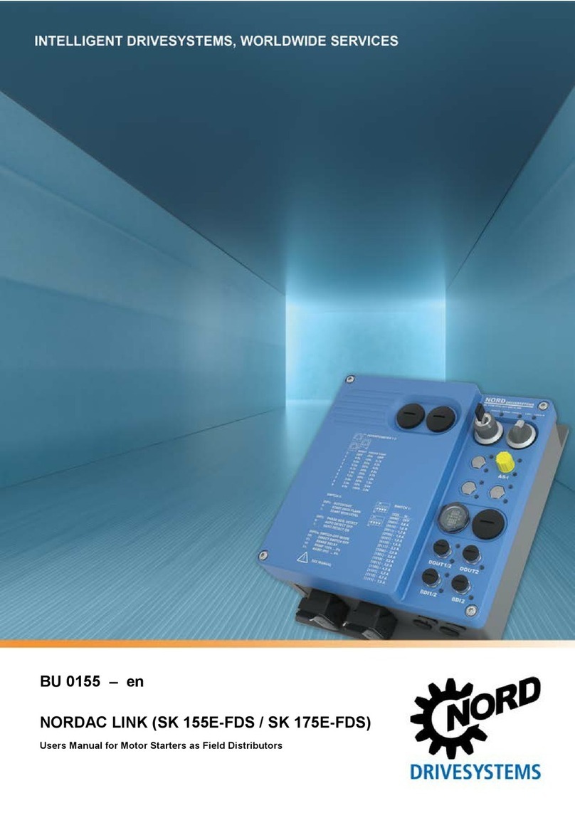
Nord Drivesystems NORDAC LINK SK 155E-FDS Series User manual

BU 0155 – en
NORDAC LINK (SK 155E-FDS / SK 175E-FDS)
Users Manual for Motor Starters as Field Distributors

NORDAC LINK (SK 155E-FDS / SK 175E-FDS) – Users Manual for Motor Starters as Field Distributors
2 BU 0155 en-3520
Documentation
Title:
BU 0155
Order no.:
6071502
Series:
SK 1x5E-FDS
Device series:
SK 155E-FDS, SK 175E-FDS
Device types:
SK 1x5E-FDS-111-340-xxx 0.25 – 3.0 kW, 3~ 380-500 V
SK 1x5E-FDS-301-340-xxx
Version list
Title,
Date
Order number Device
software
version
Remarks
BU 0155,
September
2016
6071502/ 3916
V 1.0 R0
First edition for pilot series devices (field test).
BU 0155,
July 2017
6071502/ 2817
V 1.0 R2
• Names of option slots for control elements changed
to H1, H2 and H3
• Power connection plug and M12 plug connector:
Correction of various pin connections
• Parameter P434, function 21 added
• Parameters P203, P570: Value range changed
• Potentiometers P1 and P2: Setting values changed
• DIP switch S1: Setting values changed
• CE Declaration of Conformity added
• Various other corrections
BU 0155,
April 2018
6071502/ 1618
V 1.0 R2
For instance
• General corrections
• Adaptation of safety information
• Revision of warnings and hazard notes
• Inclusion of UL data
• AS-Interface supplement “AXS” single slave
• Connection accessories added
• Update of EU Declaration of Conformity
BU 0155
,
September
2020
6071502
/ 3520 V 1.2 R0 For instance
• General corrections
• Size 0 added
• Parameter P130 enhanced by combined mode
• Parameter P539 enhanced
• New parameter P780
• Chapters “Motor cables”, “Mains cables” and “Daisy
chain cables” added
Table 1: Version list

Copyright notice
BU 0155 en-3520 3
Copyright notice
As an integral component of the device described here, this document must be provided to all
users in a suitable form.
Any editing or amendment or other utilisation of the document is prohibited.
Publisher
Getriebebau NORD GmbH & Co. KG
Getriebebau-Nord-Straße 1 • 22941 Bargteheide, Germany • http://www.nord.com/
Fon +49 (0) 45 32 / 289-0 • Fax +49 (0) 45 32 / 289-2253
Member of the NORD DRIVESYSTEMS Group

NORDAC LINK (SK 155E-FDS / SK 175E-FDS) – Users Manual for Motor Starters as Field Distributors
4 BU 0155 en-3520

Table of Contents
BU 0155 en-3520 5
Table of Contents
1General.........................................................................................................................................................9
1.1 Overview ..........................................................................................................................................10
1.2 Delivery ............................................................................................................................................11
1.3 Scope of delivery..............................................................................................................................12
1.4 Safety, installation and application information ................................................................................14
1.5 Warning and hazard information ......................................................................................................18
1.5.1 Warning and hazard information on the product.................................................................18
1.5.2 Warning and hazard information in the document ..............................................................19
1.6 Standards and approvals .................................................................................................................20
1.6.1 UL and CSA approval.........................................................................................................20
1.7 Type code / nomenclature................................................................................................................23
1.7.1 Type plate...........................................................................................................................23
1.7.2 Field Distribution System type code ...................................................................................25
1.8 Version with protection class IP65 ...................................................................................................25
2Assembly and installation ........................................................................................................................26
2.1 Installation........................................................................................................................................27
2.2 Option slots and equipment versions ...............................................................................................28
2.2.1 Option slots.........................................................................................................................28
2.2.1.1 Connection level 28
2.2.1.2 Control level 29
2.2.1.3 Maintenance switch level 29
2.2.2 Configuration versions........................................................................................................30
2.2.2.1 Configurable options 30
2.2.2.2 Configuration of option slots of the control level 31
2.2.2.3 Configuration of option slots on the connection level 35
2.2.2.4 Configuration of the option slot for the maintenance switch level 37
2.3 Electrical Connection .......................................................................................................................38
2.3.1 Wiring guidelines ................................................................................................................38
2.3.2 Electrical connection of power unit .....................................................................................40
2.3.2.1 Mains connection 40
2.3.2.2 Motor cable (U, V, W, PE) 41
2.3.2.3 Electromechanical brake 41
2.3.3 Electrical connection of the control unit ..............................................................................42
2.3.3.1 Control connection details 44
3Display, operation and options................................................................................................................46
3.1 Indicator lights..................................................................................................................................47
3.2 Control and parametrisation options ................................................................................................48
3.2.1 Control and parameterisation units, use .............................................................................48
4Commissioning .........................................................................................................................................50
4.1 Factory settings................................................................................................................................50
4.2 Starting up the device ......................................................................................................................51
4.2.1 Connection .........................................................................................................................52
4.2.2 Configuration ......................................................................................................................52
4.2.2.1 Parameterisation 53
4.2.2.2 Potentiometers P1 to P3 54
4.2.2.3 DIP switch (S1, S2) 55
4.2.2.4 Overview of disconnection modes 56
4.3 AS Interface (AS-i) ...........................................................................................................................58
4.3.1 The bus system ..................................................................................................................58
4.3.2 Features and technical data ...............................................................................................59
4.3.3 Bus structure and topology.................................................................................................60
4.3.4 Commissioning...................................................................................................................62
4.3.4.1 Connection 62
4.3.4.2 Displays 62
4.3.4.3 Configuration 63
4.3.4.4 Addressing 65
4.3.5 Certificate ...........................................................................................................................66
4.4 PROFIBUS DP.................................................................................................................................67

NORDAC LINK (SK 155E-FDS / SK 175E-FDS) – Users Manual for Motor Starters as Field Distributors
6 BU 0155 en-3520
4.4.1 The bus system ..................................................................................................................67
4.4.2 Features .............................................................................................................................67
4.4.3 Commissioning...................................................................................................................68
4.4.3.1 Connection 68
4.4.3.2 Displays 68
4.4.3.3 Configuration 68
4.4.3.4 Addressing 70
5Parameter...................................................................................................................................................71
5.1 Parameter overview .........................................................................................................................73
5.2 Description of parameters ................................................................................................................74
5.2.1 Operating displays..............................................................................................................76
5.2.2 Basic parameters................................................................................................................77
5.2.3 Motor data ..........................................................................................................................79
5.2.4 Speed control .....................................................................................................................80
5.2.5 Control terminals ................................................................................................................81
5.2.6 Additional parameters.........................................................................................................85
5.2.7 Information..........................................................................................................................89
6Operating status messages .....................................................................................................................94
6.1 Display of messages........................................................................................................................94
6.2 Diagnostic LEDs on device ..............................................................................................................95
6.3 Messages.........................................................................................................................................96
6.4 FAQ operational problems ...............................................................................................................99
7Technical data .........................................................................................................................................100
7.1 General motor starter data .............................................................................................................100
7.2 Electrical data ................................................................................................................................101
7.2.1 Electrical data...................................................................................................................101
8Additional information ............................................................................................................................102
8.1 Electromagnetic compatibility (EMC) .............................................................................................102
8.1.1 General Provisions ...........................................................................................................102
8.1.2 EMC evaluation - EN 55011-1 (environmental standard) .................................................103
8.1.3 EMC of device ..................................................................................................................104
8.1.4 EU Declaration of Conformity ...........................................................................................105
8.2 Operation on the FI circuit breaker.................................................................................................106
8.3 Trigger classes (I²t) ........................................................................................................................106
8.4 Switch-on cycle ..............................................................................................................................107
8.5 Connection accessories .................................................................................................................108
8.5.1 Power connections - mating connectors...........................................................................108
8.5.2 M12 Y distributor ..............................................................................................................109
8.5.3 Motor cable.......................................................................................................................109
8.5.4 Low voltage cable.............................................................................................................110
8.5.5 Daisy chain cable .............................................................................................................110
9Maintenance and servicing information................................................................................................111
9.1 Maintenance Instructions ...............................................................................................................111
9.2 Service notes .................................................................................................................................112
9.3 Abbreviations .................................................................................................................................113

List of illustrations
BU 0155 en-3520 7
List of illustrations
Figure 1: SimpleBox, handheld, SK CSX-3H......................................................................................................... 48
Figure 2: ParameterBox, handheld, SK PAR-3H................................................................................................... 48
Figure 3: Explanation of parameter description ..................................................................................................... 74
Figure 4: Trigger class curves ............................................................................................................................. 106
Figure 5: Trigger times for warm operating state (with previous: I = continuous Inenn) ......................................... 107

NORDAC LINK (SK 155E-FDS / SK 175E-FDS) – Users Manual for Motor Starters as Field Distributors
8 BU 0155 en-3520
List of tables
Table 1: Version list ................................................................................................................................................. 2
Table 2: Warning and hazard information on the product...................................................................................... 18
Table 3: Standards and approvals......................................................................................................................... 20
Table 4: Configuration – Comparison of hardware and software adjustments ...................................................... 52
Table 5: Parameters and functions depending on P130........................................................................................ 53
Table 6: FAQ operational problems....................................................................................................................... 99
Table 7: EMC - Limit class in accordance with EN 55011 ................................................................................... 103
Table 8: Overview according to product standard EN 60947-4-2 ....................................................................... 104

1 General
BU 0155 en-3520 9
1 General
The SK 1x5E-FDS series is based on the tried and tested NORD platform. The devices are
characterised by their compact design and optimum operating characteristics, and have uniform
parametrisation.
A two-phase phase section enables both motor start and soft start. The phase section procedure is
chosen so that the resulting alternating torques are kept as low as possible. A comprehensive
spectrum of monitoring functions rounds off the portfolio.
Thanks to the versatile setting options, all three-phase asynchronous motors can be operated.
The motor starter is principally designed for a three-phase mains connection. The power range is from
0.25 kW to 3.0 kW.
The device series can be adapted to individual requirements by means of modular assemblies.
This manual is based on the device software as stated in the version list (see P707). If the motor
starter uses a different software version, this may cause differences. If necessary, the current manual
can be downloaded from the internet (http//www.nord.com/).
Additional descriptions exist for optional functions and bus systems (http//www.nord.com/).
Information
Accessories
The accessories listed in the manual are also subject to changes. Current details of
these are
included in separate data sheets, which you can find under http//www.nord.com/ under the heading
Documentation → Manuals → Electronic drive technology → Find techical information/data sheet.
The data sheets available at the date of publication of this manual are listed by name in the relevant
sections (TI ...).
The device series’ various versions result in differences between the functionalities (e.g. with
integrated AS-Interface or integrated PROFIBUS DP bus interface).
The simplest configuration allows for the setting of all important parameters using up to four
potentiometers and four DIP switches without a PC or control device. LEDs are available for
diagnosing the operating states. The use of a control module is therefore not mandatory.
A typical feature of this frequency inverter series is their installation close to the motor, e.g. on the wall
or on a machine frame.
All electrical connections (power connections and control connections) are made with plug connectors.
This considerably simplifies the installation of the frequency inverter and opening the FI is not
necessary.
In order to obtain access to all parameters, the internal RS232 interface (access via RJ12 connection)
can be used. Access to the parameters is made e.g. via an optional SimpleBox or ParameterBox.
The parameter settings modified by the owner/operator must be saved in the Flash memory of the
device (P550). Otherwise the changed parameter settings would be lost when the device was
switched off.
The device is configured according to the customer’s individual requirements. The device equipment is
therefore realised ex works. Later retrofittings of options or device conversions are not planned.

NORDAC LINK (SK 155E-FDS / SK 175E-FDS) – Users Manual for Motor Starters as Field Distributors
10 BU 0155 en-3520
Information
The device must not be opened.
The device must not be opened at any time during its service life and does not need to be. All
mounting, installation and commissioning works are only done on the closed device.
• Assembly is done via freely accessible mounting holes.
• Electrical connection is exclusively established via plug connectors.
• Operational settings are made via parameter adjustments or via DIP switches and potentiometers.
The access to these elements or for the connection of a parameterisation tool is via blind plugs.
These blind plugs may only be removed for works in connection with commissioning and must be
properly replaced afterwards.
• Diagnostic LEDs for displaying switching and operating states are externally visible.
1.1 Overview
This manual describes the total number of possible functions and configurations. Depending on the
device type, the configuration and functions are limited. Devices of type SK 175E-FDS have the
maximum configuration for the integrated additional characteristics.
Basic characteristics
• Close-to-motor mounting as wall mounting
• 5 digital inputsa), b)
• 2 digital outputs b)
• Separate temperature sensor input (TF+/TF-) b)
• Motor overload protection (I2t triggering characteristic according to EN 60947) No motor
protection switch required but only one backup fuse!
• Mains and motor failure monitoring
• Magnetisation monitoring (minimum current monitoring)
• Automatic phase sequence detection
• Soft start
• Permissible ambient temperature -25°C to 50°C (pay attention to technical data)
• Integrated EMC mains filter for Class A limit values
• 2 x DIP switch and 3 x potentiometer for configuration
• LEDs for diagnosis (including signal statuses DIs/DOs)
• RS232-/RS485 interface via RJ12 plug connector, alternatively USB (only RS232)
• 24 V DC control voltage
– Must be provided via a plug connector, or
– can be provided by the device (only with option -HVS).
It is also possible to connect an external 24 V DC voltage supply via optional plug connectors in
order to supply a high-power peripheral (e.g. actuators).
• Integrated PLC (BU 0550)
a)
If necessary, individual inputs may be defined at the factory by
using certain optional modules.
b) Connection is only possible via optional plug connectors.
Additional characteristics
The devices are available in the -AS-i, -AUX, -AXS or -ASS versions with integrated AS-Interface
or -PBR with integrated PROFIBUS DP.
The differences between the individual versions (SK 155E-FDS / SK 175E-FDS) are summarised in
the following table and described in this manual.

1 General
BU 0155 en-3520 11
Characteristic 155E-
Axx a)
155E-
PBR
175E-
Axx a)
175E-
PBR
Reversing function
x
x
AS-Interface (4I/4O)
AS-i
AS-i
PROFIBUS DP (4I/4O)
PBR
PBR
a) AS-i, -AUX, -AXS, -ASS
Optional features
The FI can be individually adapted to the drive task. For this, a comprehensive selection of interfaces,
plug connections and control elements are available, which can be used during the manufacture of the
FI according to the customer's requirements.
Depending on the configuration, the meaning of the individual LEDs, function or assignment of
individual plug connectors or the function of control elements (e.g. switches) may differ. The possible
combinations will be illustrated and explained in the course of this manual. The individual configuration
of the FI can be identified using the type plate and can be compared with the details in the manual.
1.2 Delivery
Examine the frequency inverter for transport damage or loose components immediately on delivery /
unpacking.
In case of damage, contact the carrier immediately and arrange for a careful survey.
Important! This also applies if the packaging is undamaged.

NORDAC LINK (SK 155E-FDS / SK 175E-FDS) – Users Manual for Motor Starters as Field Distributors
12 BU 0155 en-3520
1.3 Scope of delivery
NOTICE
Defect in the device
Use of unapproved accessories and options (e.g. options from other device series (SK CSX 0)) may
result in defects of the interconnected components.
• Only use accessories and options which are explicitly intended for use with this device and stated
in this manual.
Standard version: • IP65 version
• Operating instructions as PDF file on CD ROM including NORD CON, (PC
parametrisation software)
Configurable options and accessories:
Designation Example Description
Control and parametrisation options
Parameterisation units for
temporary connection to the
device, handheld
For commissioning, parametrisation and control
of the device
Type SK PAR-3H, SK CSX-3H
(Section 3.2 "Control and parametrisation
options ")
NORDAC ACCESS BT
NORDAC ACCESS BTin combination with the
NORDCON APP is used for the mobile
parameterisation of the device.
BU 0960
Miscellaneous
Internal fuse module
Interface for protecting the individual device in
the event of "Daisy Chain" wiring (looping
through of mains voltage from one FI to the
next).
SK CU4-FUSE (TI 275271122)
SK CU4-FUSE-C
(TI 275271622)

1 General
BU 0155 en-3520 13
Software / Apps (free download)
NORDCON
on MS Windows ®-based
software
For commissioning, parametrisation and control
of the device.
See www.nord.com
NORDCON
NORDCON APP
NORDAC ACCESS BT in combination with the
NORDCON APP is used for the mobile
parameterisation of the device.
BU 0960
ePlan macros
Macros for producing electrical circuit diagrams
In preparation
Device master data
Device master data/device description files for
NORD field bus options
NORD fieldbus files

NORDAC LINK (SK 155E-FDS / SK 175E-FDS) – Users Manual for Motor Starters as Field Distributors
14 BU 0155 en-3520
1.4 Safety, installation and application information
Before working on or with the device, please read the following safety instructions extremely carefully.
Please pay attention to all other information from the device manual.
Non-compliance can result in serious or fatal injuries and damage to the device or its surroundings.
These safety instructions must be kept in a safe place!
1. General
Do not use defective devices or devices with defective or damaged housings or missing covers (e.g.
blind plugs). Otherwise, there is a risk of serious injury or death from electric shock.
Unauthorised removal of covers, improper use, incorrect installation or operation causes a risk of
serious personal injury or material damage.
During operation, depending on their protection class, devices may have live bare components as well
as hot surfaces.
The device operates with a dangerous voltage. Dangerous voltage may be present at the supply lines,
contact strips and PCBs of all connecting terminals (e.g. mains input, motor connection), even if the
device is not working or the motor is not rotating (e.g. caused by electronic disabling, jamming of the
drive or a short circuit at the output terminals).
The device is not equipped with a mains switch and is therefore always live when connected to the
power supply. Voltages may therefore be connected to a connected motor at standstill. An optional
mains connection outlet is also at mains voltage.
Even if the drive unit has been disconnected from the mains, a connected motor may rotate and
possibly generate a dangerous voltage.
If you come into contact with dangerous voltage such as this, there is a risk of an electric shock, which
can lead to serious or fatal injuries.
Power plug connectors must not be pulled out when they are connected to the power supply. Failure
to comply with this may cause arcing, which in addition to the risk of injury, also results in a risk of
damage or destruction of the device.
The fact that the status LED or other indicators are not illuminated does not indicate that the device
has been disconnected from the mains and is without voltage.
Metal components and the housing of power plug connectors may heat up to temperatures of more
than 70°C.
Touching these parts can result in local burns to the body parts concerned (cooling times and
clearance from neighbouring components must be complied with).
All work on the device, e.g. transportation, installation, commissioning and maintenance work must be
carried out by qualified experts (observe IEC 364 or CENELEC HD 384 or DIN VDE 0100 and
IEC 664 or DIN VDE 0110 and national accident prevention regulations). In particular, the general and
regional installation and safety regulations for work on high voltage systems (e.g. VDE) must be
complied with as must the regulations concerning correct use of tools and the use of personal
protection equipment.
During all work on the device, take care that no foreign bodies, loose parts, moisture or dust enter or
remain in the device (risk of short circuit, fire and corrosion).
Further information can be found in this documentation.
2. Qualified experts
For the purposes of these basic safety instructions, qualified personnel are persons who are familiar
with the assembly, installation, commissioning and operation of this product and who have the
relevant qualifications for their work.

1 General
BU 0155 en-3520 15
Furthermore, the device and the associated accessories may only be installed and started up by
qualified electricians. An electrician is a person who, because of their technical training and
experience, has sufficient knowledge with regard to
• switching on, switching off, isolating, earthing and marking power circuits and devices,
• proper maintenance and use of protective devices in accordance with defined safety standards.
3. Correct purpose of use – general
The Motor starters are devices for industrial and commercial plants for operating three-phase
asynchronous motors with squirrel-cage rotors.
The devices are components intended for installation in electrical systems or machines.
Technical data and information for connection conditions can be found on the rating plate and in the
documentation, and must be complied with.
The devices may only be used for safety functions which are described and explicitly approved.
CE-labelled devices fulfil the requirements of the Low Voltage Directive 2014/35/EU. The stated
harmonized standards for the devices are used in the declaration of conformity.
a. Supplement: Correct purpose of use within the European Union
When installed in machines, the devices must not be commissioned (i.e. commencement of
proper use) until it has been ensured that the machine fulfils the provisions of EC Directive
2006/42/EC (Machinery Directive); EN 60204-1 must also be complied with.
Commissioning (i.e. start-up of proper use) is only permitted if the EMC directive (2014/30/EU)
has been complied with.
b. Supplement: Correct purpose of use outside the European Union
The local conditions of the operator for the installation and commissioning of the device must be
complied with at the usage location (see also "a) Supplement: Correct purpose of use within the
European Union").
4. Phases of life
Transport, storage
The information in the manual regarding transport, storage and correct handling must be complied
with.
The permissible mechanical and climatic ambient conditions (see technical data in the manual for the
device) must be complied with.
If necessary, suitable, adequately dimensioned means of transport (e.g. lifting gear, rope guides) must
be used.
Installation and assembly
The installation and cooling of the device must be implemented according to the regulations in the
corresponding documentation. The permissible mechanical and climatic ambient conditions (see
technical data in the manual for the device) must be complied with.
The device must be protected against impermissible loads. In particular, components must not be
deformed and/or insulation distances must not be changed. Touching of electronic components and
contacts must be avoided.
The device and its optional modules contain electrostatically sensitive components, which can be
easily damaged by incorrect handling. Electrical components must not be mechanically damaged or
destroyed.
Electrical connection
Ensure that the device and the motor are specified for the correct supply voltage.

NORDAC LINK (SK 155E-FDS / SK 175E-FDS) – Users Manual for Motor Starters as Field Distributors
16 BU 0155 en-3520
Installation, maintenance and repair work must not be carried out unless the device has been
disconnected from the voltage and at least 5 minutes have elapsed since the mains was switched off!
(Due to charged capacitors, the equipment may continue to carry hazardous voltages for up to 5
minutes after being switched off at the mains). Before starting work it is essential to check by
measurement that all contacts of the power plug connections or the connection are voltage-free.
The electrical installation must be implemented according to the applicable regulations (e.g. cable
cross-section, fuses, earth lead connections). Further instructions can be found in the documentation
or manual for the device.
Information regarding EMC-compliant installation such as shielding, earthing, location of filters and
routing of cables can be found in the documentation for the devices and in the technical information
manual TI 80-0011. This information must always be observed even with inverters with a CE label.
Compliance with the limit values specified in the EMC regulations is the responsibility of the
manufacturer of the system or machine.
In case of a fault, inadequate earthing may result in electric shock, possibly with fatal consequences.
The device may only be operated with effective earth connections which comply with local regulations
for large leakage currents (> 3.5 mA). Detailed information regarding connections and operating
conditions can be obtained from the technical Information manual TI 80-0019.
Connection of the supply voltage may directly or indirectly set the inverter into operation. Contact with
electrically live components will result in electric shock, possibly with fatal consequences.
All poles of cable connections (e.g. power supply) must always be disconnected.
Set-up, troubleshooting and commissioning
When working on live devices, the applicable national accident prevention regulations must be
complied with (e.g. BGV A3, formerly VBG 4).
The voltage supply of the device may directly or indirectly put it into operation, or touching electrically
conducting components may then cause an electric shock with possible fatal consequences.
The parametrisation and configuration of the devices must be selected so that no hazards can occur.
With certain setting conditions, the device or the motor which is connected to it may start automatically
when the mains are switched on. The machinery which it drives (press / chain hoist / roller / fan etc.)
may then make an unexpected movement. This may cause various injuries, including to third parties.
Before switching on the mains, secure the danger area by warning and removing all persons from the
danger area.
Operation
Where necessary, systems in which the devices are installed must be equipped with additional
monitoring and protective equipment according to the applicable safety requirements (e.g. legislation
concerning technical equipment, accident prevention regulations, etc.).
All covers must be kept closed during operation.
With certain setting conditions, the device or the motor which is connected to it may start automatically
when the mains are switched on. The machinery which it drives (press / chain hoist / roller / fan etc.)
may then make an unexpected movement. This may cause various injuries, including to third parties.
Before switching on the mains, secure the danger area by warning and removing all persons from the
danger area.
Maintenance, repair and decommissioning
Installation, maintenance and repair work must not be carried out unless the device has been
disconnected from the voltage and at least 5 minutes have elapsed since the mains was switched off!
(Due to charged capacitors, the equipment may continue to carry hazardous voltages for up to
5 minutes after being switched off at the mains). Before starting work it is essential to check by
measurement that all contacts of the power plug connections or the connection are voltage-free.

1 General
BU 0155 en-3520 17
For further information, please refer to the manual for the device.
Disposal
The product and its parts and accessories must not be disposed of as domestic waste. At the end of
its life, the product must be properly disposed of according to the local regulations for industrial waste.
In particular, this product contains integrated semiconductor circuits (PCBs and various electronic
components, including high power capacitors). In case of incorrect disposal there is a risk of formation
of toxic gases, which may cause contamination of the environment and direct or indirect injuries (e.g.
chemical burns). In the case of high power capacitors, there is also a risk of explosion, with the
associated risk of injury.
5. Potentially explosive environment (ATEX)
The device is not approved for operation or maintenance work in potentially explosive environments
(ATEX).

NORDAC LINK (SK 155E-FDS / SK 175E-FDS) – Users Manual for Motor Starters as Field Distributors
18 BU 0155 en-3520
1.5 Warning and hazard information
Under certain circumstances, hazardous situations may occur in association with the frequency
inverter. In order to give explicit warning of possibly hazardous situations, clear warning and hazard
information can be found on the device and in the relevant documentation.
1.5.1 Warning and hazard information on the product
The following warning and hazard information is used on the product.
Symbol Supplement to
symbol 1) Meaning
DANGER
Device is live
> 5min after
removing mains
voltage
Danger
Electric shock
The device contains powerful capacitors. Because of this, there may be a
hazardous voltage for more than 5 minutes after disconnection from the mains.
Before starting work, check that the device is free of voltage at all power
contacts by means of suitable measuring equipment.
It is essential to read the manual in order to prevent hazards!
CAUTION
Hot surfaces
The heat sink and all other metal components as well as the surfaces of plug
connectors may heat up to temperatures in excess of 70°C.
• Danger of injury due to local burns on contact.
• Heat damage to adjacent objects
Allow sufficient cooling time before starting work on the device. Check the
surface temperatures with suitable measuring equipment. Maintain an
adequate distance to adjacent components or provide protection against
contact.
NOTICE
EDS
The device contains electrostatically sensitive components, which can be
easily damaged by incorrect handling.
Avoid all contact (indirect contact by tools or similar, or direct contact) with
PCBs and their components.
1) Texts are written in English.
Table 2: Warning and hazard information on the product

1 General
BU 0155 en-3520 19
1.5.2 Warning and hazard information in the document
The warning and hazard information in this document are located at the beginning of the section which
describes the action which may result in the corresponding hazards.
The warning and hazard information is classified as follows according to the risk and the severity of
the resulting injuries.
DANGER! Indicates an immediate danger, which may result in death or serious injury.
WARNING Indicates a possibly dangerous situation, which may result in death or
serious injury.
CAUTION Indicates a possibly dangerous situation, which may result in slight or
minor injuries.
NOTICE Indicates a possibly harmful situation, which may cause damage to the
product or the environment.

NORDAC LINK (SK 155E-FDS / SK 175E-FDS) – Users Manual for Motor Starters as Field Distributors
20 BU 0155 en-3520
1.6 Standards and approvals
All devices of the entire SK 200E series comply with the standards and directives listed below.
Approval Directive Applied
standards Certificates Code
CE
(European
Union)
Low Voltage
Directive 2014/35/EU EN 60947-1
EN 60529
EN 60947-4-2
EN 50581
C310801
EMC 2014/30/EU
RoHS 2011/65/EU
UL
(USA)
UL 60947-1
UL 60947-4-2 E365221
CSA
(Canada)
C22.2
No.UL 60947-1-13
C22.2
No.UL 60947-4-2-
14
E365221
RCM
(Australia) F2018L00028 EN 60947-1
EN 60947-4-2 133520966
EAC
(Eurasia)
TR CU 004/2011,
TR CU 020/2011 IEC 60947-1
IEC 60947-4-2
EAЭC N RU Д-
DE.HB27.B.02731/
20
Table 3: Standards and approvals
1.6.1 UL and CSA approval
File No. E365221
Categorisation of protective devices approved by the UL according to United States Standards for the
inverters described in this manual is listed below with essentially the original wording. The
categorisation of individually relevant fuses or circuit breakers can be found in this manual under the
heading “Electrical Data”. All devices include motor overload protection.
(section 7.2 "Electrical data ")
Information
Group fuse protection
The devices can be protected as a group via one common fuse (see below for details). Pay attention
to compliance with the total currents and the use of correct cables and cable cross-sections. If the
device is mounted close to the motor, this also applies to the motor cables.
UL / CSA conditions according to the report
Other manuals for NORDAC LINK SK 155E-FDS Series
1
This manual suits for next models
9
Table of contents
Other Nord Drivesystems Controllers manuals
Popular Controllers manuals by other brands
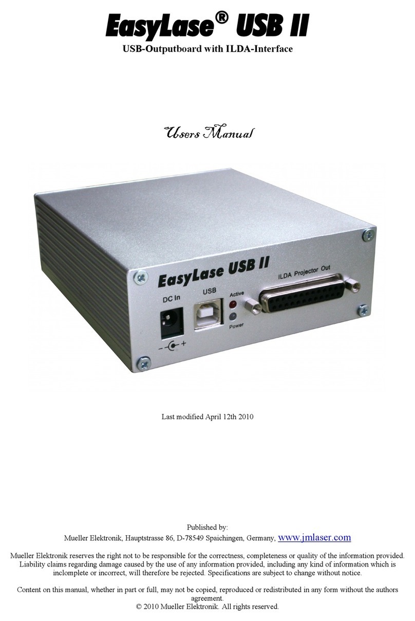
Mueller Elektronik
Mueller Elektronik EasyLase USB II user manual
GUILCOR
GUILCOR AR006712 instruction manual
Soyal
Soyal AR-721U user guide
ROC
ROC pH/ORP-5500 Series instruction manual
Lattice Semiconductor
Lattice Semiconductor MachXO2 Series Programming and Configuration Usage Guide

Bosch
Bosch HPC Installation, operation and maintenance manual
