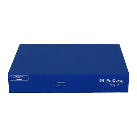
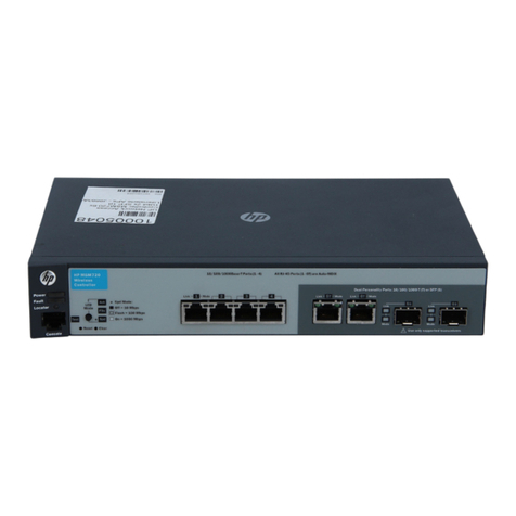
HP ProCurve MSM760 User manual

HP MSM760 Controllers Quickstart
This document describes how to install the MSM760 Access Controller (J9421A), and the MSM760 Premium
Mobility Controller (J9420A). These products are hereafter referred to as controller. The controller works
with HP 802.11n and 802.11ac access points to deliver a high-performance networking solution. For a list
of supported APs, see the HP MSM7xx Controllers Release Notes.
For additional installation information, and instructions on how to initially configure the controller, see the
HP MSM760 Controllers Installation Guide.
Hardware overview
Figure 1 MSM760 front view
1 2
3 4 5 6 7
5. Keypad (not used)1. Power, Fault, and Locator LEDs
6. USB port (not used)2. Ethernet Ports: 1=Internet, 2=LAN
7. Ethernet LEDs3. Console port
4. LCD display
Package contents
Controller, console cable, two mounting brackets, eight 8 mm screws, four 5/8 inch screws, four rubber
feet, power cord, and documentation.
LCD display
The LCD displays the following:
•The controller type, either Mobility Controller or Access Controller.
•The maximum number of supported APs, as defined by the installed license.
•The IP address of the Internet port. (Until the controller receives its IP address from a DHCP server, the
address displays as: 0.0.0.0)
During start up, the LCD displays a system booting message.
*5998-7942*
© Copyright 2014, 2015 Hewlett-Packard Development Company, L.P.
Printed in China
The information in this document is subject to change without notice.
HP Part Number: 5998-7942
Published: June 2015
Edition: 1

Ports
Controller console port: A standard serial port with an RJ-45 connector. To connect to a computer, use the
supplied DB-9 to RJ-45 console cable.
Ethernet ports: Two auto-sensing 10/100/1000 Ethernet ports with RJ-45 connectors. Connector 1 (left):
Internet port and connector 2 (right): LAN port.
MAC address
The MAC address of the Internet port is printed on the front of the controller. The MAC address of the LAN
port is the Internet port MAC address plus 1.
LEDs
The following table indicates the function of the status LEDs. See Figure 1 (page 1) for the location of the
LEDs.
DescriptionStateLED
The controller has no power.OffPower (green)
The controller is starting up. If the power LED continues to flash after several minutes, the firmware
failed to load. Reset or power cycle the controller. If this condition persists, contact technical
support.
Flashing
The controller is fully operational.On
The normal state, it indicates that there are no fault conditions on the controller.OffFault (orange)
A fault has occurred on the controller.Flashing
On briefly at the beginning of the self-test after the controller is powered on or reset. If it remains
on, the controller has encountered a fatal hardware failure, or has failed its self-test. For more
information, see the HP MSM760 Controllers Installation Guide.
On
The locator LED is used to locate a specific controller in a group of equipment, typically a rack.
The LED remains on until it is manually turned off.
OnLocator (blue)
The normal state.Off
No Ethernet link has been established.OffEthernet LEDs
nl
(right edge) Transmit/receive activity is occurring.Flashing
An Ethernet link has been established, but there is no transmit/receive activity.On
Link speed 10 MbpsOffEthernet LEDs
nl
(left edge) Link speed 100 MbpsGreen
Link speed 1000 Mbps (gigabit)Orange

Important information to read before installing
Observe the following precautions when installing the controller:
WARNING!
•Ensure that the rack or cabinet is adequately secured to prevent it from becoming unstable, or
falling over.
•Install products as low as possible in a rack or cabinet, with the heaviest devices at the bottom
and progressively lighter devices installed above.
•For safe operation, only install the controller horizontally, with the bottom side down.
CAUTION:
•Ensure the power source circuits are properly grounded, and use the power cord supplied with
the controller to connect it to the power source.
•If your installation requires a different power cord than the one supplied with the controller, be
sure to use a power cord displaying the mark of the safety agency that defines the regulations
for power cords in your country. The mark is your assurance that the power cord can be used
safely with the controller.
•When installing the controller, the AC outlet should be near the controller and should be easily
accessible in case the controller must be powered off.
•Ensure that the controller does not overload the power circuits, wiring, and over-current protection.
To determine the power supply circuit load, add the ampere ratings of all devices installed on
the circuit including the controller, and compare the total with the rating limit for the circuit. The
maximum ampere ratings are typically printed on the devices near the AC power connectors.
•Do not install the controller in an environment where the operating ambient temperature might
exceed 40°C (104°F).
•Ensure the air flow around the sides and back of the controller is not restricted.
Installation
The controller is shipped with an accessory kit that includes brackets for installation in a standard 19-inch
telco rack or an equipment cabinet, and rubber feet that can be attached to the controller for installation
on a shelf or other horizontal surface. Although the brackets are designed to allow a device to be mounted
in a variety of locations and orientations, you must install the controller horizontally.
Prepare the installation site
•Cabling infrastructure—Ensure the cabling infrastructure meets the necessary network specifications.
Cable type: Use Category 5 or better, 100-ohm unshielded twisted-pair (UTP) or shielded twisted-pair
(STP) balanced cable. For 1000 Mbps operation, HP recommends Category 5e or better.
Length limit: 100 meters

NOTE: The controller is compatible with the IEEE 802.3ab standard including the Auto
MDI/MDI-X feature, which allows use of either straight-through or crossover twisted-pair cables
for connecting to any network devices including end nodes, such as computers, or to other
switches, hubs, and routers.
For 1000 Mbps operation, all four wire pairs are used for data transmission.
•Installation location—Before installing the controller, plan its location relative to other devices and
equipment, and consider the following:
•The front of the controller requires at least 7.6 cm (3 inches) of space for the twisted-pair cabling.
•The back of the controller requires at least 3.8 cm (1.5 inches) of space for the power cord.
•The sides of the controller require at least 7.6 cm (3 inches) for cooling, except if the controller is
installed in an open EIA/TIA rack.
Installing the controller
After determining the configuration and preparing the site, mount the controller in a stable location. The
controller can be installed in a rack or cabinet, or placed on a table or shelf.
Mounting the controller in a rack or cabinet
The controller can be mounted in any EIA-standard 19-inch telco rack or communication equipment cabinet.
IMPORTANT: Equipment Cabinet Note
The four 12-24 screws supplied with the controller have the correct threading for standard EIA/TIA
open 19-inch racks. If you are installing the controller in an equipment cabinet, such as a server
cabinet, use the clips and screws that came with the cabinet instead of the 12-24 screws that are
supplied with the controller.
Before performing the following procedure, determine which four holes you will be using in the cabinet
and install all four clips.
1. Use a #1 Phillips (cross-head) screwdriver to attach the mounting brackets to the controller with the
included 8-mm M4 screws.
Figure 2 Controller with mounting brackets

2. Hold the controller with attached brackets up to the rack and move it vertically until rack holes line up
with the bracket holes, then insert and tighten the four number 12-24 screws to secure the brackets to
the rack.
Figure 3 Rack-mount installation
Horizontal surface mounting
Attach the supplied rubber feet to the four corners on the bottom of the controller within the embossed angled
lines. Place the controller on a table or other sturdy horizontal surface in an uncluttered area. You may want
to secure the networking cables and the power cord to a table leg or other part of the surface structure to
reduce the risk of tripping over the cords.
CAUTION: Make sure the air flow is not restricted around the sides and back of the controller.
Restarting the controller
The controller can be restarted by disconnecting, and then reconnecting the power cord, or by using its
management tool.
Resetting to factory defaults
HP recommends that you use the controller web interface to reset the controller to factory defaults as described
in the HP MSM760 Controllers Installation Guide
Support and other resources
For worldwide technical support information, see the HP support website at www.hp.com/support.
The HP MSM7xx Controllers Configuration Guide, the HP MSM760 Controllers Installation Guide, and
other related documentation is available on the Manuals page of the HP Support Center website at
www.hp.com/support/manuals. In the Find an HP product by search box, enter MSM760, and then click
GO. Also see the HP Networking website at www.hp.com/networking/.
Regulatory information
For important information, see the Safety, Compliance, and Warranty Information that shipped with your
controller. Also see Safety and Compliance Information for Server, Storage, Power, Networking, and Rack
Products, available at http://www.hp.com/support/Safety-Compliance-EnterpriseProducts.

Belarus Kazakhstan Russia marking
Manufacturer and Local Representative Information
Manufacturer’s information:
•Hewlett-Packard Company, 3000 Hanover Street, Palo Alto, California 94304, U.S.
Local Representative information Russian:
•HP Belarus: ИООО «Хьюлетт-Паккард Бел», 220030, Беларусь, г. Минск, ул. Интернациональная,
36-1, офис 722-723, тел.: +375 (17) 392 28 18, факс: +375 (17) 392 28 21
•HP Kazakhstan: ТОО «Хьюлетт-Паккард (К), 050040, Казахстан, г. Алматы, Бостандыкский район,
ул. Тимирязева, 28В, 1 этаж, тел./факс: +7 (727) 355 35 50, +7 (727) 355 35 51
•HP Russia: ЗАО “Хьюлетт-Паккард А.О.”, 125171, Россия, г. Москва, Ленинградское шоссе, 16А,
стр.3, тел/факс: +7 (495) 797 35 00, +7 (495) 287 89 05
Local Representative information Kazakh:
•HP Kazakhstan: ЖШС «Хьюлетт-Паккард (К)», Қазақстан, Алматы қ., Бостандық ауданы, Тимирязев
к-сі, 28В, тел./факс: +7 (727) 355 35 50, +7 (727) 355 35 51
Manufacturing Date – The manufacturing date is included in the product serial number, CCYMPPPZZZ (HP
serial number format for this product). The manufacturing date is indicated by YM in the serial number,
where Yindicates the year counting from within each new decade, with 2010 as the starting point, and M
is the month when the unit was manufactured. For example, 3A would indicate 3for 2013 and Afor the
month of November. Following this convention, 2010 is indicated by 0, 2011 by 1, 2012 by 2, 2013 by
3, and so forth. Months start at 1for January, 2for February, up to 9for September. 0(zero) is used for
October, Afor November, and Bfor December.
Дата изготовления – Дата изготовления включена в серийный номер изделия, CCYMPPPZZZ (формат
серийного номера HP для данного изделия). Дата изготовления указана как YM в серийном номере, где
Yсоответствует году с началом отсчета в каждом новом десятилетии, начиная с 2010, а Mсоответствует
месяцу изготовления устройства. Например, в обозначении 3A цифра 3соответствует 2013 году, а A
обозначает ноябрь. В соответствии с данным принятым обозначением, 2010 год указывается как 0, 2011
– как 1, 2012 – как 2, 2013 – как 3и т. д. Месяцы обозначаются как 1(январь), 2(февраль) и т. д. до
9(сентябрь). 0(ноль) обозначает октябрь, Aобозначает ноябрь, а Bобозначает декабрь.
Жасалған күні – Жасалған күні CCYMPPPZZZ (осы өнімге арналған HP сериялық нөмірінің пішімі)
пішіміндегі өнімнің сериялық нөмірінде қамтылады. Жасалған күні сериялық нөмірдегі YM əріптерімен
көрсетіледі. Yəрпі 2010 жылдан басталатын жəне əр он жылдан бастап есептелетін жылды көрсетеді
жəне Məрпі құрылғының жасалған айын білдіреді. Мысалы, 3A таңбалары келісіні білдіреді: 3– 2013
жылды жəне Aқараша айын көрсетеді. Бұл əдіс бойынша, 2010 жыл 0санымен, 2011 жыл 1санымен,
2012 жыл 2санымен, 2013 жыл 3санымен жəне т.т. көрсетіледі. Айларды 1 мен 9 аралығындағы
сандар көрсетеді:1саны қаңтар айы үшін, 2саны ақпан айы үшін жəне 9саны қыркүйек айы үшін.
0(нөл) саны қазан айы үшін, Aəрпі қараша айы үшін жəне Bəрпі желтоқсан айы үшін қолданылады.
Ukraine RoHS material content declaration
Обладнання відповідає вимогам Технічного регламенту щодо обмеження використання деяких небезпечних
речовин в електричному та електронному обладнанні, затвердженого постановою Кабінету Міністрів
України від 3 грудня 2008 № 1057
Specifications
H: 4.2 cm (1.64 inch), W: 44.3 cm (17.42 inch), D: 39 cm (15.4 inch)Dimensions
6.1 kg (13.45 lb)Weight
100–127/200–240 voltsAC voltage1
2 A/1 AMaximum current
50/60 HzFrequency range
Operating: 5°C to 40°C (41°F to 122°F), Non-operating: -40°C to 65°C (-40°F to 149°F)Temperature
Operating: 15% to 80% at 40°C (104°F), Non-operating: 20% to 90% at 65°C (149°F)Relative humidity
nl
(non-condensing)
Operating: 2 km (6,500 ft), Non-operating: 4.6 km (15,000 ft)Maximum altitude
Noise Emission LwA=52 dB at virtual work space according to DIN 45635 T.19Acoustic
The 10/100/1000 Mbps RJ-45 twisted-pair ports are compatible with IEEE 802.3ab 1000Base-T,
IEEE 802.3u 100Base-TX, and IEEE 802.3 10Base-T standards.
Connectors
Complies with EN60950-1/IEC 60950-1, CSA 22.2 No. 60950-1, and UL 60950-1 standards.Safety
1The controller automatically adjusts to any voltage between 100–127 and 200–240 volts at either 50 or 60 Hz.
Other manuals for ProCurve MSM760
1
Table of contents
Other HP Controllers manuals

HP
HP ProCurve 800 Manual

HP
HP HPE VAN SDN Controller 2.7 Service manual

HP
HP Smart Array P800 User manual

HP
HP P420 User manual

HP
HP MSM775 zl User manual

HP
HP A9890A - Smart Array 6402/128 RAID... User manual

HP
HP Compaq Presario,Presario 4400 Guide

HP
HP MSA 2040 User manual

HP
HP StorageWorks 2312 User manual

HP
HP HSG80 - StorageWorks RAID Array Controller User manual