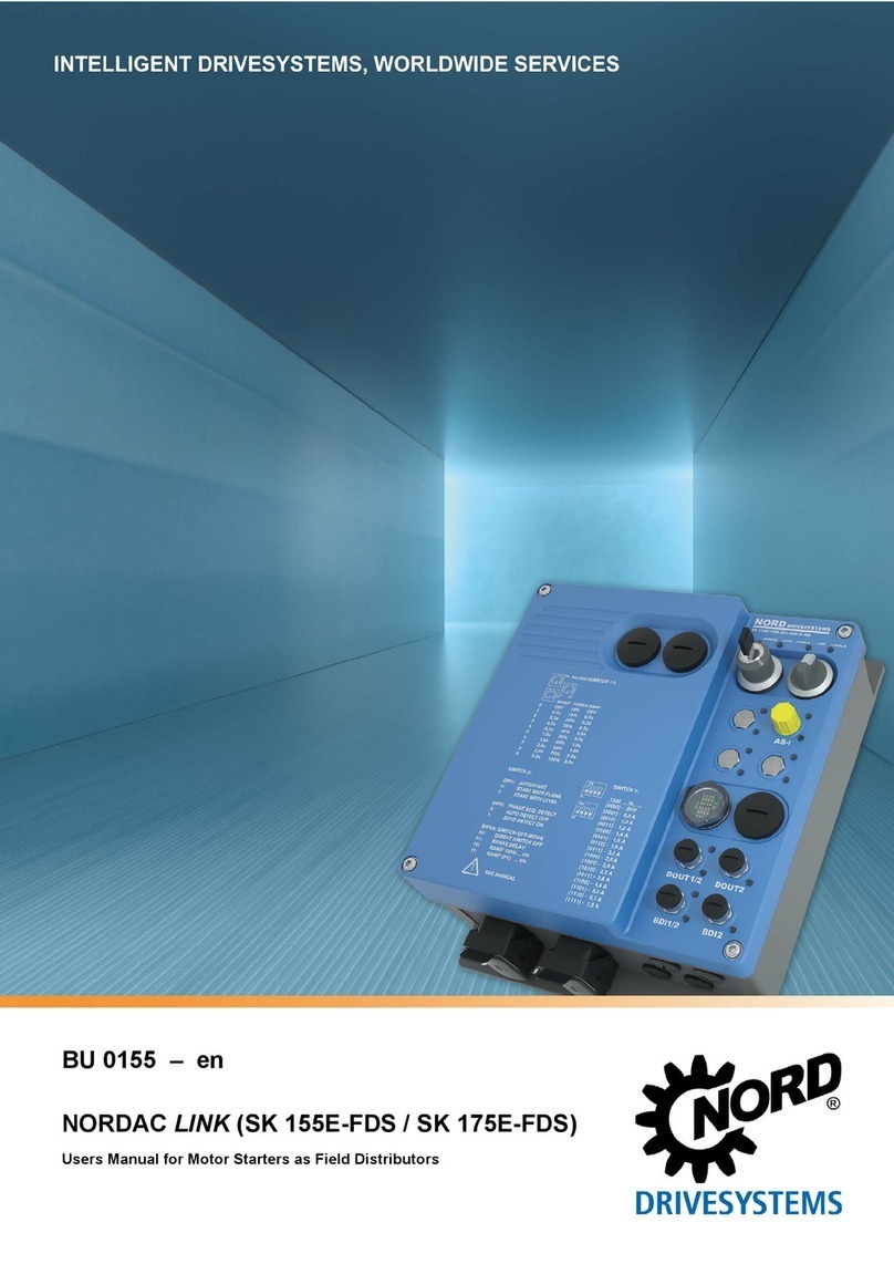
Nord Drivesystems NORDAC LINK SK 155E-FDS Series User manual

BU 0155 – en
NORDAC LINK (SK 155E-FDS / SK 175E-FDS)
Users Manual for Motor Starters as Field Distributors

NORDAC LINK (SK 155E-FDS / SK 175E-FDS) – Users Manual for Motor Starters as Field Distributors
2 BU 0155 en-1618
Pos: 3/ Anl ei tung en /El e ktroni k /FU und St ar ter / 0. Prol og /D o ku me nt ati on - Ver sio ns li st e [ BU 015 5 F D S] @ 21\mod_1519633903111_388.docx@ 2407818@ @ 1
Documentation
Title:
BU 0155
Order – No.:
6071502
Series:
SK 1x5E-FDS
Device series:
SK 155E-FDS, SK 175E-FDS
Device types:
SK 1x5E-FDS-301-340-xxx 0.55 – 3.0 kW, 3~ 380-500 V
Version list
Title,
Date
Order number Device
software
version
Remarks
BU 0155,
September
2016
6071502 / 3916
V 1.0 R0
First edition, for pilot series devices (field test)
BU 0155,
July 2017
6071502 / 2817
V 1.0 R2
• Names of option slots on H1, H2 and H3 changed
• Power connection plug and M12 plug connector
Correction of various pin connections
• Parameter P434, function 21 supplemented
• Parameters P203, P570: Value range changed
• Potentiometers P1 and P2: Setting values changed
• DIP switch S1: Setting values changed
• CE Declaration of Conformity supplemented
• Various other corrections
BU 0155,
April 2018
6071502 / 1618 V 1.0 R2 Among other things
• General corrections
• Adaptation of safety information
• Revision of warnings and hazard notes
• Inclusion of UL data
• AS-interface – Supplementation of single slave
"AXS"
• Supplementation of connection accessories
• Update of EU Declaration of Conformity
Table 1: Version list
Pos: 4/ Al lg emei n/ All ge mei ngül tig e M odul e/---------Seitenumbruch kompakt--------- @ 1 3\mod_1476369695906_0.docx @ 2265495 @ @ 1

Copyright notice
BU 0155 en-1618 3
Pos: 5/ Al lg emei n/ All ge mei ngül tig e M odul e/U r he ber rec hts ver mer k @ 5\mod_1410955083459_388.docx @ 150427@ @ 1
Copyright notice
As an integral component of the device described here, this document must be provided to all
users in a suitable form.
Any editing or amendment or other utilisation of the document is prohibited.
Pos: 6/ Al lg emei n/ All ge mei ngül tig e M odul e/H er a usge b er @ 0\mod_1325779078002_388.docx@ 5270@ @ 1
Publisher
Getriebebau NORD GmbH & Co. KG
Getriebebau-Nord-Straße 1 • 22941 Bargteheide, Germany • http://www.nord.com/
Fon +49 (0) 45 32 / 289-0 • Fax +49 (0) 45 32 / 289-2253
Member of the NORD DRIVESYSTEMS Group
===Endeder ListefürT extmarkeCopyright===

NORDAC LINK (SK 155E-FDS / SK 175E-FDS) – Users Manual for Motor Starters as Field Distributors
4 BU 0155 en-1618

Table of Contents
BU 0155 en-1618 5
Pos: 8/ A ll ge mei n/ S t euer mod ul e/ In h alts ver zeic hni s @ 0\mod_1317978518480_388.docx@ 4 078 @ @ 1
Table of Contents
=== En de der List e f ür Te xtm ar ke I nhal ts v erz ei ch ni s == =
1General.........................................................................................................................................................9
1.1 Overview ..........................................................................................................................................10
1.2 Delivery............................................................................................................................................11
1.3 Scope of delivery..............................................................................................................................12
1.4 Safety, installation and operating instructions..................................................................................13
1.5 Warning and hazard information......................................................................................................17
1.5.1 Warning and hazard information on the product.................................................................17
1.5.2 Warning and hazard information in the document ..............................................................18
1.6 Standards and approvals .................................................................................................................19
1.6.1UL and cUL (CSA) approval ...............................................................................................19
1.7 Type code / nomenclature................................................................................................................22
1.7.1 Type plate...........................................................................................................................22
1.7.2 Field distribution type codes ...............................................................................................24
1.8 Version with protection class IP65 ...................................................................................................24
2Assembly and installation ........................................................................................................................25
2.1 Installation........................................................................................................................................26
2.2 Option slots and equipment variants................................................................................................27
2.2.1 Option slots.........................................................................................................................27
2.2.1.1 Connection level 27
2.2.1.2 Control level 28
2.2.1.3 Maintenance switch level 28
2.2.2 Configuration variants.........................................................................................................29
2.2.2.1 Configurable options 29
2.2.2.2 Configuration of option slots on the control level 30
2.2.2.3 Configuration of option slots on the connection level 33
2.2.2.4 Configuration of the option slot for the maintenance switch level 36
2.3 Electrical Connection .......................................................................................................................37
2.3.1 Wiring guidelines ................................................................................................................37
2.3.2 Electrical connection of power unit .....................................................................................39
2.3.2.1 Mains connection (L1, L2, L3, PE) 39
2.3.2.2 Motor cable (U, V, W, PE) 40
2.3.2.3 Electromechanical brake 40
2.3.3 Electrical connection of the control unit ..............................................................................41
2.3.3.1 Control connection details 43
3Display, operation and options ................................................................................................................45
3.1 Indicator lights..................................................................................................................................46
3.2 Control and parametrisation options ................................................................................................47
3.2.1 Control and Parametrisation Boxes / Software...................................................................47
4Commissioning .........................................................................................................................................49
4.1 Factory settings................................................................................................................................49
4.2 Starting up the device ......................................................................................................................49
4.2.1 Connection .........................................................................................................................50
4.2.2 Configuration ......................................................................................................................50
4.2.2.1 Parametrisation 51
4.2.2.2 Potentiometers P1 to P3 52
4.2.2.3 DIP switches (S1, S2) 53
4.2.2.4 Overview of switch-off modes 54
4.3 AS Interface (AS-i) ...........................................................................................................................56
4.3.1 The bus system ..................................................................................................................56
4.3.2 Features and technical data ...............................................................................................57
4.3.3 Bus structure and topology.................................................................................................58
4.3.4 Commissioning...................................................................................................................60
4.3.4.1 Connection 60
4.3.4.2 Displays 60
4.3.4.3 Configuration 61
4.3.4.4 Addressing 63
4.3.5 Certificate ...........................................................................................................................64
4.4 PROFIBUS DP.................................................................................................................................65

NORDAC LINK (SK 155E-FDS / SK 175E-FDS) – Users Manual for Motor Starters as Field Distributors
6 BU 0155 en-1618
4.4.1 The bus system ..................................................................................................................65
4.4.2 Features .............................................................................................................................65
4.4.3 Commissioning...................................................................................................................66
4.4.3.1 Connection 66
4.4.3.2 Displays 66
4.4.3.3 Configuration 66
4.4.3.4 Addressing 68
5Parameter...................................................................................................................................................69
5.1 Parameter overview .........................................................................................................................71
5.2 Description of parameters................................................................................................................72
5.2.1 Operating displays..............................................................................................................74
5.2.2 Basic parameters................................................................................................................75
5.2.3 Motor data ..........................................................................................................................78
5.2.4 Speed control .....................................................................................................................79
5.2.5 Control terminals ................................................................................................................81
5.2.6 Additional parameters.........................................................................................................85
5.2.7 Information..........................................................................................................................89
6Operating status messages .....................................................................................................................94
6.1 Display of messages........................................................................................................................94
6.2 Diagnostic LEDs on device ..............................................................................................................95
6.3 Messages.........................................................................................................................................96
6.4 FAQ operational problems ...............................................................................................................99
7Technical data .........................................................................................................................................100
7.1 General data Motor starter.............................................................................................................100
7.2 Electrical data ................................................................................................................................101
7.2.1 Electrical data...................................................................................................................101
8Additional information ............................................................................................................................102
8.1 Electromagnetic compatibility (EMC) .............................................................................................102
8.1.1 General Provisions ...........................................................................................................102
8.1.2 EMC evaluation - EN 55011-1 (environmental standard) .................................................103
8.1.3 EMC of device ..................................................................................................................104
8.1.4 EU Declaration of Conformity ...........................................................................................105
8.2 Operation on the FI circuit breaker.................................................................................................106
8.3 Trigger classes (I²t) ........................................................................................................................106
8.4 Switch-on cycle ..............................................................................................................................107
8.5 Connection accessories.................................................................................................................108
8.5.1 Power connections - mating connectors...........................................................................108
8.5.2 M12 Y distributor ..............................................................................................................109
8.5.3 Motor cable.......................................................................................................................109
9Maintenance and servicing information................................................................................................110
9.1 Maintenance Instructions ...............................................................................................................110
9.2 Service notes .................................................................................................................................111
9.3 Abbreviations .................................................................................................................................112

List of illustrations
BU 0155 en-1618 7
Pos: 10 / All g e mei n /S te u er m odul e/ Ab bil d ungs v erz ei ch nis @ 0\mod_1317978515699_388.docx @ 3917@ @ 1
List of illustrations
=== En de der List e f ür Te xtm ar ke Ab bi ldu ng s v erz eic h ni s == =
Figure 1: SimpleBox, handheld, SK CSX-3H......................................................................................................... 47
Figure 2: ParameterBox, handheld, SK PAR-3H................................................................................................... 47
Figure 3: Explanation of parameter description ..................................................................................................... 72
Figure 4: Trigger class curves ............................................................................................................................. 106
Figure 5: Trigger times for warm operating state (with previous: I = continuous Inenn) ......................................... 107

NORDAC LINK (SK 155E-FDS / SK 175E-FDS) – Users Manual for Motor Starters as Field Distributors
8 BU 0155 en-1618
Pos: 12 /Al lg e mei n/ Ste u erm o dul e/T ab ell en ver zei c hni s @ 0\mod_1317978519199_388.docx @ 4124@ @ 1
List of tables
=== En de der List e f ür Te xtm ar ke Ta b ell e nver z eic hni s ===
Table 1: Version list................................................................................................................................................. 2
Table 2: Additional features................................................................................................................................... 11
Table 3: Warning and hazard information on the product...................................................................................... 17
Table 4: Standards and approvals......................................................................................................................... 19
Table 5: Configuration - comparison of hardware and software adaptation........................................................... 50
Table 6: Parameters and functions depending on P130........................................................................................ 51
Table 7: FAQ operational problems....................................................................................................................... 99
Table 8: EMC - Limit class in accordance with EN 55011 ................................................................................... 103
Table 9: Overview according to product standard EN 60947-4-2 ....................................................................... 104
Pos: 15 /A nl eitu ng e n/ El ek tr oni k/FU und S tar t er / 1. Al lg e mei n es/ A ll ge mei nes (Ü ber sc hri ft) @ 6\mod_1424437508320_388.docx @ 204378@ 1 @ 1

1 General
BU 0155 en-1618 9
1 General
Pos: 16 /A nl eitu ng e n/ El ek tr oni k/FU und S tar t er / 1. Al lg e mei n es/ A ll ge mei nes _I nhal t [ SK 1 x5 E, SK 1 x5 E-FD S] @ 6\mod_1429699576229_388.docx@ 212642@ @ 1
The SK 1x5E-FDS series is based on the tried and tested NORD platform. The devices are
characterised by their compact design and their optimum operational characteristics, and have uniform
parametrisation.
Due to dual phase control, not only a pure motor start, but also a soft start is possible. The phase
control process was selected so that the resulting harmonic torques are kept as low as possible. A
comprehensive spectrum of monitoring functions rounds off the range.
Due to the numerous setting options, any three-phase synchronous motor can be controlled.
The motor starter is basically intended for a three-phase mains connection. The power range is from
0.25 kW to 3.0 kW.
This series of devices can be adapted to individual requirements by means of modular assemblies.
This manual is based on the device software specified in the version list (see P707). If the motor
starter uses a different software version, this may cause differences. If necessary, the current manual
can be downloaded from the Internet (http://www.nord.com/).
Additional descriptions exist for optional functions and bus systems (http://www.nord.com/).
Information Accessories
Changes may also be made to the accessories that are mentioned in the manual. Current details of these are
included in separate data sheets, which are listed under www.nord.com under the heading Documentation →
Manuals → Electronic drive technology → Techn. Info / Data sheet. The data sheets available at the date of
publication of this manual are listed by name in the relevant sections (TI ...).
The different versions of the device series also result in different functionality (e.g.: with integrated AS
Interface or with integrated PROFIBUS DP interface).
In the simplest configuration, all of the most important parameters can be set using up to four
potentiometers and four DIP switches, even without a PC or a control unit. LEDs are provided for the
diagnostics of the operating status. The use of a control module is therefore not absolutely necessary.
Pos: 17 /A nl eitu ng e n/ El ek tr oni k/FU und S tar t er / 1. Al lg e mei n es/ A ll ge mei nes _I nhal t_ Er gän z ung 1_ dez e ntral [ SK xxxE-F D S] @ 1 1\mod_1462786423168_388.docx @ 319260 @ @ 1
A typical feature of this frequency inverter series is their installation close to the motor, e.g. on the wall
or on a machine frame.
All electrical connections (power connections and control connections) are made with plug connectors.
This considerably simplifies the installation of the frequency inverter and opening the FI is not
necessary.
In order to obtain access to all parameters, the internal RS232 interface (access via RJ12 connection)
can be used. Access to the parameters is made e.g. via an optional SimpleBox or ParameterBox.
Pos: 18 /A nl eitu ng e n/ El ek tr oni k/FU und S tar t er / 1. Al lg e mei n es/ A ll ge mei nes _I nhal t_ Er gän z ung 2_ dez e ntral [ SK 1 x5E , SK 1x 5E-FD S] @ 8\mod_1438930205982_388.docx@ 235628@ @ 1
The parameter settings modified by the owner/operator must be saved in the Flash memory of the
device (P550). Otherwise the changed parameter settings would be lost when the device was
switched off.
Pos: 19 /A nl eitu ng e n/ El ek tr oni k/FU und S tar t er / 1. Al lg e mei n es/ A ll ge mei nes _I nhal t_ Er gän z ung 3_ dez e ntral [ SK 1 x5E-F D S] @ 13\mod_1472651101916_388.docx @ 345500@ @ 1
The frequency inverter is configured according to the customer's individual requirements.
Configuration is therefore performed at the factory. Retrofitting of options or conversions are not
intended.

NORDAC LINK (SK 155E-FDS / SK 175E-FDS) – Users Manual for Motor Starters as Field Distributors
10 BU 0155 en-1618
Information
The frequency inverter must not be opened.
The frequency inverter must not be opened at any time during its service life. As in normal operation, all
assembly, installation and commissioning is only carried out with the FI closed.
• Assembly is carried out via freely accessible mounting holes.
• Electrical connections are made exclusively with plug connectors..
• Operating settings are made by changing parameters or with DIP switches and potentiometers. Access to
these elements or for connecting a parameterisation tool is via blank plugs. These blind plugs may only be
removed for work associated with commissioning and must then be properly refitted.
• Diagnostic LEDs to indicate switching and operating states are externally visible.
Pos: 20 /A nl eitu ng en/ Ele ktr oni k/F U u nd S tar ter /1. Allg e mein es/Ü ber bli c k -1- [ SK 1 xx E-FDS ] @ 1 1\mod_1458746647822_388.docx @ 315220@ 255@ 1
1.1 Overview
This manual describes all of the possible functions and equipment. The configuration and functionality
are limited according to the type of device. SK 175E-FDS frequency inverters have additional
integrated characteristics for the maximum configuration.
Basic characteristics
• Wall mounting close to the motor.
• 5 digital inputs a), b)
• 2 digital outputs b)
• Separate temperature sensor input (TF+/TF-) b)
• Motor overload protection (I2t triggering characteristic in accordance with EN 60947) This means
that a motor protection switch is not needed, merely an input fuse!
• Mains and motor phase failure monitoring
• Flux monitoring (minimum current monitoring)
• Automatic phase sequence detection
• Permissible ambient temperature -25 °C to 50 °C (please refer to the technical data)
• Integrated EMC mains filter for Class A limit values
• 2 x DIP switches and 3 x potentiometers for configuration
• Diagnostic LEDs (incl. signal status DIs/ DOs)
• RS232 / RS485 interface via RJ12 plug connector, alternatively USB (only RS232)
• 24 V DC control voltage
– Must be provided via a plug connector, or
– Can be provided by the FI (only with option –HVS).
It is also possible to connect an external 24 V DC voltage supply via an optional plug connector
in order to supply a high power peripheral (e.g. actuator).
• Integrated PLC (BU 0550)
a) If necessary, individual inputs can be defined at the factory by use
of certain optional modules.
b)
Connection is only possible with optional plug connectors.
Additional features
There are two versions of the frequency inverters (-ASI) with integrated AS interface and (-PBR) with
integrated PROFIBUS DP.
Differences between the individual versions (SK 155E-FDS / SK 175E-FDS) are summarised in the
following table and are described in this manual.

1 General
BU 0155 en-1618 11
Feature 155E-
ASI
155E-
PBR
175E-
ASI
175E-
PBR
Soft start function
x
x
x
x
Reversing function x x
AS interface (4I / 4O)
ASI
ASI
PROFIBUS-DP (4I / 4O)
PBR
PBR
Table 2: Additional features
Pos: 21 /A nl eitu ng en/ Ele ktr oni k/F U u nd S tar ter /1. Allg e mein es/Ü ber bli c k -2- [ SKxxxE-FD S] @ 1 1\mod_1462800436315_388.docx @ 319479 @ 5 @ 1
Optional features
The FI can be individually adapted to the drive task. For this, a comprehensive selection of interfaces,
plug connections and control elements are available, which can be used during the manufacture of the
FI according to the customer's requirements.
Depending on the configuration, the meaning of the individual LEDs, function or assignment of
individual plug connectors or the function of control elements (e.g. switches) may differ. The possible
combinations will be illustrated and explained in the course of this manual. The individual configuration
of the FI can be identified using the type plate and can be compared with the details in the manual.
Pos: 22 /A nl eitu ng e n/ El ek tr oni k/FU und S tar t er / 1. Al lg e mei n es/ Li e fer ung @ 0\mod_1325780242208_388.docx@ 5339@ 2 @ 1
1.2 Delivery
Check the equipment immediately after delivery / unpacking for transport damage such as
deformation or loose parts.
If there is any damage, contact the carrier immediately and carry out a thorough assessment.
Important! This also applies even if the packaging is undamaged.
Pos: 23 /All ge mei n/Al lge mei ng ültig e M odul e/---------Sei te num bruc h kom pak t --------- @ 13 \mod_1476369695906_0.docx @ 2265495@ @ 1

NORDAC LINK (SK 155E-FDS / SK 175E-FDS) – Users Manual for Motor Starters as Field Distributors
12 BU 0155 en-1618
Pos: 24 /A nl eitu ng e n/ El ek tr oni k/FU und S tar t er / 1. Al lg e mei n es/ Li e fer u mfa ng _ 0 1_(Ü bers c hri ft) [BU0135, 0180,0200,-FD S] @ 1\mod_1341396112550_388.docx@ 29151@ 2 @ 1
1.3 Scope of delivery
Pos: 25 /A nl eitu ng e n/ El ek tr oni k/FU und S tar t er / 1. Al lg e mei n es/ S ich er h eits - u nd Inst allati onshi nweis e und War n- Gef ahr en hi nw ei s e/ ne u/ War n- u nd G ef ahr enhi n wei s e/ AC HTUNG - D efe kt am G erä t ( durc h Z ub ehör ) @ 19\mod_1511271363545_388.docx@ 2372025@ @ 1
NOTICE Defect in the device
Use of unapproved accessories and options (e.g. options from other device series (SK CSX-0)) may result in
defects of the interconnected components.
Only use options and accessories which are explicitly intended for use with this device and are stated accordingly
in this manual.
Pos: 26 /A nl eitu ng e n/ El ek tr oni k/FU und S tar t er / 1. Al lg e mei n es/ Li e fer u mfa ng _ 0 2 [ SK xx xE-FD S] @ 1 1\mod_1464611335501_388.docx @ 324820@ @ 1
Standard version: • IP65 version
• Operating instructions as PDF file on CD ROM including NORD CON, (PC
parametrisation software)
Pos: 27.1 /A nl eitu ng e n/ El ek tr oni k/FU und S tar t er / 1. Al lg e mei n es/ Li ef er um fa ng / Lief er u m fa ng Z ub e hör [S K xx xE-F D S] @ 12\mod_1468246654664_388.docx@ 338032@ @ 1
Configurable options and accessories:
Designation Example Description
Pos: 27.2 /A nl eitu ng e n/ El ek tr oni k/FU und S tar t er / 1. Al lg e mei n es/ Li ef er um fa ng / Lief er u m fa ng Z ub e hör _0 1 _B edi en u ng [ SK xxxE-FDS] @ 12\mod_1466775948560_388.docx @ 332870 @ @ 1
Control and parametrisation options
Handheld parametrisation units
for temporary connection to the
FI
For commissioning, parametrisation and control
of the FI.
SK PAR-3H, SK CSX-3H
(Section 3.2 "Control and parametrisation
options ")
NORD CON
MS Windows ® - based
software
For commissioning, parametrisation and control
of the FI.
See www.nord.com
NORD CON
(Free download)
Pos: 27.3 /A nl eitu ng e n/ El ek tr oni k/FU und S tar t er / 1. Al lg e mei n es/ Li ef er um fa ng / Lief er u m fa ng Z ub e hör _1 1 _S on sti g es [ S K 1 xx E-FD S] @ 12\mod_1471423519349_388.docx@ 341190@ @ 1
Miscellaneous
Internal fuse module
Interface for protecting the individual device in
the event of "Daisy Chain" wiring (looping
through of mains voltage from one FI to the
next).
SK CU4-FUSE (TI 275271122)
SK CU4-FUSE-C (TI 275271622)
Pos: 27.4 /A nl eitu ng e n/ El ek tr oni k/FU und S tar t er / 1. Al lg e mei n es/ Li ef er um fa ng / Lief er u m fa ng Z ub e hör _1 2 _S oft w are [SK 1 x xE-F DS ] @ 18\mod_1496227769511_388.docx@ 2351764@ @ 1
Software (Free download)
NORD CON
MS Windows ® - based
software
For commissioning, parametrisation and control
of the device.
Refer to www.nord.com
NORD CON
ePlan macros
Macros for producing electrical circuit diagrams
In preparation
Device master data
Device master data / device description files for
NORD field bus options
NORD fieldbus files
Pos: 28 /All ge mei n/Al lge mei ng ültig e M odul e/---------Sei tenu mbruc h k om pak t --------- @ 13 \mod_1476369695906_0.docx @ 2265495@ @ 1

1 General
BU 0155 en-1618 13
Pos: 29.1 /A nl eitu ng e n/ El ek tr oni k/FU und S tar t er / 1. Al lg e mei n es/ S ich er h eits - u nd Inst allati onshi nweis e und Warn- G ef ahr en hin w eis e/ ne u/ Si ch er hei ts -, I ns t all a tio ns - und Anwendungshinweise_01[alle Geräte- für Ha n db ue ch er B U ... . ] @ 17\mod_1488973491253_388.docx @ 2333815@ 2 @ 1
1.4 Safety, installation and operating instructions
Pos: 29.2 /A nl eitu ng e n/ El ek tr oni k/FU und S tar t er / 1. Al lg e mei n es/ S ich er h eits - u nd Inst allati onshi nweis e und Warn- G ef ahr en hin w eis e/ ne u/ Si ch er hei ts -, I ns t all a tio ns - undAnwendungshinweise_02[alle Geräte] @ 12\mod_1466690028867_388.docx@ 332586@ @ 1
Before working on or with the device, please read the following safety instructions extremely carefully.
Please pay attention to all other information from the device manual.
Non-compliance can result in serious or fatal injuries and damage to the device or its surroundings.
These safety instructions must be kept in a safe place!
Pos: 29.3 /A nl eitu ng e n/ El ek tr oni k/FU und S tar t er / 1. Al lg e mei n es/ S ich er h eits - u nd Inst allati onshi nweis e und Warn- G ef ahr en hin w eis e/ ne u/ Si ch er hei ts - und Inst al la ti o nshi n w eis e - Einzelpunkte/1.Al lg emei n ( Sic her h eits hi nw eise) [S K 1 xx E-FDS] @ 2 0\mod_1515054240981_388.docx@ 237666 9 @ @ 1
1. General
Do not use defective devices or devices with defective or damaged housings or missing covers (e.g.
blind plugs). Otherwise, there is a risk of serious injury or death from electric shock.
Unauthorised removal of covers, improper use, incorrect installation or operation causes a risk of
serious personal injury or material damage.
During operation, depending on their protection class, devices may have live bare components as well
as hot surfaces.
The device operates with a dangerous voltage. Dangerous voltage may be present at the supply lines,
contact strips and PCBs of all connecting terminals (e.g. mains input, motor connection), even if the
device is not working or the motor is not rotating (e.g. caused by electronic disabling, jamming of the
drive or a short circuit at the output terminals).
The device is not equipped with a mains switch and is therefore always live when connected to the
power supply. Voltages may therefore be connected to a connected motor at standstill. An optional
mains connection outlet is also at mains voltage.
Even if the drive unit has been disconnected from the mains, a connected motor may rotate and
possibly generate a dangerous voltage.
If you come into contact with dangerous voltage such as this, there is a risk of an electric shock, which
can lead to serious or fatal injuries.
Power plug connectors must not be pulled out when they are connected to the power supply. Failure
to comply with this may cause arcing, which in addition to the risk of injury, also results in a risk of
damage or destruction of the device.
The fact that the status LED or other indicators are not illuminated does not indicate that the device
has been disconnected from the mains and is without voltage.
Metal components and the housing of power plug connectors may heat up to temperatures of more
than 70°C.
Touching these parts can result in local burns to the body parts concerned (cooling times and
clearance from neighbouring components must be complied with).
All work on the device, e.g. transportation, installation, commissioning and maintenance work must be
carried out by qualified experts (observe IEC 364 or CENELEC HD 384 or DIN VDE 0100 and
IEC 664 or DIN VDE 0110 and national accident prevention regulations). In particular, the general and
regional installation and safety regulations for work on high voltage systems (e.g. VDE) must be
complied with as must the regulations concerning correct use of tools and the use of personal
protection equipment.
During all work on the device, take care that no foreign bodies, loose parts, moisture or dust enter or
remain in the device (risk of short circuit, fire and corrosion).
Further information can be found in this documentation.
Pos: 29.4 /A nl eit ung e n/ El e kt ro ni k/FU und S tar t er / 1. Al l ge mei n es / Sic her h eit s- u nd Inst allati onshi nweis e und War n- Gefahr enhi n wei s e/ ne u/ Sic h er hei ts- u nd I ns t all a tio ns hi n wei se - Einzelpunkte/2. Q ual ifi zi ert es Fach per s onal (Si ch erh eit s hin wei s e) @ 1 2\mod_1466690573079_388.docx @ 332620@ @ 1
2. Qualified experts
For the purposes of these basic safety instructions, qualified personnel are persons who are familiar
with the assembly, installation, commissioning and operation of this product and who have the
relevant qualifications for their work.

NORDAC LINK (SK 155E-FDS / SK 175E-FDS) – Users Manual for Motor Starters as Field Distributors
14 BU 0155 en-1618
Furthermore, the device and the associated accessories may only be installed and started up by
qualified electricians. An electrician is a person who, because of their technical training and
experience, has sufficient knowledge with regard to
• switching on, switching off, isolating, earthing and marking power circuits and devices,
• proper maintenance and use of protective devices in accordance with defined safety standards.
Pos: 29.5 /A nl eitu ng e n/ El ek tr oni k/FU und S tar t er / 1. Al lg e mei n es/ S ich er h eits - u nd Inst allati onshi nweis e und Warn- G ef ahr en hin w eis e/ ne u/ Si ch er hei ts - und Inst al la ti o nshi n w eis e - Ei nz el pun kte /3 . B est imm ung sg e mäße Verw end ung – allg e m ein ( Si ch er h eits hi n wei s e) [ al le Star t er] @ 1 7\mod_1490340802581_388.docx@ 2336379 @ @ 1
3. Correct purpose of use – general
The Motor starters are devices for industrial and commercial plants for operating three-phase
asynchronous motors with squirrel-cage rotors.
The devices are components intended for installation in electrical systems or machines.
Technical data and information for connection conditions can be found on the rating plate and in the
documentation, and must be complied with.
The devices may only be used for safety functions which are described and explicitly approved.
CE-labelled devices fulfil the requirements of the Low Voltage Directive 2014/35/EU. The stated
harmonized standards for the devices are used in the declaration of conformity.
a. Supplement: Correct purpose of use within the European Union
When installed in machines, the devices must not be commissioned (i.e. commencement of
proper use) until it has been ensured that the machine fulfils the provisions of EC Directive
2006/42/EC (Machinery Directive); EN 60204-1 must also be complied with.
Commissioning (i.e. start-up of proper use) is only permitted if the EMC directive (2014/30/EU)
has been complied with.
b. Supplement: Correct purpose of use outside the European Union
The local conditions of the operator for the installation and commissioning of the device must be
complied with at the usage location (see also "a) Supplement: Correct purpose of use within the
European Union").
Pos:29.6/Anleitungen/Elektronik/FUund Starter / 1. Al lg e mei n es/ Si ch er h eits - u nd Instal lati onshi nweis e und Warn- G ef ahr en hin w eis e/ ne u/ Si ch er hei ts- u nd Inst al la ti o nshi n w eis e - Ei nz el p unk te/ 4. Lebe ns phas e n @ 19\mod_1508740334297_388.docx@ 2368381 @ @ 1
4. Phases of life
Pos: 29.7 /A nl eitu ng e n/ El ek tr oni k/FU und S tar t er / 1. Al lg e mei n es/ S ich er h eits - u nd Inst allati onshi nweis e und Warn- G ef ahr en hin w eis e/ ne u/ Si ch er hei ts - und Inst al la ti o nshi n w eis e - Ei nz el pun kte /4 _a. T r ans por t, Ei nl ager ung ( S ich erh eits hi nw eis e) @ 19\mod_1508761292824_388.docx @ 23690 21 @ @ 1
Transport, storage
The information in the manual regarding transport, storage and correct handling must be complied
with.
The permissible mechanical and climatic ambient conditions (see technical data in the manual for the
device) must be complied with.
If necessary, suitable, adequately dimensioned means of transport (e.g. lifting gear, rope guides) must
be used.
Pos: 29.8 /A nl eitu ng e n/ El ek tr oni k/FU und S tar t er / 1. Al lg e mei n es/ S ich er h eits - u nd Inst allati onshi nweis e und Warn- G ef ahr en hin w eis e/ ne u/ Si ch er hei ts - und Inst al la ti o nshi n w eis e - Ei nz el pun kte /4 _b. Aufst ell ung un d M ont age (Sic her hei tshi n wei se) @ 19 \mod_1508741535965_388.docx@ 2368416@ @ 1
Installation and assembly
The installation and cooling of the device must be implemented according to the regulations in the
corresponding documentation. The permissible mechanical and climatic ambient conditions (see
technical data in the manual for the device) must be complied with.
The device must be protected against impermissible loads. In particular, components must not be
deformed and/or insulation distances must not be changed. Touching of electronic components and
contacts must be avoided.
The device and its optional modules contain electrostatically sensitive components, which can be
easily damaged by incorrect handling. Electrical components must not be mechanically damaged or
destroyed.
Pos: 29.9 /A nl eitu ng e n/ El ek tr oni k/FU und S tar t er / 1. Allgemeines/Sicherheits- und I nstal lation shi nweise u nd Warn- G ef ahr enhi n wei s e/ ne u/ Sic h er hei ts- u nd Inst all a ti ons hi n wei se - Einz el p unk te/ 4_c . El e ktri sc h er A nsc hl us s ( Sic h er hei ts hin w eise) @ 19 \mod_1508742394542_388.docx @ 2368531 @ @ 1
Electrical Connection
Ensure that the device and the motor are specified for the correct supply voltage.

1 General
BU 0155 en-1618 15
Installation, maintenance and repair work must not be carried out unless the device has been
disconnected from the voltage and at least 5 minutes have elapsed since the mains was switched off!
(Due to charged capacitors, the equipment may continue to carry hazardous voltages for up to
5 minutes after being switched off at the mains). Before starting work it is essential to check by
measurement that all contacts of the power plug connections or the connection are voltage-free.
The electrical installation must be implemented as per the applicable regulations (e.g. cable cross-
section, fuses, earth lead connections). Further instructions can be found in the documentation or
manual for the device.
Information regarding EMC-compliant installation such as shielding, earthing, location of filters and
routing of cables can be found in the documentation for the devices and in the technical information
manual TI 80-0011. CE marked devices must also comply with these instructions. Compliance with the
limit values specified in the EMC regulations is the responsibility of the manufacturer of the system or
machine.
In case of a fault, insufficient earthing may cause an electric shock with possibly fatal consequences if
the device is touched.
The device may only be operated with effective earth connections which comply with local regulations
for large leakage currents (> 3.5 mA). Detailed information regarding connections and operating
conditions can be obtained from the technical Information manual TI 80-0019.
The voltage supply of the device may directly or indirectly put it into operation, or touching electrically
conducting components may then cause an electric shock with possible fatal consequences.
All phases of all power connections (e.g. power supply) must always be disconnected.
Pos: 29.1 0 / A nl eit u ng en /El e ktr oni k/F U und St ar t er /1 . Al lg em ei nes /Si c h erh eits - und Inst all ati ons hi n wei s e un d W arn- Gefahrenhinweise/neu/Sicherheits- und In st al lati ons hi n weis e - Ei nz el pun kte/ 4 _d. E i nric htu ng , F ehl ers uch e u nd I nb etri eb nah me ( Sic her hei tshi n wei se) @ 19 \mod_1508747028856_388.docx@ 2368846@ @ 1
Set-up, troubleshooting and commissioning
When working on live devices, the applicable national accident prevention regulations must be
complied with (e.g. BGV A3, formerly VBG 4).
The voltage supply of the device may directly or indirectly put it into operation, or touching electrically
conducting components may then cause an electric shock with possible fatal consequences.
The parametrisation and configuration of the devices must be selected so that no hazards can occur.
With certain setting conditions, the device or the motor which is connected to it may start automatically
when the mains are switched on. The machinery which it drives (press / chain hoist / roller / fan etc.)
may then make an unexpected movement. This may cause various injuries, including to third parties.
Before switching on the mains, secure the danger area by warning and removing all persons from the
danger area.
Pos: 29.1 1 / A nl eit u ng en /El e ktr oni k/F U und St ar t er /1 . Al lg em ei nes / Sic h er h eits - un d Ins tal l atio ns hi nw eis e und W arn- Gefahrenhinweise/neu/Sic h erh ei ts- un d In st al lati ons hi nwei s e - Ei nz el pu n kte/ 4 _e . B etr i eb ( Si c her hei t shi nwei s e ( St ar ter) ) - t e m por är @ 2 0\mod_1515063918886_388.docx @ 2376704@ @ 1
Operation
Where necessary, systems in which the devices are installed must be equipped with additional
monitoring and protective equipment according to the applicable safety requirements (e.g. legislation
concerning technical equipment, accident prevention regulations, etc.).
All covers must be kept closed during operation.
With certain setting conditions, the device or the motor which is connected to it may start automatically
when the mains are switched on. The machinery which it drives (press / chain hoist / roller / fan etc.)
may then make an unexpected movement. This may cause various injuries, including to third parties.
Before switching on the mains, secure the danger area by warning and removing all persons from the
danger area.
Pos: 29.1 2 / A nl eit u ng en /El e ktr oni k/F U und St ar t er /1 . Al lg em ei nes / Sic h er h eits - un d Ins tal l atio ns hi nw eis e und W arn- Gefahrenhinweise/neu/Sicherheits- und Inst al lati ons hi n weis e - Ei nz el pu n kte/ 4 _f. War t ung, Ins t and hal t u ng u n d A uß er b etr ie b na h me (S ic her h eits hi n wei se) @ 19 \mod_1508748695495_388.docx @ 2368881@ @ 1
Maintenance, repair and decommissioning
Installation, maintenance and repair work must not be carried out unless the device has been
disconnected from the voltage and at least 5 minutes have elapsed since the mains was switched off!
(Due to charged capacitors, the equipment may continue to carry hazardous voltages for up to

NORDAC LINK (SK 155E-FDS / SK 175E-FDS) – Users Manual for Motor Starters as Field Distributors
16 BU 0155 en-1618
5 minutes after being switched off at the mains). Before starting work it is essential to check by
measurement that all contacts of the power plug connections or the connection are voltage-free.
For further information, please refer to the manual for the device.
Pos: 29.1 3 / A nl eit u ng en /El e ktr oni k/F U und St ar t er /1 . Al lg em ei nes / Sic h er h eits - un d Ins tal l atio ns hi nw eis e und W arn- Gefahrenhinweise/neu/Sicherheits- und In st al lati ons hi n weis e - Ei nz el pu n kt e/ 4_g . E nt sor g u ng ( Sic her hei t shi n w eis e) @ 19 \mod_1508749472287_388.docx @ 2368986@ @ 1
Disposal
The product and its parts and accessories must not be disposed of as domestic waste. At the end of
its life, the product must be properly disposed of according to the local regulations for industrial waste.
In particular, this product contains integrated semiconductor circuits (PCBs and various electronic
components, including high power capacitors). In case of incorrect disposal there is a risk of formation
of toxic gases, which may cause contamination of the environment and direct or indirect injuries (e.g.
chemical burns). In the case of high power capacitors, there is also a risk of explosion, with the
associated risk of injury.
Pos: 29.1 4 / A nl eit u ng en /El e ktr oni k/F U und St ar t er /1 . Al lg em ei nes / Sic h er h eits - un d Ins tal l atio ns hi nw eis e und W arn- Gefahrenhinweise/neu/Sicherheits- und In st al lati ons hi n weis e - Ei nz el pu n kt e/ 5. E x plo si o nsg ef ä hrd et e U mg e bung (AT E X) [ SK xx xE-FD S, SK 5xxE] @ 12 \mod_1466688226647_388.docx@ 332517@ @ 1
5. Potentially explosive environment (ATEX)
The device is not approved for operation or maintenance work in potentially explosive environments
(ATEX).
Pos: 30 /All ge mei n/Al lge mei ng ültig e M odul e/---------Sei te num bruc h kom pak t --------- @ 13 \mod_1476369695906_0.docx @ 2265495@ @ 1

1 General
BU 0155 en-1618 17
Pos: 31 /A nl eitu ng e n/ El ek tr oni k/FU und S tar t er / 1. Al lg e mei n es/ S ich er h eits - u nd Inst allati onshi nweis e und War n- Gef ahr en hi nw ei s e/ ne u/ War n- u nd G ef ahr enhi n wei s e_ 0 1 [ al le Ger ät e] @ 12\mod_1466692721681_388.docx @ 332654@ 2 @ 1
1.5 Warning and hazard information
Pos: 32 /A nl eitu ng e n/ El ek tr oni k/FU und S tar t er / 1. Al lg e mei n es/ S ich er h eits - u nd Inst allati onshi nweis e und War n- Gef ahr en hi nw ei s e/ ne u/ War n- u nd G ef ahr enhi n wei s e_ 0 2 [ al le Ger ät e] @ 12\mod_1466692799540_388.docx @ 332689@ @ 1
Under certain circumstances, hazardous situations may occur in association with the frequency
inverter. In order to give explicit warning of possibly hazardous situations, clear warning and hazard
information can be found on the device and in the relevant documentation.
Pos: 33 /A nl eitu ng e n/ El ek tr oni k/FU und S tar t er / 1. Al lg e mei n es/ S ich er h eits - u nd Inst allati onshi nweis e und War n- Gef ahr en hi nw ei s e/ ne u/ War n- u nd G ef ahr enhi n wei s e am Pr o du kt [ al le dez en tr ale n G er ät e] @ 19\mod_1506083521514_388.docx@ 2366228 @ 3@ 1
1.5.1 Warning and hazard information on the product
The following warning and hazard information is used on the product.
Symbol Supplement to
symbol 1) Meaning
DANGER
Device is live
> 5min after
removing mains
voltage
Danger
Electric shock
The device contains powerful capacitors. Because of this, there may be a
hazardous voltage for more than 5 minutes after disconnection from the mains.
Before starting work, check that the device is free of voltage at all power
contacts by means of suitable measuring equipment.
It is essential to read the manual in order to prevent hazards!
CAUTION
Hot surfaces
The heat sink and all other metal components as well as the surfaces of plug
connectors may heat up to temperatures in excess of 70°C.
• Danger of injury due to local burns on contact.
• Heat damage to adjacent objects
Allow sufficient cooling time before starting work on the device. Check the
surface temperatures with suitable measuring equipment. Maintain an
adequate distance to adjacent components or provide protection against
contact.
NOTICE
EDS
The device contains electrostatically sensitive components, which can be
easily damaged by incorrect handling.
Avoid all contact (indirect contact by tools or similar, or direct contact) with
PCBs and their components.
1) Texts are written in English.
Table 3: Warning and hazard information on the product
Pos: 34 /All ge mei n/Al lge mei ng ültig e M odul e/---------Sei te num bruc h kom pak t --------- @ 13 \mod_1476369695906_0.docx @ 2265495@ @ 1

NORDAC LINK (SK 155E-FDS / SK 175E-FDS) – Users Manual for Motor Starters as Field Distributors
18 BU 0155 en-1618
Pos: 35 /A nl eitu ng en/ Ele ktr oni k/F U u nd S tar t er / 1. Al lg e mei n es/ Si ch er h eits - u nd Instal lati onshi nweis e und War n- Gef ahr en hi nw eis e/ neu/ W ar n- u nd G ef ahr en hi n wei s e i m D o ku ment [all e Gerät e] @ 12 \mod_1466693938641_388.docx@ 332757 @ 3@ 1
1.5.2 Warning and hazard information in the document
The warning and hazard information in this document are located at the beginning of the section which
describes the action which may result in the corresponding hazards.
The warning and hazard information is classified as follows according to the risk and the severity of
the resulting injuries.
DANGER! Indicates an immediate danger, which may result in death or serious injury.
WARNING Indicates a possibly dangerous situation, which may result in death or
serious injury.
CAUTION Indicates a possibly dangerous situation, which may result in slight or
minor injuries.
NOTICE Indicates a possibly harmful situation, which may cause damage to the
product or the environment.
Pos: 36 /All ge mei n/Al lge mei ng ültig e M odul e/---------Sei te num bruc h kom pak t --------- @ 13 \mod_1476369695906_0.docx @ 2265495@ @ 1

1 General
BU 0155 en-1618 19
Pos: 37 /A nl eitu ng en/ Ele ktr oni k/F U u nd S tar ter /1. Allg e mein es/Z ul as su nge n/N orm en und Z ul ass ung en ( Ü bers chr ift) @ 0\mod_1326111302308_388.docx@ 6223@ 2 @ 1
1.6 Standards and approvals
Pos: 38 /A nl eit ung en/ El ekt ro ni k/FU u nd S tar ter / 1. Al lg emei n es/Z ulas su ng en/N or me n un d Z ul assu ng en _1_T ab ell e [S K 1 xxE -FDS ] @ 21\mod_1519636523485_388.docx@ 2407899 @ @ 1
All devices of the entire series comply with the standards and directives listed below.
Approval Directive Applied standards Certificates Code
CE (European
Union)
Low Voltage 2014/35/EU
EN 60947-1
EN 60529
EN 60947-4-2
EN 50581
C310801
EMC 2014/30/EU
RoHS 2011/65/EU
UL (USA) UL 60947-1
UL 60947-4-2
E365221
CSA (Canada) C22.2 No.60947-1-13
C22.2 No.60947-4-2-14
RCM
(Australia) In preparation
EAC (Eurasia) TR CU 004/2011,
TR CU 020/2011 IEC 60947-1
IEC 60947-4-2
TC RU C-
DE.A301.B.0
4007
Table 4: Standards and approvals
Pos: 39 /A nl eitu ng en/ Ele ktr oni k/F U u nd S tar ter /1. Allg e mein es/Z ul as su nge n/U L un d cU L Zul ass ung _Tei l 1 [allg em ein ] @ 7\mod_1432204309954_388.docx @ 221458@ 3 @ 1
1.6.1 UL and cUL (CSA) approval
File No. E365221
Categorisation of protective devices approved by the UL according to United States Standards for the
inverters described in this manual is listed below with essentially the original wording. The
categorisation of individually relevant fuses or circuit breakers can be found in this manual under the
heading “Electrical Data”. All devices include motor overload protection.
(section 7.2 "Electrical data ")
Pos: 40 /A nl eitu ng e n/ El ek tr oni k/FU und S tar t er / 1. Allgemeines/Zulas s ung e n/U L un d c U L Z ul ass ung _T eil 2_Er g änz ung - Grupp e na bsi c her ung [SK 2xx E, SK 1xx E , -FDS ] @ 7 \mod_1433943179219_388.docx@ 223841@ @ 1
Information
Group fuse protection
The devices can basically be protected as a group via a common fuse (details in the following). The adherence of
the total currents and the use of the correct cables and cable cross-sections must be taken into account when
doing this. If the device or devices is/are being installed close to the motor, this also applies to the motor cable.
Pos: 41 /A nl eitu ng en/ Ele ktr oni k/F U u nd S tar ter /1. Allg e mein es/Z ul as su nge n/U L un d cU L Zul ass ung _Tei l 2 _Erg ä nz ung [ S K 1 xxE, SK 2 xxE, SK 5xxE,-F D S] @ 7\mod_1433943883212_388.docx@ 223873@ 5 @ 1
UL / cUL conditions according to the report
Pos: 42 /A nl eitu ng en/ Ele ktr oni k/F U u nd S tar ter /1. Allg e mein es/Z ul as su nge n/U L un d cU L Zul ass ung _Tei l 3 _ori gi nal _W ort la ut [ SK 1xxE-FD S] @ 19\mod_1510657004800_0.docx@ 2371229@ @ 1
Information
“Use 60/75°C copper field wiring conductors.”
„These products are intended for use in a pollution degree 2 environment“
“Maximum ambient temperatur 50°C”
“The source shall be derived from a non-corner grounded type TN with max. Impulse Voltage of 4 kV and not
exceeding 289 V phase to earth or from IT source with max. Impulse voltage of 6 kV not exceeding 500 V (or
equivalent) or devices with the suffix –IT.”

NORDAC LINK (SK 155E-FDS / SK 175E-FDS) – Users Manual for Motor Starters as Field Distributors
20 BU 0155 en-1618
Size valid description
1
generally valid Only for use with Connectors from HARTING ELECTRIC GMBH & CO KG, LQ Mechatronic
Systems GmbH and Intercontec Produkt GmbH: “Suitable For Use On A Circuit Capable Of
Delivering Not More Than 5 000 rms Symmetrical Amperes, 500 Volts Maximum” “When
Protected by class RK5 Fuses or faster.
"Suitable For Use On A Circuit Capable Of Delivering Not More Than
________ rms
Symmetrical Amperes, 500 Volts Max., When Protected by High-Interrupting Capacity, Current
Limiting Class CA, CC, CF, G, J, T Fuses.” The short circuit rating (max. 65 000A) is based on
the Connectors (Details listed below) and will be printed during production. Details listed in 1).
“Suitable For Use On A Circuit Capable Of Delivering Not More Than ______ rms Symmetrical
Amperes, 500 Volt maximum”
“When Protected by Circuit Breaker (inverse time trip type) in accordance with UL 489“ The
short circuit rating (max. 10 000) is based on the Connectors (Details listed below) and will be
printed during production. Details listed in 1).
Motor group
installation
(Group fusing):
Only for use with Connectors from HARTING ELECTRIC GMBH & CO KG, LQ Mechatronic
Systems GmbH and Intercontec Produkt GmbH: “Suitable for motor group installation on a
circuit capable of delivering not more than 5000 rms symmetrical amperes, 500 V max” “When
Protected by class RK5 Fuses or faster, rated max. 30Amperes”, as listed below.
“Suitable for motor group installation on a circuit capable of delivering not more than
_______rms symmetrical amperes, 500 V max” “When Protected by High-Interrupting
Capacity, Current Limiting Class CA, CC, CF, G, J, T Fuses, rated max. 30A”. The short circuit
rating (max. 65 000 A) is based on the Connectors (Details listed below) and will be printed
during production. Details listed in 1).
“Suitable for motor group installation on a circuit capable of delivering not
more than
_______rms symmetrical amperes, 500 V max” “When Protected by Circuit Breaker (inverse
time trip type) in accordance with UL 489, rated max. 30 Amperes” The short circuit rating
(max. 10 0000) is based on the Connectors (Details listed below) and will be printed during
production. Details listed in 1).
differing data
cUL:
None differing data equal to UL
1)
(
7.2)
Other manuals for NORDAC LINK SK 155E-FDS Series
1
This manual suits for next models
1
Table of contents
Other Nord Drivesystems Controllers manuals
Popular Controllers manuals by other brands
A+ Corporation
A+ Corporation Sampling Experts Genie GHR product manual
ANYHZ
ANYHZ FST-500 Series manual

Jetter
Jetter JC-120MC user manual
Contemporary Research
Contemporary Research ICC1 product manual
Innotech
Innotech Omni Series installation instructions
DURKOPP ADLER
DURKOPP ADLER DAC basic operating manual
