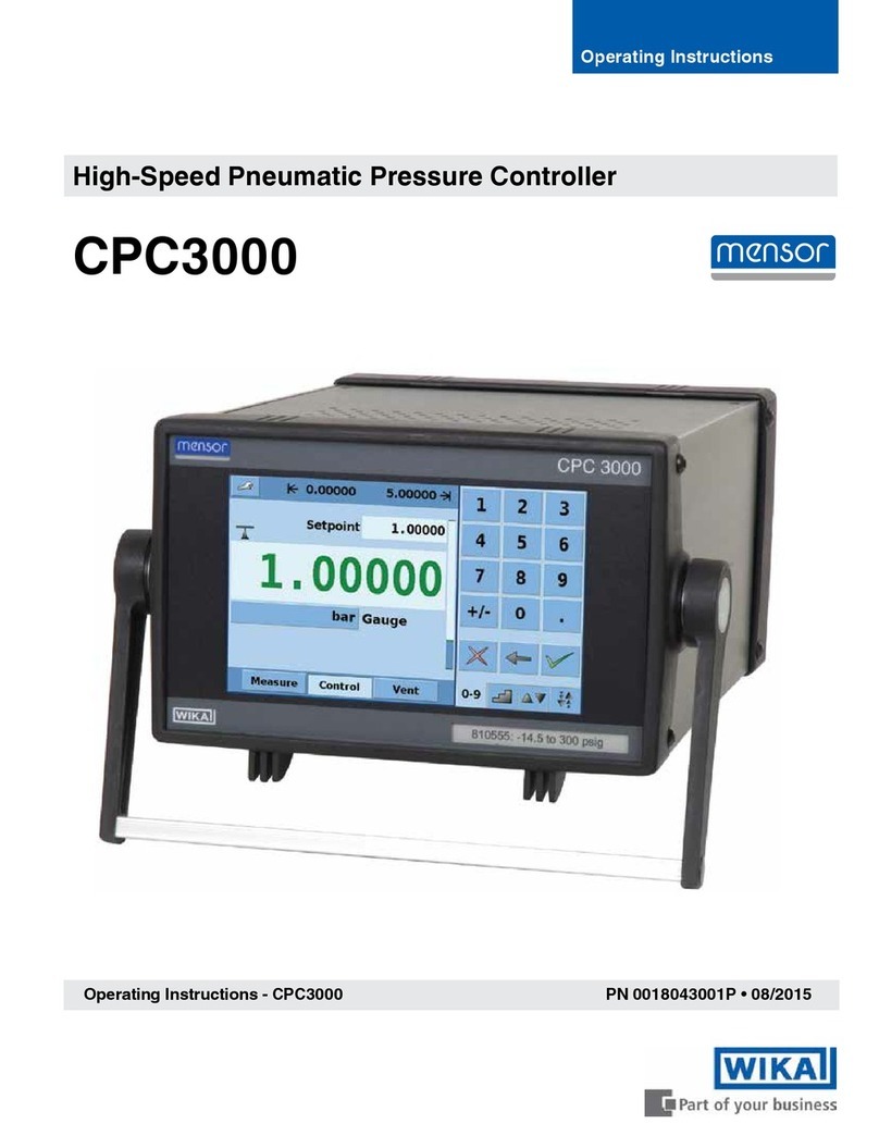
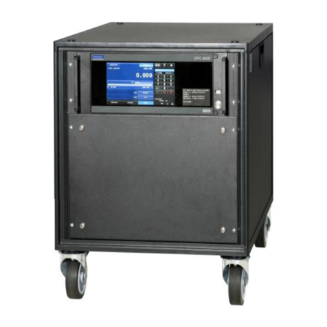
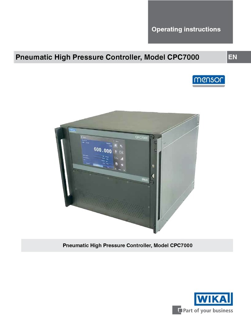
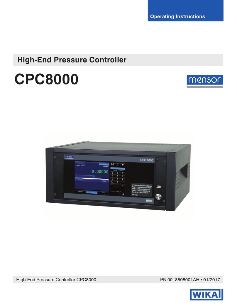
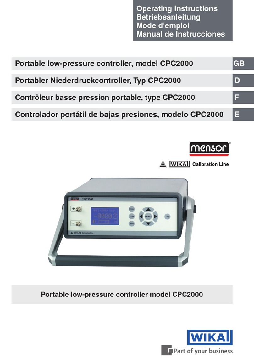
WIKA MENSOR CPC 2000 User manual

CPC 2000
Temporary Operation Instruction
GB
For Low-Pressure Controller CPC 2000

Low- Pressure Controller
CPC 2000
2 WIKA Operation Instruction Low Pressure Controller Version 0.1
Information
This symbol provides you with information, notes and tips.
Warning!
This Symbol warns you against actions that can cause injury to people or
damage to the instrument.

Low- Pressure Controller
CPC 2000
Version 0.1 WIKA Operation Instruction Low Pressure Controller 3
Content
1. General...................................................................................................................... 4
1.1. Safety Instruction................................................................................................... 5
1.2. Specific safety instructions..................................................................................... 6
1.3. Shipping, assembly, electrical connection and startup ........................................... 6
2. Instrument description................................................................................................ 7
2.1. Functional description............................................................................................ 7
2.2. Rear view connections and elements..................................................................... 7
2.3. Power Supply......................................................................................................... 7
2.4. Front view connections and elements.................................................................... 8
2.5. Pressure ports ....................................................................................................... 8
2.6. Button ON/OFF...................................................................................................... 8
2.7. Button MENU......................................................................................................... 8
2.8. The Menu............................................................................................................... 9
2.8.1. Range.................................................................................................................... 9
2.8.2. Unit........................................................................................................................ 9
2.8.3. Steps ..................................................................................................................... 9
2.8.4. Operation Mode..................................................................................................... 9
2.8.5. Language............................................................................................................... 9
2.8.6. Settings.................................................................................................................. 9
2.9. Button LEAK.........................................................................................................10
2.10. Button ZERO ........................................................................................................10
2.11. Overpressure protection........................................................................................10
3. Operation and operation mode .................................................................................11
3.1. Control (CTRL)......................................................................................................11
3.2. Measure (MEAS) ..................................................................................................12
3.3. Automatic (AUTO).................................................................................................13
3.4. Leakage (LEAK)....................................................................................................14
4. Digital interface.........................................................................................................15
4.1. USB......................................................................................................................15
4.2. RS-232 .................................................................................................................15
4.3. Interface configuration...........................................................................................15
4.4. Commands for the serial interface ........................................................................15
4.5. Drivers..................................................................................................................17
5. Troubleshooting........................................................................................................18
5.1. Troubleshooting measures....................................................................................18
6. Re-calibrating and servicing......................................................................................19
7. Dismantling of the system.........................................................................................20
8. Transport of the system............................................................................................20
9. Storage of the system...............................................................................................21
10. Placing out of service................................................................................................21
11. Specifications ...........................................................................................................22
11.1. Dimensions in mm ................................................................................................23
12. Accessories..............................................................................................................24
13. Notes........................................................................................................................25

Low- Pressure Controller
CPC 2000
4 WIKA Operation Instruction Low Pressure Controller Version 0.1
1. General
In the following chapters detailed information on the Low-Pressure Controller CPC2000 and
its proper use can be found.
Should you require further information, or should there be problems which are not dealt
within detail in the operating instructions, please contact the following address:
WIKA Alexander Wiegand SE & Co. KG
Alexander Wiegand Strasse
D-63911 Klingenberg
Fon. +49 - (0) 93 72 / 132-9986
Fax. +49 - (0) 93 72 / 132-217
E- Mail: testequip@wika.de
Factory calibration of the instrument is according to relevant international standards.
The warranty period for the Low-Pressure Controller CPC2000 is 24 months according to the
general terms of supply of ZVEI.
The warranty period is void if the appliance is put to improper use or if the operating
instructions are not observed or if an attempt is made to open the appliance. We also point
out that the content of these operating instructions neither forms part of an earlier or existing
agreement, assurance or legal relationship nor is meant to change these.
All obligations of WIKA Alexander Wiegand SE & Co. KG result from the respective sales
contract and the general business terms of WIKA Alexander Wiegand SE & Co. KG.
WIKA is a registered trade mark of WIKA Alexander Wiegand SE & Co. KG. Names of
companies or products mentioned in this handbook are registered trade marks of the
manufacturer.
We reserve the right to effect reasonable changes on the basis of technical improvements.
Any reproduction of this manual or parts thereof by any means is prohibited.
Version key regarding firmware and respective manual.
Manual
Firmware
0.1
2.5
© 2006 Copyright WIKA Alexander Wiegand SE & Co. KG

Low- Pressure Controller
CPC 2000
Version 0.1 WIKA Operation Instruction Low Pressure Controller 5
This instruction manual describes the features of the Low-Pressure Controller CPC2000 and
provides guidelines for its use. Improper use of this instrument or failure to follow these
instructions may cause injury or equipment damage. All individuals responsible for operating
this instrument must therefore be properly trained and aware of the hazards, and must
carefully follow these operating instructions and the safety precautions detailed within.
Contact the manufacturer if you do not understand parts of this instruction manual.
Handle this manual with care:
It must be readily available throughout the lifecycle of the instrument.
It must be provided to any individuals who assume responsibility for operating the instrument
at a later date.
It must include any supplementary materials provided by the manufacturer.
Conformity
This instrument corresponds to the state of the art and meets all legal requirements set forth
in EC directives as evidenced by the CE label.
1.1. Safety Instruction
This device has been designed and tested in accordance with the
relevant safety regulations for electronic devices. However, its trouble-
free operation and reliability cannot be guaranteed unless the standard
safety measures and special safety advice given in this manual is
followed when using the device.
1. The system must only be operated by trained and authorized personnel who know
the manual and can work according to them!
2. Trouble-free operation and reliability of the device can only be guaranteed so long as
the device is not subjected to any climatic conditions other than those stated under
―11 Specifications‖.
3. The CPC2000 always has to be handled with the care required for an electronic
precision instrument (protect from humidity, impacts, strong magnetic fields, static
electricity and extreme temperatures, do not insert any objects into the instrument
and its openings). The device and sensors must be handled with care (don‗t throw,
hit, etc.). Protect plugs and sockets from contamination.
4. If the device is moved from a cold to a warm environment, condensation may cause
the equipment to fail. You should therefore ensure the device temperature has
adjusted to the ambient temperature before trying to switch it on.
5. If the instrument is to be connected to other devices (e.g. via serial interface) care
must be taken when designing the equipment connections. It is possible that internal
wiring within the external device (e.g. connection of GND to earth) may cause
excessive voltages which could harm or destroy the instrument or other connected
devices.
6. The mains plug of the CPC2000 must always be accessible when connected to a
power outlet, i.e., you must be able to pull the plug from the power outlet without
difficulty, at any time.
If the device is operated with a faulty mains power supply (e.g. short
circuit from mains voltage to output voltage) this could result in
dangerous voltages at the device (e.g. at the sensor socket or serial
interface)!
7. Significant electromagnetic radiation can adversely affect the measuring signal of the
CPC2000 or even disrupt the display of the signal completely.

Low- Pressure Controller
CPC 2000
6 WIKA Operation Instruction Low Pressure Controller Version 0.1
8. The display window behind the plastic film is made of glass (which can splinter). If
there is a possibility that this glass incl. the plastic film might break during operation,
anyone in the close vicinity of the equipment must wear eye protectors, both before
and during operation.
9. Test and calibration assemblies must always be constructed and also dismantled in
an unpressurised state (atmosphere).
10. If the CPC2000 comes in contact with oil (which is forbidden), then subsequent use
with fuels or gases is strictly prohibited, since this could cause an explosion and risks
harm to both people and machinery.
11. If the equipment is damaged and might no longer operate safely, then it should be
taken out of use and securely marked in such a way so that it is not used again.
Operator safety may be at risk if:
There is visible damage to the device.
The device is not working as specified.
The device has been stored under unsuitable conditions for an extended period of
time.
If there is any doubt, please return the device to the manufacturer for repair or maintenance.
12. Customers must not attempt to alter or repair the device themselves. Please return
the device to the manufacturer for any repair or maintenance.
13. Any operation not included in the following instructions or outside the specifications
must not be attempted.
1.2. Specific safety instructions
The Low-Pressure Controller CPC2000 is used for testing and calibrating pressure sensors.
Always observe the operating requirements —particularly the permissible supply voltage—
indicated on the product label and in the ―11 Specifications‖ section of this manual. The
instrument may only be handled as indicated in this manual. The manufacturer is not liable
for damages caused by improper use or failure to follow these instructions. Violations of this
type render all warranty claims null and void.
1.3. Shipping, assembly, electrical connection and startup
Do not close the pressure ports when shipping, as changes in barometric pressure
could damage instruments with low measuring ranges.
Only technical personnel who are appropriately trained and authorized by the
operator of the facility may assemble the instrument and set up its electrical
connections.
Pressurized air or breath is not to be used for performance tests, as this could
damage instruments with low measurement ranges.
Measurement errors may occur if the instrument is not kept protected from sunlight.
Specific safety precautions are given in the individual sections of this manual.

Low- Pressure Controller
CPC 2000
Version 0.1 WIKA Operation Instruction Low Pressure Controller 7
2. Instrument description
2.1. Functional description
The CPC2000 microprocessor-controlled Low-Pressure Controller can be used for the
following:
Easy generating of positive and negative reference pressures
Measuring positive and negative pressures
Measuring differential pressure
Identifying leaks in a test assembly
2.2. Rear view connections and elements
2.3. Power Supply
The Low-Pressure Controller CPC2000 is designed at the factory to
accommodate a supply voltage of 24VDC.
The supply voltage connector is located on the rear of the instrument.
WARNING! Electric shock hazard! Failure to unplug the power supply cord before
replacing the fuse may result in fatal injuries!
USB
RS-232
AC adapter connector

Low- Pressure Controller
CPC 2000
8 WIKA Operation Instruction Low Pressure Controller Version 0.1
2.4. Front view connections and elements
2.5. Pressure ports
Differential pressure instruments will be connected to the + and –pressure ports
Gauge pressure instruments will be connected to the + pressure port (- port is open to
the atmosphere)
Negative gauge pressure instruments will be connected to the –pressure port (+ port
is open to the atmosphere)
2.6. Button ON/OFF
Button to turn the instrument ON or OFF
2.7. Button MENU
Via this key, the customer gets into the Setup- Menu and is able to do various
adjustments to the different operation modes. After using the MENU button in the
control mode the controller is in vent mode.
Pressing the SETUP button allows the operator to
adjust the following 6 settings. A detailed description to
the menu items can be found in section: ―2.8 The
Menu‖
RANGE: Set the control pressure range (End
value)
UNIT: Choosing the pressure unit (Pa, kPa,
hPa, bar, mbar, psi, inH2O, inHg, mmHg, Torr)
STEPS: Alignment of the step size in %. Within the range 0 … 50% adjustable.
MODE: Choosing the operation mode
oCONTROL (CTRL): Controls a setpoint
oMEASURE (MEAS): Measuring of differential and gauge pressure
oAUTOMATIC (AUTO): drives through a programmed sequence
LANGUAGE: Choosing the language
SETTINGS: Further settings to the controller can be done in this menu item.
+
Pressure
connector
-
Main switch
Navigation keys

Low- Pressure Controller
CPC 2000
Version 0.1 WIKA Operation Instruction Low Pressure Controller 9
2.8. The Menu
Press the button MENU and use the keys UP / DOWN to get to the right menu item. You get
into the sub menu via the key SELECT. The following sub menu items are available.
2.8.1. Range
It is possible to change the controller end value of the sensor range to protect device under
test with smaller pressure ranges.
2.8.2. Unit
This feature allows the operator to select the units used for displaying pressures. Certain
measurement ranges cannot be displayed meaningfully in some units, in which case the
units in question are not available. The following units may be selected:
Pa, kPa, hPa
bar, mbar
psi, inH2O, inHg, mmHg
Torr
2.8.3. Steps
This feature allows the user to modify the percentage of the set value. The value is free
adjustable within the range 0 … 50 %.
2.8.4. Operation Mode
This feature allows the user to modify the general operation mode of the controller.
The following modes are available:
MEASURE (MEAS): The controller measures the pressure in the selected pressure unit
CONTROL (CTRL): The controller regulates to a set point.
AUTOMATIC (AUTO): Runs through a programmed sequence.
2.8.5. Language
This feature allows the operator to select either German or English as the language used.
2.8.6. Settings
Zeroing: Turning the automatic zeroing after
quitting the menu on or off. The customer is
also able to the set a frequency in which the
sensor automatically performs a zero-point
adjustment.
RS232 / USB: Choosing the actual interface
Display: Brightness adjustment
Auto: Setting the pressure range, unit and
pressure steps for the automatic mode. Steps
Up and Steps Down can be assigned different
Navigation in the MENU:
SELECT: Serves to confirm/ select the respective settings
Left/ right: Select the digit
Up/Down: Switch between the different menu items.

Low- Pressure Controller
CPC 2000
10 WIKA Operation Instruction Low Pressure Controller Version 0.1
step size.
Info: Basic information about the instrument and manufacturer.
2.9. Button LEAK
The test feature blocks both pressure ports, allowing the operator to measure a
drop in pressure on the test object itself. (This feature is only in the control mode
available)
2.10. Button ZERO
Button for manual zero adjustment of the integrated sensor.
By external influences such as temperature, location, or ambient pressure the zero
point of the device can move. During the zero-point adjustment, the unit
automatically determines this shift, and expects them into the displayed pressure.
The zero adjustment requires a switch of the internal valves, which is not possible without a
pressure drop. If this interferes with the use case of the automatic zero point adjustment can
be switched off.
2.11. Overpressure protection
It is not allowed to override the permissible overpressure safety: CPC2000-1mbar /
CPC2000-10mbar / CPC2000-100mbar have a 5 time overpressure safety; CPC2000-
1000mbar has a 2 time overpressure safety.

Low- Pressure Controller
CPC 2000
Version 0.1 WIKA Operation Instruction Low Pressure Controller 11
To change set value by x%:
Pressure change in % via / - key
Pressure change to 100% via - key
Pressure change back to 0% via -key
3. Operation and operation mode
3.1. Control (CTRL)
The control mode is used to calibrate pressure transducers, switches or other pressure
instruments. In CTRL- Mode the pump is active and regulates the set point. The internal
sensor provides the corresponding measuring value over the display.
Settings:
Press the MENU button. Verify the menu item MODE with SELECT and switch
between the MODE options until CTRL is shown in the display. Accept with SELECT.
Change the end value of the control range in the menu item RANGE. Accept with
SELECT.
Choosing a pressure unit in the menu item UNIT and accept with SELECT.
Quit the menu with the key MENU
Utilization:
After quitting the menu the controller is in vent
mode, which means the controller is vented to
atmospheric pressure. The maximum control
pressure is displayed in the upper middle of the
display. The percent value can be read in the
lower middle of the display. You can switch
between the pressure set point and percent
value via the SELECT button.
The percent value can be changed via the UP / DOWN (in the defined steps) and
LEFT / RIGHT button.
The target pressure set point can be changed only with the keys UP / DOWN. With
LEFT / RIGHT can be jumped to the appropriate place of the target digit.
As soon as the display of the Controller indicates a stable value, the data can be noted:
Set point in % of Span
Current measuring value
Unit
End Value / Span
Battery status
Operation mode
Current set point in unit

Low- Pressure Controller
CPC 2000
12 WIKA Operation Instruction Low Pressure Controller Version 0.1
In CTRL- Mode it is possible to do a manual zero point adjustment to the controller and
check connected devices for leaks.
Manuel zero point adjustment: Press ZERO and the reference sensor in the
instrument will be synchronized.
Leak Test: By pressing the LEAK button, the control process will be stopped and the
system will be closed. By pressing the LEAK button again the controller leaves this
mode and the control mode will be activated.
3.2. Measure (MEAS)
The MEAS- mode is used to measure gauge or differential pressure. The pump is not active
during measuring. The pressure is captured by the internal sensor.
Settings:
Press the MENU button. Verify the menu item MODE with SELECT and switch
between the MODE options until MEAS is shown in the display. Accept with SELECT.
Menu items RANGE and STEPS are not needed for the MEAS- Mode
Choosing a pressure unit in the menu item UNIT and accept with SELECT.
Quit the menu with the key MENU.
Sub menu item Settings:
oGo to the menu item Settings via the UP / DOWN buttons and accept with
SELECT:
oGo to the sub item zeroing and accept with SELECT.
oUnder the sub item Auto –Zero you can turn the auto-zero point adjustment
during measuring on or off.
Utilization:
Depending on the settings the controller does a zero point adjustment after quitting the
menu. Afterwards the controller starts measuring the pressure.
Zero Point adjustment can be done any time manually by pressing the Zero button.
Crosses the measured pressure the maximum permissible load (125%) the
internal sensor will be blocked by a solenoid valve. Error is indicated in the
display. You can unlock and de- allocate the instrument with SELECT key
Current measuring value
Battery status
Operation mode
End Value / Span
Unit
Deviation in pressure unit

Low- Pressure Controller
CPC 2000
Version 0.1 WIKA Operation Instruction Low Pressure Controller 13
3.3. Automatic (AUTO)
In Automatic- mode a pressure sequence can be programmed. This is useful if several
pressure transducers or pressure switched will be calibrated with the same pressure values.
Additionally the mode makes it possible to drive off a fixed profile several times successively.
Settings
Press the MENU button. Verify the menu item MODE with SELECT and switch
between the MODE options until AUTO is shown in the display. Accept with SELECT.
The submenu items Range, Unit and Steps are not relevant for the Automatic- Mode.
Go to the menu item Settings via the UP / DOWN buttons and accept with SELECT.
The item Auto- Zero is not relevant.
Go to the item Automatic- Mode via the UP /
DOWN buttons and accept with SELECT.
oRANGE: Sets the max control range
(End value)
oUNIT: Sets the pressure unit
oSTEPS: Number of upward and
downward cycle steps. The step size
will be calculated trough the controller.
In the submenu item CONFIGURATION 1 you can specify further attitudes for AUTO- Mode.
Cycles: Here you specify the number of cycles, which are to be driven off in the
AUTO mode.
T Start: Waiting period until venting the
instrument.
T Stop: Waiting period after reaching the
specified pressure
T Hold: Hold Time until controlling to a new set
point.
T Pause: Waiting period between two cycles
Auto Zero: Auto Zero adjustment after each
cycle.
Press MENU to leave submenu.
Utilization
After leaving the menu the controller is on hold. All information for the automatic mode are
shown at the display.
Current Phase:
Phase 1: Venting the
system
Operation mode
Span
Unit
Current pressure value in percent of
span
Current Cycle

Low- Pressure Controller
CPC 2000
14 WIKA Operation Instruction Low Pressure Controller Version 0.1
The illustration shows the flow chart for the AUTO mode. According to the following table you
can recognize which cycle gone through and the respective meaning.
Stage
Meaning
1
Waiting fort he start command via SELECT key
2
Waiting period which can be set in the Configuration
4
Time for Zero- Point Adjustment
7
Hold time at the zero point
9
Time to control to the set point
10
Hold Time
13
Hold time at the maximum pressure
15
Time to control to the set point
16
Hold time at the zero point
18
Break time which can be set in the Configuration
Between phase 10 and 16 the data of the controller can be noted and evaluated if the value
is stable. You can leave the AUTO mode with the MENU key. Vent will indicated in the upper
left of the display.
3.4. Leakage (LEAK)
Connected device under test can be tested of leaks in CTRL- Mode.
Settings
To check a device under test for leaks the instrument has to be in CTRL- Mode.
Enter the desired pressure via UP / DOWN or LEFT / RIGHT keys.
As soon as the pressure is stable press the LEAK button. The internal Pump is
switched off and the pressure stays in the system
Utilization
Current measuring value
Leakage
measuring time
Operation mode
Start value
Unit
Deviation in pressure unit
Deviation in %

Low- Pressure Controller
CPC 2000
Version 0.1 WIKA Operation Instruction Low Pressure Controller 15
4. Digital interface
You have the possibility to adjust or observe the controller with a PC over digital interface
(USB or RS-232). In control, measure and automatic mode it is possible to release the
current instrument status switching on or off as a cycle. Release cycle is 1 second.
4.1. USB
The USB interface makes a virtual ComPort available to the PC. The instrument control is
not different then controlling a RS-232 interface.
4.2. RS-232
RxD, TxD and GND cable will be required for connection. The connection is carried out with
a straight RS-232 cable. (male to female)
4.3. Interface configuration
Press the MENU button to get into the main menu. Use the buttons UP / DOWN until you get
to the item Settings and accept with SELECT. Go to the submenu item RS232 / USB via the
keys UP / DOWN and accept with SELECT. The following settings can be adjusted:
Active: Choice of used digital interface and activate the interface communication
(USB, RS-232)
Baud: Choosing the baud rate (1200, 2400, 4800, 9600, 14400, 19200, 28800,
38400, 56000, 57600)
Data- Bits: fixed value (8)
Stop- Bits: fixed value (1)
Parity- Bits: fixed value (N)
4.4. Commands for the serial interface
All interface commands are introduced with a colon and locked with carriage return (CR).
Commands and parameters are to be separated by a blank. By adding a question mark to
the command the corresponding parameter can be read out. Received commands are
acknowledged with „SELECT ―, not existing or wrong instructions with „ERROR ―.
Command
Function / Response
:saaz <0 | 1>
Auto Zero before each cycle (Phase 4)
0 –Off
1 - On
:acy <1…100>
Number of cylces
1…100

Low- Pressure Controller
CPC 2000
16 WIKA Operation Instruction Low Pressure Controller Version 0.1
:asd <1...100>
Steps Down
1…100
:asu <1…100>
Steps Up
1…100
:ate <0…10000>
Waiting period at the end value (Phase 13)
1…10000 --> Time in seconds
:ath <1…10000>
Hold time (Phase 10 and 16)
1…10000 --> Time in seconds
:atp <1…10000>
Break time (Phase 18)
1…10000 --> Time in seconds
:atr <1…10000>
Tolerance band
1…10000 --> Tolerance in 0,01% Fullscale.
Hold time starts counting when controll over 1 second in this
tolerance band.
:ats <1…10000>
Start delay time (Phase 2)
1…10000 --> Time in seconds
:o <0 | 1>
Output status information via interface
0 --> Off
1 --> On
:pa <-110…110>
Increase desired pressure by x percent
-110…110 --> Change set point in %
:pd
Decrease current pressure value in % (Step DOWN).
:pr <-1100…11000>
Adjustment of active measunring/ control range -
1100…11000 --> new range in 0,01% FS
:ps <-10…110>
Set pressure in percent
-10…110 --> Desired pressure in %
:pu
Increase current pressure value in % (Step UP).
:saz<0 | 1>
Set Auto Zero (in Measure or Control Mode)
0 --> Off
1 --> ON
:sbr<0…1>
Set Baudrate RS232
0 --> 1200
1 --> 2400
2 --> 4800
3 --> 9600
4 --> 14400
5 --> 19200
6 --> 28800
7 --> 38400
8 --> 56000
9 --> 57600
:sbu<0…1>
Set Baudrate USB
0 --> 1200
1 --> 2400
2 --> 4800
3 --> 9600
4 --> 14400
5 --> 19200
6 --> 28800
7 --> 38400
8 --> 56000
9 --> 57600

Low- Pressure Controller
CPC 2000
Version 0.1 WIKA Operation Instruction Low Pressure Controller 17
:sci<n | u | r>
Set active Interface
n --> digital interface off
u --> USB aktiv
r --> RS232 aktiv
sdb <0…100>
Display brightness
0…100 --> Brightness in %
:spu <0…9>
Pressure Unit
0 --> Pa
1 --> hPa
2 --> ka
3 --> mbar
4 --> bar
5 --> Torr
6 --> mmHg
7 --> inHg
8 --> psi
9 --> mmH2O
10 --> inH2O
:ssl <d | e>
System language
d = German
e = English
:ssw <1…100>
Step size
1…100 --> Steps size of the buttons UP /DOWN in manual
mode in %
:swm <a , c , m , z , l , v , s>
Set operation mode of the controller
a --> Start Automatic Mode
c --> Start Control Mode
m --> Start Measure Mode
(Only in Control or Measure Mode available)
z --> ZERO
(only in Control Mode available)
l --> LEAK- Test
l --> back to Control Mode (Like LEAK button)
v --> VENT (Vents the whole system)
(Only in Automatic Mode available)
:szc <0,1>
Auto Zero Adjustment before entering Control Mode
0 Off
1 On
:szi <1…60>
Auto Zero adjustment period
1…60 --> Zeit in Minuten
4.5. Drivers
Current interface driver will be available for download on Future Technology Devices
International Limited (FTDI) homepage for all established OS (Windows, Linux, Mac Os).
Homepage URL: http://www.ftdichip.com
Download URL: http://www.ftdichip.com/Drivers/VCP.htm (FTDI Homepage -->
Drivers --> VCPDrivers)

Low- Pressure Controller
CPC 2000
18 WIKA Operation Instruction Low Pressure Controller Version 0.1
Installation guide for each OS: URL:
http://www.ftdichip.com/Documents/InstallGuides.htm (FTDI Homepage -->
Documents --> Installation Guide)
5. Troubleshooting
The individual responsible for the electrical connections must be notified
immediately if the instrument is damaged or if errors occur that cannot be
corrected as indicated in section 5.1.
This individual must take the instrument out of service until the error has
been corrected and ensure that it cannot be used unintentionally.
Only the manufacturer may perform repairs that require the housing to
be opened.
Always unplug the power cord before opening the instrument!
If faults cannot be repaired, the system must be put out of operation
immediately and this information is to be given to the manufacturer.
Repairs must only be carried out by the manufacturer. Interventions and
changes on the appliance are not allowed.
In case of faults caused by defects of the electrical or pneumatic/hydraulic equipment the
operators must inform their superiors immediately and call in the qualified and authorised
technical staff for maintenance.
5.1. Troubleshooting measures
Problem
Cause
Correction Action
Instrument does not work,
Display does not light up
No power
Check to see if the
electrical cord is plugged
in properly
Battery is empty and has
to bee recharged
Instrument does not reach
set pressure; pump runs
continuously
Leaks in system, Tubing
diameter too large
Secure tubing properly;
eliminate any leaks
Maximum tubing
diameter 5 mm
Further help can be found through WIKA‗s Test & Calibration Technology Department.

Low- Pressure Controller
CPC 2000
Version 0.1 WIKA Operation Instruction Low Pressure Controller 19
6. Re-calibrating and servicing
We recommend having the system re-calibrated by the manufacturer at regular intervals of
approx. 12 months. Every re-calibration at the factory also includes a comprehensive and
free checking of all system parameters. During the first re-calibration a service file is started
automatically in which every re-calibration and all extra services are recorded.
The instrument requires almost no maintenance, because all parts which are moveable are
extremely robust. There are no parts which have to be serviced by the user. During each re-
calibration the functioning of all components is checked and changed if necessary.
To clean the membrane keypad and the display, use only customary plastic or glass cleaning
agents in compliance with the guidelines of the manufacturer. Use cloths which are not prone
to generate fluffs.
Before cleaning the surface of the instrument, it has to be made sure that
it is not pressurized, the power is switched off and the power supply is
disconnected.

Low- Pressure Controller
CPC 2000
20 WIKA Operation Instruction Low Pressure Controller Version 0.1
7. Dismantling of the system
Work on electrical or pneumatic/hydraulic equipment must only be
carried out by qualified and authorized technical staff, observing the
corresponding safety regulations.
When dismantling the system please proceed as follows:
1. Make sure that there is no positive or negative overpressure on the system and that
all parts of the appliance are at room temperature.
2. Switch off the system from the main switch ON/OFF at the front.
3. First pull out the mains cable from the mains socket and then from the power supply
input socket of the system.
4. Disconnect the pressure connections.
5. Make sure that the system is free of any medium.
8. Transport of the system
Before the system is shipped all remains of any medium stuck to it must
be removed. This is particularly important if the medium is a health
hazard such as a corrosive, toxic, carcinogenic, radioactive, etc.
Before returning any equipment, please fill out the appropriate Goods-Return Form, found on
the WIKA Web site (www.wika.de see: Service / Product return), and a reference number will
be issued to you. Then send the instrument with this reference number attached to the
delivery address indicated.
Please follow the following instructions to prevent damage.
1. Wrap the system in antistatic plastic foil.
2. Using the insulating material, place the system in the box in such a way that there is
about the same amount of insulating material on all sides of the transport box.
3. If possible, add a bag of desiccant to the box
4. Make sure that the shipment is marked as transport of a highly sensitive measuring
instrument.
Other manuals for MENSOR CPC 2000
1
Table of contents
Other WIKA Controllers manuals
Popular Controllers manuals by other brands

Hydrofarm
Hydrofarm Autopilot APCTART instruction manual

Xilica Audio Design
Xilica Audio Design NEUPANEL MINI Product installation guide

Amphenol
Amphenol Telect nrgSMART Controller Configuration user guide

ELREHA
ELREHA EVP 3260 Technical manual

Allen-Bradley
Allen-Bradley PowerFlex AFE Hardware Service Manual

Linak
Linak TD4 user manual