Norden NVS-DC600013CH User manual

NVS-DC600013CH
Intelligent Conference Controller
User Manual
1
The Installation and Operation Manual of the series intelligent digital conference
system includes detailed description with respect to installation and operation of all
equipment of the conference system of such series. This Manual mainly includes description
of the functions and ports of all equipment units in the series conference system, graphic
illustration of connection between equipment, description of system configuration and
operation instructions as well as precautions and technical indexes. Please read this Manual
carefully before disassembly of the equipment and preparation for installation, in order to
install and operate the equipment properly. Please keep this Manual in good custody for
future reference. For other information or parameters with respect to the equipment
uncovered in this Manual, please contact the local dealer or after-sales service personnel of
our Company.
About this User Manual
This User Manual is available and effective upon completion of
development of the Series intelligent digital conference system. The User Manual
includes system description, matters needing attentions in use, instructions on
system connection, instructions on use of product and technical specifications of
the Series intelligent digital conference system. Please read this User Manual
carefully before connection, installation and use and operate in accordance with
corresponding instructions in the Manual.
This symbol on the rear panel indicates matters needing attentions, please
use or operate the production accordance with corresponding instructions.
Please keep this User Manual in good custody for future use.

2
INDEX
System Overview
Introduction………………………………………………………………………………………………………………………………….4
Technical Features………………………………………………………………………………………………………………………..4
Functional Features………………………………………………………………………………………………………………………7
Conference Host
General Introduction…………………………………………………………………………………………………………………..10
Connections
Connection between conference host and conference units……………………………………………………….20
Connection of cameras……………………………………………………………………………………………………………….24
Connection of alarm and line in and line out………………………………………………………………………………26
Control system and network connection…………………………………………………………………………………….27
Connection between hosts and extended controllers…………………………………………………………………28
Connection of conference units to extended controllers…………………………………………………………….29
Operations
Power on the equipment……………………………………………………………………………………………………………30
Music Playback…………………………………………………………………………………………………………………………..30
Number of speech units……………………………………………………………………………………………………………..31
Camera tracking…………………………………………………………………………………………………………………………32
Camera Selection……………………………………………………………………………………………………………………….33
Conference mode………………………………………………………………………………………………………………………34
Sound control…………………………………………………………………………………………………………………………….36
Recorder…………………………………………………………………………………………………………………………………...38
System Settings
Network Setting………………………………………………………………………………………………………………………..39
Camera Tracking and Positioning………………………………………………………………………………………………40
Unit Testing………………………………………………………………………………………………………………………………43
Unit Settings…………………………………………………………………………………………………………………………….46
Speaking time setting……………………………………………………………………………………………………………….49

3
Chime Settings…………………………………………………………………………………………………………………………….50
System time settings……………………………………………………………………………………………………………………51
Display settings……………………………………………………………………………………………………………………………51
General Settings………………………………………………………………………………………………………………………….53
Configuration of Address Coding on Extended Host…………………………………………………………………….55
Fuse Installation on the Host……………………………………………………………………………………………………….56
Conference Units
General Introduction…………………………………………………………………………………………………………………..58
Connections
Connection of conference units to hosts……………………………………………………………………………………..76
Headphone connection……………………………………………………………………………………………………………….79
Operations
Numbering of conference units…………………………………………………………………………………………………..80
Speech………………………………………………………………………………………………………………………………………..82
Voting…………………………………………………………………………………………………………………………………………88
Unit Testing………………………………………………………………………………………………………………………………..89
View microphone status (for conference unit with screens)……………………………………………………….92
Language settings (for conference unit with screens)…………………………………………………………………93
System Connections
Introduction………………………………………………………………………………………………………………………………94
Connection Diagram of the Conference Host and Units……………………………………………………………..95
4
NVS-DC600013CH
NVS-DC600083CE

5
System Overview
Introduction
The series Digital Conference System is based on ARM9 Embedded System Platform
and adopts high performance DSP technologies and Hi-Fi circuit design, which integrates the
advanced control technologies and audio processing technologies effectively, to realize a
comprehensive solution with digital control, high-level audio transmission and visualized
operation. The system can easily realize conference recording throughout the whole process
and can be connected to PCs to realize remote conference control and it supports wireless
control via an Android tablet PC. The series intelligent digital conference system provides
functions such as discussion speech, votes, conference check-in, simultaneous interpretation,
infrared voice distribution, teleconference, and automatic camera tracking, etc. The system
is composed of hosts, conference units, cameras, and corresponding application software.
The conference system includes conference hosts and extended hosts. The conference units
include chairman speech units, delegate speech units, vote units, interpretation units and
infrared voice receiving units, etc. Application software includes computer remote control
software, Android tablet PC control software and other application software. The conference
units in the system are connected to one another by "+ shape" adapters in a series with 8-
core cables, which is simply for installation and engineering, safe and reliable and has good
anti-jamming capability.
Technical Features
1. Built-in high performance ARM processor
The system adopts embedded operating system, which is stable and reliable and
supports TCP/IP connection and voice recording functions, etc.
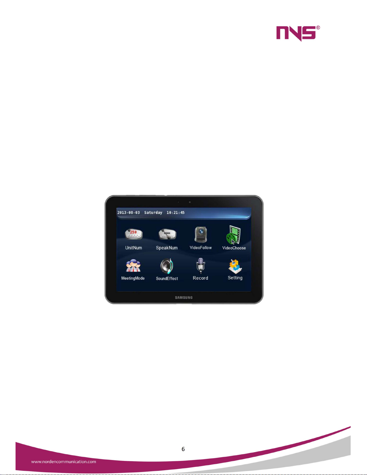
2. 4.3" high-definition colour touch screen
All functions and settings operations process are displayed via a GUI, with which the
functions are clear, and the touch operations are visualized and simply. The human-machine
interaction is user-friendly.
Main interface of the Host
6
3. TCP/IP network interface
The system integrates modern network technologies and realizes network connection
to PC via the Ethernet, so the remote-control software independently developed by our
company can be used to control all functions of the conference system, such as voting, check-
in and system setting, etc.
4. Mobile control terminals
The system integrates WIFI technologies, so the Android system platform can be used
to control all functions of the conference system, via Android and 3G (wired or wireless
connection) tablet PC. (In case WIFI is used, such tablet PC only needs to be in a same network
with the conference system, while if 3G technology is used, remote control may be used by
professional network engineers.)
Control panel of the tablet PC
5. Built-in high performance DSP technology
It adopts high performance DSP technology with 14-band graphic equalizer, frequency
shifter, low cut, and other feedback inhibition functions. The equalizer can save six settings in
manual mode and the system also provides a variety of default modes, so that it ensures that
the system can output Hi-fi audio signals.

7
Equalizer settings interface of the Host
6. Automatic Camera Tracking System
The system can connect 6 BNC cameras, and switch among 6 HDMI with the automatic
camera tracking function. The angle and the swing speed are both adjustable and their values
will be stored. The system supports cameras compatible with PELCO D/PELCO P/VISCA
protocols. If all 6 interfaces are used at a same time, they must be connected to cameras of
the same model.
7. Conference System Host
The conference system host is the core equipment of the whole conference system,
and it provides electric power supply to the conference units connected to it. It is a platform
integrating ARM, DSP, and other software with system hardware to realize system control. A
host may be connected to maximally 128 conference units and with extended hosts (a system
allows a maximum number of 31 extended hosts) the system can be connected to up to 4096
conference units, in which any number of chairman speech units may be connected to the
system and two of them may be designated as control units. The conference host can realize
conference control, unit configuration, electronic voting, camera tracking and audio
input/output, and can be connected seamlessly to the central control system. When the
system host is connected via Ethernet to PC where remote control software is installed, it can
realize remote conference control.
8. Conference Unit
The conference unit is the basic equipment for delegate to attend and operate the
conference. Conference units include chairman units, delegate units, interpreter units and
speech units, etc. And such conference unit for each conventioneer may vary from person to
person, for instance, the chairman may use a chairman unit with speech key which has
absolute control and operation rights for the order of the conference. The conference units
are uniformly powered by the host where there are interfaces for speakers and headphones.
Conference units integrated with speech and vote functions are equipped with a LCD screen
and a LED indicator, while those conference units only for use in speech or votes are only with
LED indicators.

8
Functional Features
1. Discussion speech
Limitations on the number of simultaneous speakers (1/2/3/4/5/6), and speech
timing and countdown function.
2 chairman units can be set in 1 system.
VIP delegate units with speech keys can be set.
In the system software, a delegate unit with speech key may be set as a VIP unit, which
works under the FREE mode, where VIP unit can make free speeches when maximally 20
units (including VIP units and normal units) are activated, while in other modes, the VIP unit
can make speech freely when the total activated units are no more than 10. The system
allows a maximum number of 30 VIP units.
The system provides five speech modes:
a) FIFO mode: Speech is delivered in a first-in-first-out mode. After the
activated delegate units reach the maximum limit, any newly activated
units will deactivate the first activated one.
b) NORMAL mode: Speech will be delivered in queue. After the number of
activated delegate units reaches the maximum limit, all newly activated
units may wait in a queue until a previously activated unit is off.
c) VOICE mode: The conference units are in a voice control mode (VIP units
and chairman units are free). Within the maximum unit limit, the speech
unit will be activated by voice signal received. Both the sensitivity and
length of speech are adjustable.
d) FREE mode: The conference units are in a free mode (chairman unit is free).
Within the limits on activated speech units, the order of speech is free of
any limitation.
e) APPLY mode: The conference units are in a speech application mode (VIP
units and chairman units are free). An individual speech unit sends an
application for speech, and the speech will be delivered after such
application is approved by the chairman unit.

9
2. Voting
The Vote function is only available on the conference units with vote functions. For
units with LCD screen:
The LCD screen on chairman unit and delegate units will display all indication content
for the voting operation, and the chairman and the delegate can complete the voting
operation (Affirmative/Negative/Abstention) on basis of such indication.
The LCD screen will display the total number of votes, affirmative votes, negative votes
and abstention votes.
It can realize various forms of voting can be implemented.
For units without LCD, the voting is initialized on PC application software and the delegate
may vote by pressing the corresponding buttons in accordance with instructions at the
conference venue. The result of votes will be displayed on the PC software.
3. Conference check-in
Conference check-in is initialized by the PC control software, and after the conference
unit enters its check-in mode, the delegate may complete the check-in by pressing
corresponding buttons in according to the indication on such conference unit.
4. Sound control
Sound control includes adjustment to the AUX input volume, control of master volume
(control all input/output volume), low cut, frequency shifter and equalizer.
5. Camera tracking system
The conference system integrates a camera tracking system with 6 BNC camera
interfaces and 6 HDMI camera interfaces, which can realize automatic camera tracking
function.
6. Conference recording
On the main interface, touch the "Recorder" button to enter the recorder operation
interface. The conference system can realize conference recording, and the audio file
recorded may be saved on a USB flash disk. Before the recording is started, plug a USB
flash disk to the front panel of the conference controller, otherwise the recording function
cannot be realized.

10
7. Unit testing
Before the meeting begins, test the microphone, LCD screen, buttons, LED indicator
light and speaker of the meeting unit to see whether the above parts can work normally.
There are two testing methods: automatic testing and manual testing.
8. Speech timing and countdown
With the speech timing function, the speech time for units can be set, or be free when
deactivating this function. The speech time may be set within a range of 1-300 minutes
and the warning countdown at the end of such speech time may be set to be 1-60 seconds.
9. System time adjustment and setting of LCD status
The system time and the time of screen saver can be set.
10. Remote control
The system can be connected to a PC via TCP/IP or to an Android tablet PC via WIFI,
to realize remote control of the conference system and centralized control over several
conference systems.
11. Seamless connection to control system
The intelligent digital conference system can be connected seamlessly to the central
control room, forming a complete conference system solution, to realize comprehensive
management over the multi-media peripheral equipment, lights, projectors, and audio
system at the conference venue. It can integrate, specialize, intelligentise the system to
its largest extent, and simplify the system layout and save resources.
12. Other functions
The system provides audio input/output interfaces and warning signal override
function. It can be connected to players, amplifiers, and fire control centre to realize
emergent fire alarm function.

11
Conference Host
General Introduction
The series conference system includes conference host and extended host. It
integrates the automatic camera tracking function, 4.3" TFT touch screen, simply and clear
GUI display as well as other advanced management and control functions, which will lead the
design trend of conference system equipment. The conference host is the core equipment of
the conference system, which can provide power supply to all conference units and is well-
extensible. The series digital conference host supports check-in, voting, camera tracking,
automatic testing and data management functions. It provides multiple conference modes
for users (FIFO, NORNAL, FREE, VOLCE, APPLY). A host may be connected to maximally 128
conference units and with extended hosts (a system allows a maximum number of 31
extended hosts), the system can be connected to up to 4096 conference units, in which any
number of chairman units with speech keys may be connected to the system and two of them
may be designated as control units. Any unit on the host can be set as the VIP unit. The system
allows automatic or manual testing the MIC, speaker, buttons, LED indicators and screen on
the conference units. The host has built-in digital sound processor (DSP), which can set up
multiple EQ modes and select the corresponding mode according to different conference
situation. With audio input/output interface and alarm signal override function, the host can
expand more broadcast functions; with the limitation on spokesman and speech timing
settings, it can effectively maintain the order at the conference venue; with 6 BNC camera
interfaces and 6 HDMI camera interfaces, it can directly connect the camera to realize
conference video tracking.
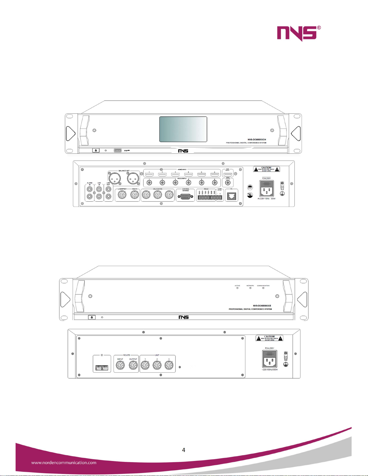
Models of Conference Hosts:
NVS-DC600013CH Intelligent Conference Controller
NVS-DC600083CE Conference System Extension Controller
NVS-DC600013CH Intelligent Conference Controller
Features
Comply with IEC 60914 international standards.
The conference host allows connection of a maximum number of 128 conference
units and with the extended host, 1 conference system allows connection of up to
4096 units.
Connection through 8-core aviation plugs in a series mode.
Limitation on number of spokesman at a same time (1/2/3/4/5/6).
Vote function, timed speech, and other data management functions.
4.3" TFT display/touch screen.

12
The system adopts graphic interface and all functions and configuration messages as
well as basic information of the units are displayed clearly, besides it has artistic and
modern appearance.
Operation via touch screen makes human-machine interaction easier.
Users can adjust the system time and back light duration, to save energy.
Messages on the system LCD screen may be in Chinese or English
Users can set several VIP speech units, which when the total number of activated units
is less than the limit of 20 (20 in FREE mode and 10 in other modes), can be activated
and if free of any limitation of conference mode. A maximum number of 30 VIP units
are allowed.
The system supports five conference modes, namely FIFO, NORMAL, VOICE, FREE and
APPLY.
The system has embedded a DSP, including low cut, frequency shifter and equalizer.
The system can realize recording of the entire conference and provides two recording
modes, namely automatic recording and manual recording, and the user can choose
the desired one.
The system provides unit testing function, with which testing the conference units
may be realized automatically or manually.
It provides speech timing and countdown function. With the speech timing function,
the user can set a time limit for each speech or deactivate this function.
The conference systems also provide a camera tracking system and 4 BNC camera
ports through which the system can realize automatic camera tracking function.
The system provides one RS232 serial port, with which the system can be connected
to the central control system seamlessly, in addition, it also provides one RS422 serial
port for connection of camera control circuit to realize centralized control on the 6
cameras.
The 8-core aviation socket: one is for connection of interpreter host, anther for
connection to extended host and three for conference units.
RCA sockets:
Two secondary audio input ports, for connection to audio players, etc.
Two secondary audio output ports, for connection to specialized amplifiers.
Two warning audio signal input ports for connection to warning audio signals
in the fire control centre.
Cannon socket: It is a secondary audio output port and is used to realize parallel
output together with two secondary audio output RCA sockets (LINE OUT) and for
connection to specialized amplifiers.
The system also provides a +5V trigger voltage warning input port, which, together
with the warning audio input port, is used to realize warning breaking in function.
The system provides RJ45 ports under TCP/IP protocol, which is used for connection
to the network where a PC application program will be used to control all functions of
the system.
The equipment casing is made from metal materials and all the lines and casing are
properly grounded, so the system has an anti-static of 10kV in case of physical contact
and 15kV in case of air contact.

13
The system adopts high-grade appearance design, 2U standard chassis, and can be
installed in a 19-inch standard cabinet.
Front Panel
1. Power switch (POWER)
Power is on when the button is pushed down and is off when the button is ejected.
2. Power indicating light (ON)
The indicating light will be on, when the system is powered on, and it is off when the
system is powered off.
3. USB port (USB)
For connection of USB flash disks during the recording process.
A mouse with USB port may be connected to operate the system.
4. LCD touch screen display
For display of function icons and menus in the operation process; touch screen is used
in configuration.
5. Screw holes for installation in cabinets
14
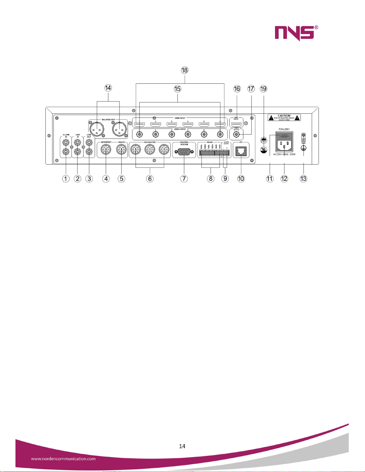
Rear Panel
1. Warning audio signal input port (ALARM IN)
It is used for connection to be warning signals from the fire control centre and is
interlocked to the warning triggering signal as mentioned in
⑨
.
2. Line audio signal input port (LINE IN)
It is for connection of sound source or sound console equipment to provide line
audio signal to this system.
3. Mix output of audio signal (LINE OUT)
It is for connection of amplifiers, and the output signal includes line audio signals,
warning signals and microphone signals.
4. Port for connection of the interpreter host to the control host (INTERPRET)
5. Extended port (ROUTE)
It is used to connect the conference host and extended hosts and to transmit audio
signals and communication signals.
6. Conference unit output port (3-way output, DELEGATES1-3)
The three ports allow connection of up to 128 conference units.

15
7. Port for central control system (CONTROL SYSTEM)
It is used to connect the system to a smart central control system, to realize
centralized control over the conference system by far infrared.
8. Camera control port (RS422)
It is used for connection of control signals of 6 cameras, which are connected in
serial manner.
9. Fire alarm interlocking and activation port (ALARM ACTIVE)
The system adopts +5V voltage to trigger the alarm interlocking, in which "Alarm"
will be displayed on the screen of all conference units and the microphones of all
conference units will be deactivated.
When the +5V voltage on this port is off, the system will automatically return to the
working status before such alarm.
10. Ethernet port (PC)
The conference can realize remote control via TCP/IP network.
When the system is connected to a WIFI network, it allows wireless conference
control via a tablet PC.
11. Fuse in power supply of the system
F2AL250V fuse socket.
If the fuse is blown, please replace it with a fuse of the same specification.
If the fuse is blown, it indicates equipment fault, so please replace the fuse
after such fault has been eliminated. See description on Page 30 for
procedures of replacing the fuse.
12. Power input
AC220V/50Hz/350W power input.
13. Grounding connection
It is used to connect the conference host to the ground, to avoid electric shock
or equipment damages caused by electric leakage.
14. Mix output of audio signals (Cannon balance output socket)
This port is connected in parallel to output port as mentioned in
③
(LINE
OUT) and is a balance output socket. The signals on the three pins are defined
as below:
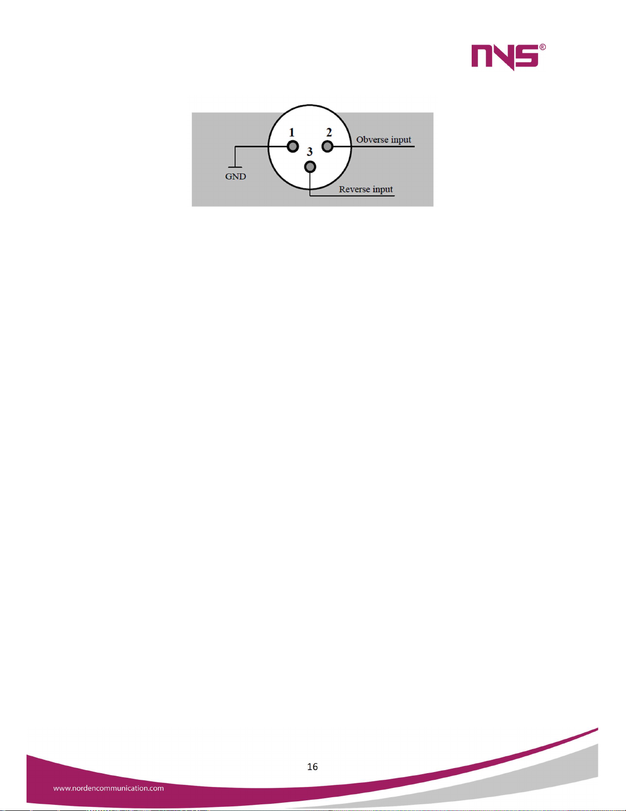
16
Three-wire XLR male plug
15. 6 common cameras connection ports
Each port allows connection to one camera.
All 6 cameras connected to this system must be of the same brand.
Cameras are connected by coaxial cable.
16. HD video output interface
Connect the projector and other video equipment, Input the camera content
to the big screen.
17. Common Video output port
The port is used for connection to projectors or other video equipment, with
which the content captured by cameras will be output to a large screen.
18. 6 HD camera connection port
Each port allows connection to one camera.
All 6 cameras connected to this system must be of the same brand.
Cameras are connected by coaxial cable.
19. These marks indicate that this machine can be safely working in areas under altitude
of 2000 meters and no tropical regions.

17
Specifications
Item Index Parameters
LINE input voltage 250 (±30) mV
ALARM input voltage
250 (±30) mV
LINE output voltage 1 (±0.1) V
BALANCE output voltage
1 (±0.1) V
Frequency Response
20Hz
-
20kHz
(
±3dB
)
SNR
>80 dB
Harmonic Distortion
<0.3%
Output Power
≤110W/3
-
way, 24V
Maximum Power
350W
Static power consumption 15W
Quantity of maximum units
128 ps
Control interface RJ45, RS232, RS422
Power source
AC220V~50Hz/320W
Package dimensions(L×W×H)
525×480×185mm
Equipment dimensions(L×W×H)
484×385×88 mm
Gross Weight
7.5kg
Net weight 6.9kg
This specification is subject to change without notice.
18
NVS-DC600083CE Conference System Extension Controller
Features
It works with the conference host to extend the maximum number of conference
units.
In a conference system, it supports up to 32 extended hosts.
8P-DIN sockets: One for connection with conference host and three for connection
with conference units.
An extended host allows connection of up to 128 conference units.
2U luxurious cabinet design, with fashionable and artistic appearance.
It may be installed on a 19-inch standard cabinet and is easy to install and space saving.
The equipment casing is made from metal materials and all the lines and casing are
properly grounded, so the system has an anti-static of 10kV in case of physical contact
and 15kV in case of air contact.
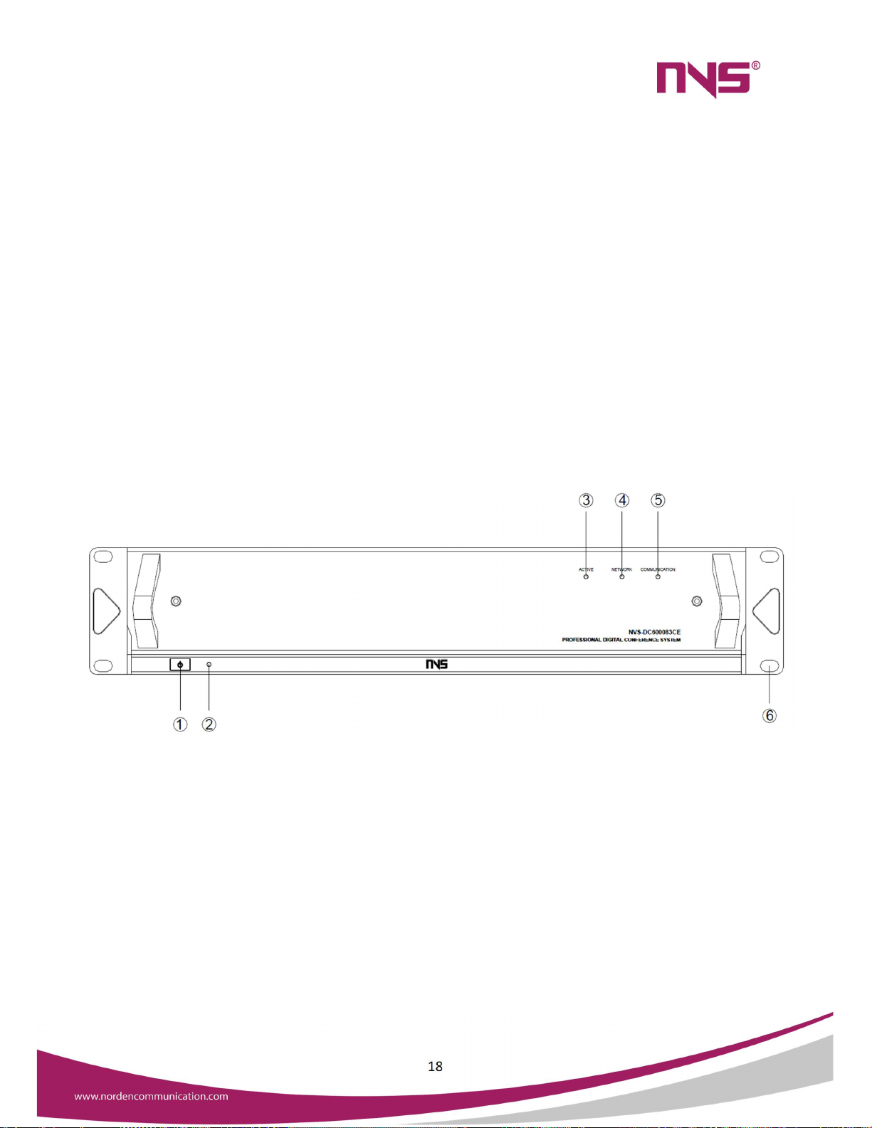
Front Panel
1. Power switch (POWER)
Power is on when the button is pushed down and is off when the button is ejected.
2. Power indicating light on extended host (ON)
The indicating light will be on,
when the system is powered on, and it is
off when the system is powered off.

19
3. Signal indicator (ACTIVE)
This indicating light will flicker
when the conference unit connected to
the extended host sends signals to the conference host.
4. Signal indicator (NETWORK)
This indicating light will flicker when there is communication between the conference
host and the extended host.
5. Signal indicator (COMMUNICATION)
This indicating light will flicker when the conference host sends signals to a conference
unit connected to the extended host.
6. Screw holes for installation in cabinets
Rear Panel
1. DIP switch for address settings (ID)
In order to tell the 31 extended hosts from one another, it is necessary to set a
unique ID for each extended host. See description in Page 35 for procedures of
setting up ID of an extended host.
2. Extended input port (ROUTE INPUT)
This port on the first extended host is connected to the ROUTE extended port on the
conference host, and such port on all other extended hosts will be connected to the
ROUTE OUTPUT port of another host.
Table of contents
Other Norden Controllers manuals


