Norden NVS-DC900013CH User manual

NVS-DC900013CH
Digital Conference System Controller
User Manual
1
The Installation and Operation Manual of the series Digital conference system
controller includes detailed description with respect to installation and operation of all
features the conference system. This Manual mainly includes description of the functions and
ports of all equipment units in the series conference system, graphic illustration of connection
between equipment, description of system configuration and operation instructions as well
as precautions and technical indexes. Please read this Manual carefully before disassembly of
the equipment and preparation for installation, in order to install and operate the equipment
properly. Please keep this Manual in good custody for future reference. For other information
or parameters with respect to the equipment uncovered in this Manual, please contact the
local dealer or after-sales service personnel of our Company.
About this User Manual
This User Manual is available and effective upon completion of
development of the Series intelligent digital conference system. The User Manual
includes system description, matters needing attentions in use, instructions on
system connection, instructions on use of product and technical specifications of
the Series intelligent digital conference system. Please read this User Manual
carefully before connection, installation and use and operate in accordance with
corresponding instructions in the Manual.
This symbol on the rear panel indicates matters needing attentions, please
use or operate the production accordance with corresponding instructions.
Please keep this User Manual in good custody for future use.

2
INDEX
1. System Overview………………………………………………………………………………………………………….4
2. Host front panel …………………………………………………………………………………………………………. 5
3. Host rear panel ……………………………………………………………………………………………………………5
4. Conference Microphone unit ………………………………………………………………………………………6
5. System Connection diagram ………………………………………………………………………………………..7
6. Instructions for use ……………………………………………………………………………………………………..8
1) Meeting Mode …………………………………………………………………………………………………8
2) Talk Number ……………………………………………………………………………………………………9
3) Configuring / Allocation address ……………………………………………………………………10
4) Language selection ………………………………………………………………………………………..11
5) Backlight time ………………………………………………………………………………………………..11
6) Voice control settings …………………………………………………………………………………….12
7. Connect with the power amplifier ……………………………………………………………………………..12

3
NVS-DC900013CH

4
System Overview
This system is a perfect combination of hand-in-hand one-line eight-core and dual-
backup all-digital intelligent control technology with network interface. It is simple to operate
and easy to install. The system adopts high-speed CPU program editing control, high-fidelity
circuit design, to reproduce the original sound quality, system unit automatic detection,
innovative speech mode setting, speech limited time function setting, becoming a new
generation of multifunctional conference system, it is a hotel, hotel, government Ideal system
solutions for various types of projects such as conference for offices, enterprises and
institutions, and multi-functional conference rooms.
Features
This Conference System uses eight-core all-digital high-fidelity circuit development
and design.
This Conference System host has 2 outputs, which can connect 120 units in total.
Equipped with a recording output interface, all meeting records can be completely
recorded and saved, and the audio output can also be connected to an external audio
amplifier.
This Conference System adopts unique high-fidelity audio processing circuit to
improve the clarity of the entire system.
It has Built-in RISC high-performance CPU as the core that offers stable system, and
fast calculation.
The Conference System host adopts liquid crystal display, and the menu operation is
more spontaneous and user friendly.
The System speech mode has first-in first-out, fully open mode, chairman mode, etc.
The Chairman Unit can use the priority button (Priority) to control the order of
speaking and control the atmosphere of the meeting.
The Conference unit is powered by the system host, and the working voltage is DC
24V, which meets safety standards.

5
Host Front Panel
1. Power switch indicator: POWER: Power switch
2. Display window: display system settings and working conditions.
3. Buttons for setting and modifying system functions, SET: execute the on-screen
menu function (press to confirm); Screen menu function left, right, up, and down
selection.
Host Rear Panel
1. Fuse mounting seat, install a 2.5A fuse.
2. AC power input socket, connected to AC 220V power supply.
3. RS-232 interface.
4. Line input and output ports, which can be connected to other audio
equipment for re- cording and playback.
5. Auxiliary volume adjustment knob.
6. System audio output interface, connected to the mixer input.
6
7. Output volume adjustment knob.
8. The chairman and representative unit connection sockets are divided into
2 connections. (Each port can be connected to a maximum of 25)
9. The RJ45 network and population of the chairman and representative units
are connected in 4 ways. (Each port can be connected to a maximum of 20)
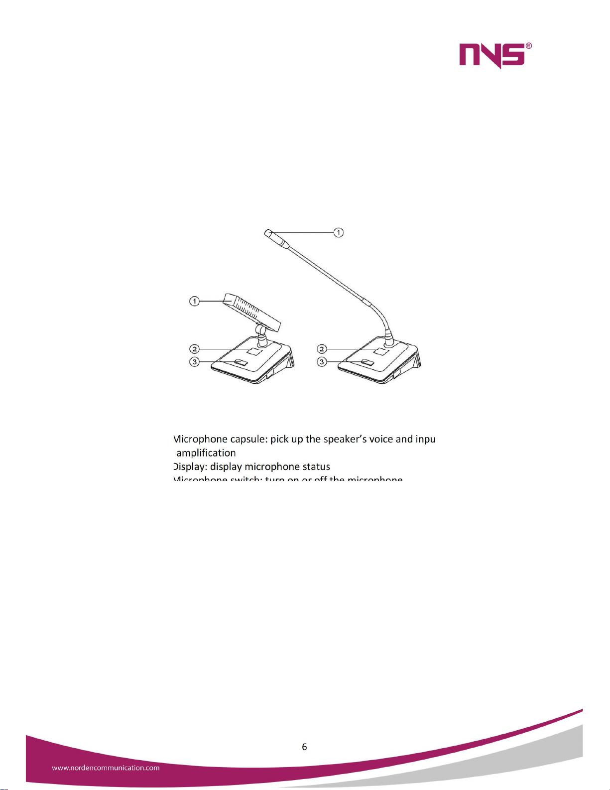
Conference Microphone unit
1. Microphone capsule: pick up the speaker’s voice and input it to the system
for amplification
2. Display: display microphone status
3. Microphone switch: turn on or off the microphone
4. External speaker: when other conference microphones speak, it can emit
sound
System connection diagram
8-Pin DIN Conference Cable Connection

7
Cat-6 Network Cable Connection
Instructions for use

8
1. Meeting Mode
Press "ENTER" to enter the main menu to set the conference mode, as shown on the
right, the cursor is at the "1"position.
After pressing the "ENTER" key to enter the conference mode, the display is as follows.
At this time, press the "UP" "DOWM" keys to move the cursor up and down, and select the
mode to be modified for setting
When a certain mode is selected, if the cursor is in the "automatic mode", press the "ENTER"
key to confirm.
Each mode is explained as follows:
Auto mode: This mode is when the opened microphone unit reaches the maximum number
of simultaneous speakers of the microphone unit (for the number of people setting, see the

9
setting of the next menu), the most advanced delegate microphone unit is automatically
turned on when the next microphone is turned on shut down. Keep the number of
microphone units that speak the most, but the chairman unit is not controlled by this, that is,
the chairman unit will not be turned off by the microphone that is turned on later.
Full open mode: After this mode is selected, all microphone units can be turned on. Chairman
mode: In this mode, only the chairman unit can be opened to speak, and the representative
unit cannot be opened.
2. Talk Number
This menu is to set the maximum number of microphone units to speak at the same
time. When the cursor is placed on the 2 mode control menu in the interface shown on the
right, press "ENTER" to enter.
Talk Number When the cursor is positioned on the 2 "Number of Speakers" menu on
the main menu, press the "ENTER" key to enter and the interface shown on the right will be
displayed.
At this time, you can press the up and down keys to adjust the maximum number of
microphone units speaking at the same time. The number can be selected from 1 to 6 all.

10
When a certain number is selected, press the "ENTER" key to automatically save and return
to the previous menu interface.
3. Cfg. Address
When the cursor is positioned on the 3 "Edit Address" menu on the main menu, press the
"ENTER" key to enter and the following interface will be displayed.
Press "ENTER" to enter, and the interface will be displayed as shown on the right: the
number of delegates and chairpersons displayed on the screen indicates the number of units
programmed in the system. If the system microphone unit has not been newly installed with
an address number or the system has increased the number of microphone units, engineers
must first reprogram all units with an independent microphone unit address number.
Repeated unit numbers will cause unpredictable errors. Generally, all microphones in the
system only need to be assigned an address once, and there is an independent unit number,
and there is no need to set it again when using it in the future.
The method of setting the unit number is when all the units are connected to the host in
turn, after entering this interface, press the up key ("UP" key, rotate to the right) to enter the
allocation unit number address, the display on the screen The number of delegates and
chairpersons are reset to zero. At this time, the indicator lights of all microphone units are
flashing, prompting to allocate unit number addresses, and then press the microphone switch
one by one in turn. Each time you press a microphone unit, the unit indicator stops flashing
and automatically Save a unit number, and the unit number will be automatically arranged
down according to the order of the microphones. The following figure shows that 2
representative units and 1 chairman unit have been set up, and the next one is the No. 3
representative unit or the No. 2 chairman unit. After all units have been edited, press "ENTER"
to return.
4. Language Selection

11
This function is to select the language displayed on the display screen of the machine.
There are Chinese and English options. After pressing the "ENTER" key to enter, you can press
the "UP" and "DOWN" keys to move the cursor up and down to select the appropriate
language, and then press the "ESC" key after selection Just go back.
5. Backlight time
When the cursor is positioned on the 6 "Backlight Time" menu on the main menu, press
the "ENTER" key to enter and the following interface will be displayed; Press "ENTER" to enter
and display the interface on the right: you can press the up and down keys to select whether
the backlight of the host dis- play will automatically turn off after not pressing any key of the
host, 10 seconds, 30 seconds, 1 minute, 5 minutes and long Five options are illuminated, after
selecting a time, press the "ENTER" key to automatically save and return to the previous menu
interface.
6. Voice Control Settings

12
When the cursor is positioned on the 6 " Voice Control Settings" menu on the main menu,
press "ENTER" to enter, and the following boundary surface will be displayed. Press "ENTER"
to enter and the screen on the right will be displayed. You can press the up and down keys to
select whether the voice control function is allowed or forbidden. When it is allowed, the
microphone unit will be automatically turned on if you speak at the microphone head of the
microphone unit when the microphone unit is not turned on.
Note: After the system enters any menu, if no button is pressed, the system will automatically return
to the main interface after 64 seconds
Connect with power amplifier
Turn the volume of the power amplifier to the minimum, press the microphone switch
on the chairman or the representative unit. After the microphone is turned on, speak into the
microphone. At the same time, slowly adjust the power amplifier volume potentiometer to
the appropriate position and pay attention to the position of the speaker. Try not to face the
microphone to prevent howling. Each chairperson and representative unit should be checked
again to see if each unit emits sound. During use, you can increase or decrease certain volume
on the main unit according to your needs to make it compatible with the sound of the entire
venue. match.

13
CAUTION
When the power switch is "OFF", the machine is not completely disconnected from the
power grid. For the sake of safety, please pull the power cord plug out of the socket when
not using the equipment.
The equipment shall not be subject to water drops or splashes, and objects such as vases
filled with water shall not be placed on the equipment.
To reduce the risk of electric shock, do not remove the cover. If necessary, please ask
professional personnel to repair.
The symbol on the rear panel indicates hazardous live. The connection of these terminals
must be operated by the instructed person.
The equipment is connected to the power grid through the power cord plug. In case of
equipment failure or danger, the connection between the unit and the power grid can be
disconnected by pulling out the power cord plug. Therefore, it is required to place the power
socket to a position where the power cord can be plugged and unplugged conveniently.

Table of contents
Other Norden Controllers manuals


Popular Controllers manuals by other brands


MOVETEC
MOVETEC LTC Series Installation and operating instruction

Honeywell
Honeywell TheraPro HR90 owner's guide

LEGRAND
LEGRAND ADMHRM4 installation instructions

Tech Controllers
Tech Controllers EU-R-9b user manual

Johnson Controls
Johnson Controls A25 Series Technical bulletin

Viconics
Viconics VT8000 Series User Interface Guide


