Norden NVS-AC10002PC User manual

www.nordencommunication.com
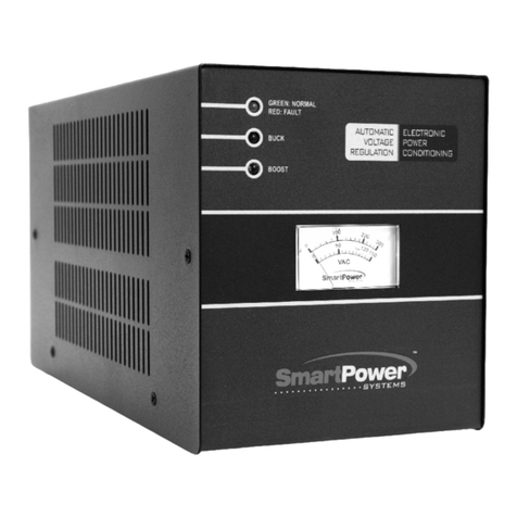
EMERGENCY POWER
CONTROLLER
User Manual
NVS-AC10002PC

Caution
corresponding instructions.
This symbol indicates "compulsory content"
Please make sure that the
power wire is NOT damaged.
Do NOT unplug the equipment
by pulling the power wire;
otherwise it may cause electric
shock, short circuit or fire.
When the equipment is in use, DO NOT block the air
outlet which should be kept clear, in order to avoid
overheat.
Do NOT store this
equipment in any
place with heavy dust
or vibration, or where
it is extremely cold or
hot.
Please do NOT place any heavy article on this
equipment. Please operate
switches, buttons or
external audio source
carefully.
Please prevent foreign matters (such as paper, metal
etc.) entering the equipment through the gaps or
opening, in such cases, please cut off the power supply
immediately.
Do NOT attempt to remove any internal component
from the equipment, or to
modify the equipment in
whatever manner.
In case that sound is suddenly off or there is
abnormal odor or smoke, please unplug the equipment
from the power socket to avoid potential electric
shock, fire or other accident. The equipment should be
inspected by professional personnel.
Smell of scorching
If the equipment is not in use for a long period, please
unplug it from the AC power socket to realize zero energy
consumption.
Smell of scorching
PROFESSIONAL PERIPHERAL
DEVICE
Emergency Power System
MAG2122E
POW E
R
OUTPUT VOLTAGE
DC
Contents
I.
FEATURES ...............................................................................................................................................……1
II.
APPEARANCE FUNCTION INTRODUCTION...................................................................................................1
2.1. FRANT PANEL INTRODUCTION………………………..……………………………………………………………………………1
2.2. REAR PANEL INTRODUCTION………………………………………………………………………………………………..…….2
2.3. SYSTEM CONNECTION…………………………………………………………………………………………………………………3
SPECIFICATION ...................................................................................................................................................3
CAUTION ............................................................................................................................................................ .4
1
1
1
2
3
3
4

NORDEN - Emergency Power Controller User Manual 1
Content
About the Manual 1
1. System Overview 2
1.1 Overview 2
1.2 Features 2
2. NVS-50010508EV Host/ NVS-50020508EV Extended Host 3
2.1 Product display 3
2.2 Features 3
2.3 Front panel 4
2.4 Rear panel 7
3. NVS-5003PM16EV / NVS-5007EX16EV (Remote paging MIC/ Extended keyboard) 11
3.1 Product display 11
3.2 Features 11
3.3 Front panel 12
3.4 Rear panel 13
4. NVS-5004FM04EV Fireman MIC 15
4.1 Product display 15
4.2 Features 15
4.3 Front & Rear panel 16
5. System structure 19
5.1 System structure 19
5.2 System connection diagram 20
5.3 Host and extended host connection diagram 21
6. Operation instructions 22
6.1 Manual playback host input audio 22
6.2 Manual playback EVAC voice 22
6.3 Automatic trigger EVAC voice 22
6.4 Emergency MIC paging operation 23
6.5 NVS-5003PM16EV paging MIC operation 23
1) Grouping settings 32
2) Control settings 34
3) Running status 36
4) Timing settings 38
5) Log settings 39
6) System settings 40
9. Installation 51
9.1 NVS-5004FM04EV Fireman MIC installation dimension 51
9.2 Installation steps 51
10. Packing list 53
Schedule: Zone Address and Dial Code Setting Comparison Table 55
.................................................................................................................................
............................................................................................................................
......................................................................................................................
......................................................................................................................
....................................................
..........................................................................................................
......................................................................................................................
..................................................................................................................
...................................................................................................................
..............................................................................................................
............
............................................................................................................
......................................................................................................................
.................................................................................................................
..................................................................................................................
..............................................................................................................
...................................................................................................
..........................................................................................................
.....................................................................................................................
.....................................................................................................
.............................................................................................................
............................................................................................................................
.......................................................................................................
......................................................................................
........................................................
..................................................................................................................
..........................................................................
.....................................................................................
..................................................................................
.............................................................................
................................................................
......................................................................................................................
...................................................................................................
...............................................................................................
..............................................................................................
......................................................................................................
.........................................................................................................
............................................................................................................
...........................................................................................................
...............................................................................................................
.........................................................................................................
...........................................................................................................
........................................................................................................................................
.........................................
.......................................................................................................
....................................................................................................................................
..................................................
PROFESSIONAL PERIPHERAL
DEVICE
OUTPUT VOLTAGE
DC
POW E
R
Ⅰ. Features
The maximum of output power is no less than 2 kW.
Support 1 KW equipment emergency operation up to 1 hour or more.
Built-in automatic battery charger with overcharge and over discharge protection.
Digital battery voltmeter, real-time display battery voltage.
Accepts PC remote monitoring function.
Ⅱ. Function Introduction
2.1 Front Panel Introduction
1 2 3 4 5 6 7
1. Switch : Press 1 to turn on the power and press 0 to turn off the power.
2. Power indicator : The indicator light is on when the power is turned on and the indicator
goes off when the power is turned off.
3. Digital battery voltmeter : Display of the output voltage value.
4. DC24V output indicator : The indicator lights up when the 24V DC voltage is output, to put
it in another way, the indicator will light up when the equipment is working.
5. Power charging indicator : This indicator is on when the device is being charged. When this
device is turned on, this indicator is off.
6. Protection indicator : When the charger’s voltage inside the device is lower than 24V, this
indicator flashes when the voltage is 20V-21V and the internal alarm beep is intermittent. When
the voltage is 20V, the indicator light is on and the alarm buzzer will be buzzing for a long time.
7. Cooling air inlet : It is a cooling window.

NORDEN - Emergency Power Controller User Manual
2
About the Manual
installation and use.
NVS-50010508EV (System host)
NVS-50020508EV (Extended host)
NVS-5003PM16EV (Remote paging MIC)
NVS-5007EX16EV (Extended keyboard for remote paging MIC)
NVS-5004FM04EV (Fireman MIC)
PROFESSIONAL PERIPHERAL
DEVICE
OUTPUT VOLTAGE
DC
POW E
R
Ⅰ. Features
The maximum of output power is no less than 2 kW.
Support 1 KW equipment emergency operation up to 1 hour or more.
Built-in automatic battery charger with overcharge and over discharge protection.
Digital battery voltmeter, real-time display battery voltage.
Accepts PC remote monitoring function.
Ⅱ. Function Introduction
2.1 Front Panel Introduction
1 2 3 4 5 6 7
1. Switch : Press 1 to turn on the power and press 0 to turn off the power.
2. Power indicator : The indicator light is on when the power is turned on and the indicator
goes off when the power is turned off.
3. Digital battery voltmeter : Display of the output voltage value.
4. DC24V output indicator : The indicator lights up when the 24V DC voltage is output, to put
it in another way, the indicator will light up when the equipment is working.
5. Power charging indicator : This indicator is on when the device is being charged. When this
device is turned on, this indicator is off.
6. Protection indicator : When the charger’s voltage inside the device is lower than 24V, this
indicator flashes when the voltage is 20V-21V and the internal alarm beep is intermittent. When
the voltage is 20V, the indicator light is on and the alarm buzzer will be buzzing for a long time.
7. Cooling air inlet : It is a cooling window.
FUSE
RATING
F2AL
~110-
115V
:
~220-
230V
OUT1
OUT2
OUT3
OUT4
OUT5
+24V/20A +24V/20A +24V/20A +24V/20A
+24V/20A
+24
V
~115V-230V/50Hz-
60Hz/300W
GN
D
CAUTIO
N!
GN
D
RISK OF ELECTRIC
SHOCK
DO NOT
OPEN
DATA
IN
DATA
OUT
2.2 Rear Panel Introduction
3
1 2 4 5 6 7 8
1
Remote control input
Connect to the remote control output interface of the previous device.
2
Remote control output
Connect to the remote control signal input of the next device.
3
OUT1~OUT5 DC24V output
24V emergency voltage output .
4
Positive pole input
Battery NVS-AC10002PC positive terminal input.
5
Negative pole input
Battery NVS-AC10002PC negative terminal input.
6
Cooling fan
Used for heat dissipation.
7
Power supply fuse
Used to fix the AC power fuse. If the fuse is broken, replace it by a fuse with the
same specifications.continuous fuse-broken indicates the device is in fault.
8
AC power cable
Plug the AC power cable into this outlet.

NORDEN - Emergency Power Controller User Manual 3
NVS Voice Evacuation System supports timing programming and manual oper
-
-
exhibition halls.
1.2 Features
•Meet the European Voice Alarm Control and Indicating Equipment Standards and 3CF
•
in emergencies;
•
status;
•
•
operation;
•
•
•Support emergency broadcast dual-audio output and background broadcast without
•
•
•
•
system;
•With dry contacts and override plug-in power output to provide trigger signal sources
•
zones
•
•
etc.;
•With 6 external audio inputs and 1 XLR output;
FUSE
RATING
F2AL
~110-
115V
:
~220-
230V
OUT1
OUT2
OUT3
OUT4
OUT5
+24V/20A +24V/20A +24V/20A +24V/20A
+24V/20A
+24
V
~115V-230V/50Hz-
60Hz/300W
GN
D
CAUTIO
N!
GN
D
RISK OF ELECTRIC
SHOCK
DO NOT
OPEN
DATA
IN
DATA
OUT
2.2 Rear Panel Introduction
3
1 2 4 5 6 7 8
1
Remote control input
Connect to the remote control output interface of the previous device.
2
Remote control output
Connect to the remote control signal input of the next device.
3
OUT1~OUT5 DC24V output
24V emergency voltage output .
4
Positive pole input
Battery NVS-AC10002PC positive terminal input.
5
Negative pole input
Battery NVS-AC10002PC negative terminal input.
6
Cooling fan
Used for heat dissipation.
7
Power supply fuse
Used to fix the AC power fuse. If the fuse is broken, replace it by a fuse with the
same specifications.continuous fuse-broken indicates the device is in fault.
8
AC power cable
Plug the AC power cable into this outlet.
2.3 System connection
Specification
Maximum output power 2000VA,5 parallel channels are divided equally
output voltage DC24V
Maximum support time 1kW×1 hour
Battery input 24V
Switch time 0.5 seconds
Protection AC fuse(F2AL)Overcharge, over discharge
power supply AC110V-250V/50-60Hz
Package size(mm)(Long* wide*high)555×455×185
Machine size(mm)(Long* wide*high)484×349.5×88
Gross weight 8.2kg
Net weight 6.5kg
Performance specifications are subject to change without notice.
FUSE RATING
F2AL~110-115V
:
~220-230V
Peripherals
Peripherals
OUT1 OUT2 OUT3 OUT4 OUT5
+24V/20A +24V/20A +24V/20A +24V/20A +24V/20A
+24V
~115V-230V/50Hz-60Hz/300W
GND
CAUTION!
RISK OF EL ECTRIC S HOCK
DO NOT OPEN
DATA IN
DATA OUT
Interface
connected
with NVS-AC10003BC
GND

NORDEN - Emergency Power Controller User Manual
4
2.1 Product display
NVS-50010508EV Host
NVS-50020508EV Extended Host
2.2 Features
•
inemergencies;
•
•
•
•
music playback; 1-channel output to connect extender or backup records;
•
•
•
•8 trigger inputs (dry contacts and electrical level optional); 8 dry contacts trigger
•
record view and impedance testing parameters setting;
2.3 System connection
Specification
Maximum output power
2000VA,5 parallel channels are divided equally
output voltage
DC24V
Maximum support time
1kW×1 hour
Battery input
24V
Switch time
0.5 seconds
Protection
AC fuse(F2AL)Overcharge, over discharge
power supply
AC110V-250V/50-60Hz
Package size(mm)
(Long* wide*high)555×455×185
Machine size(mm)
(Long* wide*high)484×349.5×88
Gross weight
8.2kg
Net weight
6.5kg
Performance specifications are subject to change without notice.
FUSE RATING
F2AL~110-115V
:
~220-230V
Peripherals
Peripherals
OUT1 OUT2 OUT3 OUT4 OUT5
+24V/20A +24V/20A +24V/20A +24V/20A +24V/20A
+24V
~115V-230V/50Hz-60Hz/300W
GND
CAUTION!
RISK OF EL ECTRIC S HOCK
DO NOT OPEN
DATA IN
DATA OUT
Interface
connected
with NVS-AC10003BC
GND
Cautions
1.
Note for Security
Do not insert the power plug of the unit into the grid before connecting the system cable.
Ensure that the voltage input to the device is exactly the same as the voltage requirements of this
equipment,otherwise there is a risk of burning equipment.
There is a dangerous voltage inside the machine; the voltage is enough to cause electric shock; do
not open the case in order to avoid the risk of electric shock.
When the power supply of this equipment is off, the machine is not completely disconnected from the
powersupply. For safety reasons, please unplug the power plug from the outlet when the device is not
in use.
Do not place the device in a sub-cooled or overheated place.
To ensure that the working environment of the equipment is well ventilated to avoid heat at work
and the temperature is too high to cause damage to the equipment.
Unplug the power plug in noisy weather or for long time.
Before removing or reassembling any parts of the equipment, disconnect or re-connect any electrical
other plugs or connections to the equipment; be sure to unplug the power plug to ensure that the
equipment is completely disconnected from the grid.
When the equipment is faulty, non-professionals without permission please do not open the cabinet to
repair, in order to avoid accidents or increase the degree of damage to equipment.
Do not place any corrosive chemicals close to the equipment.
2.
After-sale service note
Since the date of purchase from the date of installation and use of the provisions of the normal use
within the scope of quality problems, the company will provide three years of free warranty (including
free replacement parts) services.
The user must show a warranty card, receipt and the sales invoice as a certificate.
The following conditions are excluded from the scope of free warranty:
1.Damage caused by improper installation, use or handling;
2.Damage caused by unusual circumstances (such as excessive power supply voltage or ambient
humidity,etc).
3.Product damage caused by natural disasters and other accidents;
4. The product body number is converted, altered or removed;
5.The product has been repaired or modified by not authorized person of the company;

NORDEN - Emergency Power Controller User Manual 5
2.3 Front panel
•
•
main powersupply;
•
calibration modeling;
•
• Equipment working status display: work/ fault /normal;
• External SD card interface, which can expand 8G storage space; external audio source,
recording, log, built-in EVAC voice, etc.;
• With monitoring function, built-in recording function, built-in timing programming function,
which can regularly program dry contacts to control power sequencer switch ;
• Can output dual audio simultaneously to ensure background playback is not aected by
emergency or business broadcast;
NVS-50010508EV Host
NVS-50020508EV Extended Host
Cautions
1.
Note for Security
Do not insert the power plug of the unit into the grid before connecting the system cable.
Ensure that the voltage input to the device is exactly the same as the voltage requirements of this
equipment,otherwise there is a risk of burning equipment.
There is a dangerous voltage inside the machine; the voltage is enough to cause electric shock; do
not open the case in order to avoid the risk of electric shock.
When the power supply of this equipment is off, the machine is not completely disconnected from the
powersupply. For safety reasons, please unplug the power plug from the outlet when the device is not
in use.
Do not place the device in a sub-cooled or overheated place.
To ensure that the working environment of the equipment is well ventilated to avoid heat at work
and the temperature is too high to cause damage to the equipment.
Unplug the power plug in noisy weather or for long time.
Before removing or reassembling any parts of the equipment, disconnect or re-connect any electrical
other plugs or connections to the equipment; be sure to unplug the power plug to ensure that the
equipment is completely disconnected from the grid.
When the equipment is faulty, non-professionals without permission please do not open the cabinet to
repair, in order to avoid accidents or increase the degree of damage to equipment.
Do not place any corrosive chemicals close to the equipment.
2.
After-sale service note
Since the date of purchase from the date of installation and use of the provisions of the normal use
within the scope of quality problems, the company will provide three years of free warranty (including
free replacement parts) services.
The user must show a warranty card, receipt and the sales invoice as a certificate.
The following conditions are excluded from the scope of free warranty:
1.Damage caused by improper installation, use or handling;
2.Damage caused by unusual circumstances (such as excessive power supply voltage or ambient
humidity,etc).
3.Product damage caused by natural disasters and other accidents;
4. The product body number is converted, altered or removed;
5.The product has been repaired or modified by not authorized person of the company;
Please keep the manual and warranty card.
Please contact your dealer or visit our website at www.nordencommunication.com, if you have any
questions orprecautions which are not mentioned in this manual.
If you encounter a malfunction during the warranty period, please contact our after-sale staff (or
dealer) for repair;
if the self-demolition or maintenance by non-company technical staff,
NVS-AC10002PC
will not bear the
responsibility of free warranty.
CAUTION
When the power switch of this equipment is in the "off" state, the machine is not completely disconnected
from the power supply. For the sake of safety, please unplug the power cord from the outlet.
The device can not withstand water droplets or water splashes and can not place items such as vases filled
with water on the device.
Do not open the machine cover to prevent electric shock. If necessary, by a professional certificate of
professional staff to repair.
The terminals marked with the symbol in the equipment indicate hazardous, and the operation of
connecting these terminals shall be carried out by the instructed person.
The device is connected through the power cord and the power grid. When the equipment fails or is
dangerous, unplug the power cord and disconnect the device from the power grid. Therefore, it is necessary
to place the power.
Table of contents
Other Norden Controllers manuals
Popular Controllers manuals by other brands
StoneL
StoneL Axiom AN Installation maintenance and operating instructions

fimotec-fischer
fimotec-fischer FS-26 operating instructions
HygroMatik
HygroMatik FlexLine Series manual
SCHUNK
SCHUNK ECM Assembly and operating manual

Nibe
Nibe Climacool CoolLogic UCA/W quick start guide
National Instruments
National Instruments NI PXIe-8133 installation guide
