Norden EBS-1 User manual
Read, Understand, and Follow this manual which provides information
and procedures to safely operate and maintain the attachment.
Euro Bale Spear
Owner Manual
MADE IN THE USA
EBS-1


Euro Bale Spear 3 Norden Mfg. LLC (877) 296-5851
CONTENTS
1. INTRODUCTION ..........................4
1.1 Intended Usage .......................4
1.2 Operator Orientation....................4
1.3 Specications .........................4
1.3.1 EBS-1Specications.............4
1.4 Serial Number Location .................4
1.5 Product Improvements ..................5
1.6 Disposal of Equipment at End of Useful Life . 5
1.7 Unanswered Questions .................5
2. SAFETY .................................6
2.1 General..............................6
2.2 Safety Alert Symbol ....................6
2.3 Safety Icons Nomenclature ..............7
2.3.1 Personal Protection /
Important Information ............7
2.3.2 Prohibited Actions ...............7
2.3.3 Hazard Avoidance ...............7
2.4 General Safety ........................8
2.5 Machine Related Safety .................8
2.6 Safety decals .........................8
2.7 Operation Safety ......................8
2.8 Transporting Safety ....................8
2.9 Storage Safety . . . . . . . . . . . . . . . . . . . . . . . . 8
2.10 Maintenance Safety . . . . . . . . . . . . . . . . . . . . 8
2.11 Training .............................8
2.12 Authorization/TrainingSign-OForm .....9
3. SAFETY DECALS AND LABELS ...........11
3.1 General Information . . . . . . . . . . . . . . . . . . . 11
3.2 Contact Information ...................11
3.3 How to Install Replacement Safety Decals . 11
3.4 Safety Decal Locations.................12
3.5 Safety decals ........................12
4. NOMENCLATURE .......................13
5. ASSEMBLY AND SETUP ..................14
6. USAGE .................................15
6.1 User Safety..........................15
6.1.1 Machine Operation Recommendations
15
6.1.2 Machine Requirements ..........15
6.2 MachineSpecications.................16
6.3 Attaching to Machine ..................16
6.4 Pre-Operation Checklist ...............17
6.5 Usage..............................17
6.5.1 Picking Up a Bale ..............18
6.5.2 Moving with a Bale .............18
6.5.3 Placing the Bale ...............19
6.6 Detaching from Machine ...............19
7. TRANSPORTING.........................20
7.1 Highway and Transport Safety ...........20
7.2 Pre-transport Checklist.................20
8. STORAGE...............................21
8.1 Placing in Storage ....................21
8.2 Removing from Storage ................21
9. MAINTENANCE ..........................22
9.1 Maintenance Safety . . . . . . . . . . . . . . . . . . . 22
9.2 Practice Safe Service Procedures . . . . . . . . 22
9.3 Bolt Torque Requirements ..............23
9.4 Welding Repairs ......................23
9.5 Service Record ......................24
10. PARTS SECTION.........................25
10.1 Ordering Parts .......................25
10.2 Contact Information ...................25
10.3 Safety Decals and Instructional Labels ....25
10.4 EBS-1 Parts Detail ....................26

Norden Mfg. LLC (877) 296-5851 4 Euro Bale Spear
1. Introduction
The Norden Euro Bale Spear is an attachment that
mounts to a utility tractor equipped with a loader
having the ability to quick attach to attachments
following ISO 2326. It is designed specically to
move large bales of hay or straw.
Note: Thespecicterm“Attachment”willbe
referredtosimplyas“balespear”or
“attachment”throughouttherestofthis
manual and may refer to any of the models
covered by this manual. The term utility
tractorwillbereferredtoas“machine”
throughout this manual.
Read, understand, and follow the manual carefully
to become familiar with your new Norden bale spear.
Ultimately it is our desire that you will be operating
your bale spear as a seasoned professional in very
little time!
1.1 Intended Usage
Do not use this bale spear for any other purpose
than its intended use of moving large bales of hay
and straw.
Note: Do not use an oversized machine; the
attachment is intended to be used on
machines rated up to 120 HP or a 3500 pound
operating capacity.
1.2 Operator Orientation
The directions left, right, front, and rear, as
mentioned throughout this manual, are as seen from
the operator’s seat, facing in the direction of travel.
1.3 Specifications
Specifications subject to change without notice.
1.3.1 EBS-1 Specifications
Overall Width 42"
Overall Length 50.25"
Overall Height 20.1”
Overall Approximate Weight
120.8 lb.
Bale Spear Length and Quantity
49”x1
Bale Spear Socket
Conus 2
Bale Spear Rating (Each)
Frontofsockettoloadpointis19.68”
4,046 lbs.
Anti-Rotation Spikes - 1” Dia.
2
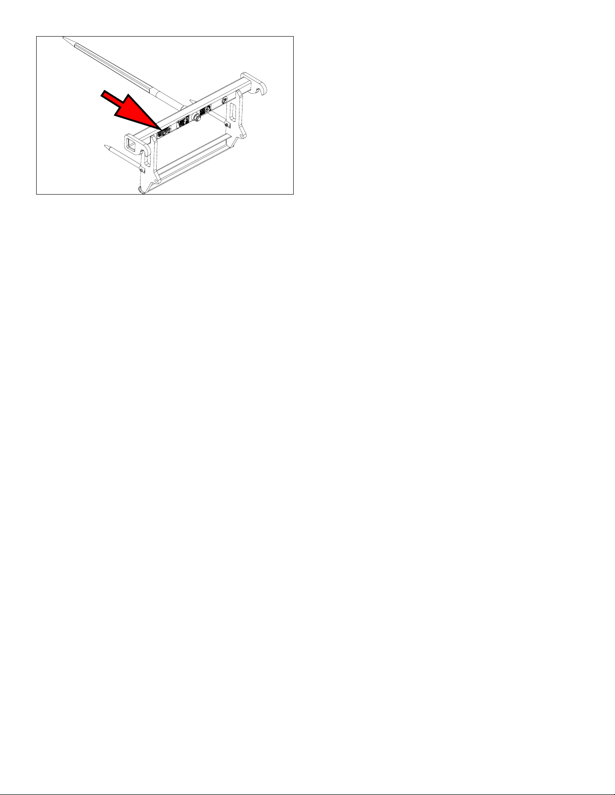
1.4 Serial Number Location
The bale spear’s serial number and model number
decal (1) is located on the back of the bale spear
frame. Please use these numbers when requesting
service, seeking information, or ordering parts.
1.
4210 Kinsman Rd NW, North Bloomeld, OH 44450
www.nordenmfg.com - (877) 296-5851
Made in USA
Serial Number
Mfg Date
Model Number/Rev
Max Hyd. Pressure
Load Rating
Approx. Weight
Part Number
1027460
Euro Bale Spear 5 Norden Mfg. LLC (877) 296-5851
EBS-1
Record the serial and model numbers as well as
the date of purchase in the space provided for easy
reference when contacting Norden Mfg LLC with
questions.
Model Number _____________________________
Serial Number ______________________________
Date of Purchase ___________________________
1.5 Product Improvements
Because Norden Mfg LLC maintains an ongoing
program of product improvement, we reserve the
right to make improvements in design or changes
inspecicationswithoutincurringanyobligationto
install them on attachments previously sold.
1.6 Disposal of Equipment at End of Useful
Life
The Norden Mfg LLC bale spears are designed
forthespecicpurposeofmovinglargebalesof
hay and straw. When this bale spear is no longer
capable of performing its intended use, it should be
dismantled and scrapped. Do not use any materials
or components from this bale spear for any other
purpose.
1.7 Unanswered Questions
If you have any questions not answered in this
manual, require additional copies, or the manual is
damaged, please contact your dealer or:
Norden Mfg LLC
4210 Kinsman Road NW
North Bloomfield, OH 44450
Phone: (877) 296-5851
Fax:(440)693-4336
E-mail: [email protected]
The manual is also available for download at:
www.nordenmfg.com
Norden Mfg. LLC (877) 296-5851 6 Euro Bale Spear
2. Safety
2.1 General
Most work-related accidents are caused by failure
to observe basic safety rules or precautions. An
accident can often be avoided by recognizing
potentially hazardous situations before an accident
occurs. As you use and maintain the bale spear you
must be alert to potential hazards.
Improper use and/or maintenance of this bale spear
could cause a dangerous situation that results in
property damage, personal injury, or death.
WARNING
Do not use the bale spear until you read,
understand, and follow the information
contained in this manual and all related
equipment manuals. Do not use the bale spear
for anything other than its intended purpose.
Safety precautions and warnings are
provided in this manual and on the bale
spear. If these precautions and warnings are not
followed, bodily injury or death could occur to
you or to other persons.
Norden Mfg LLC cannot anticipate every possible
circumstance that might involve a potential hazard.
The warnings in this manual and on the product are,
therefore, not all-inclusive. If a method of operation
notspecicallyrecommendedbyusisused,you
must satisfy yourself that it is safe for you and for
others. You should also ensure that the attachment
will not be damaged or be made unsafe by the use
or maintenance methods that you choose.
Theinformation,specications,andillustrationsin
this manual are based on the information that was
available at the time this material was written and
can change at any time.
2.2 Safety Alert Symbol
This is the safety alert symbol. It is used to
alert you to potential personal injury
hazards. The symbol is followed by a
signalwordsuchas“WARNING”or
“CAUTION”dependingontheseverityofthe
potential hazard. Obey all safety messages that
follow this symbol to avoid possible injury or death.
This manual contains WARNINGS, CAUTIONS,
NOTICES,SAFETYINSTRUCTIONS,andNOTES.
Warnings, Cautions, and Safety Instructions must be
followed to prevent the possibility of personal injury
or death due to improper operation. Notices and
Notes help prevent bale spear or property damage.
WARNING
Indicates a potentially hazardous situation
which, if not avoided, COULD result in death or
serious injury.
CAUTION
Indicates a potentially hazardous situation
which, if not avoided, MAY result in minor or
moderate injury.
NOTICE
Indicates that bale spear or property damage
can result if instructions are not followed.
SAFETY
INSTRUCTIONS
Indicates specific safety-related instructions or
procedures.
Note: Contains additional information important to
operation or a procedure.

Euro Bale Spear 7 Norden Mfg. LLC (877) 296-5851
2.3 Safety Icons Nomenclature
This manual and the bale spear has numerous
safety icons. These safety icons provide important
operating instructions which alert you to potential
personal injury hazards
2.3.1 Personal Protection /
Important Information
Read the manual
Maintenance procedure
Eye protection
Hearing protection
Hand protection
Foot protection
First aid kit
Use proper tools
OEMOEM
Use OEM parts
Use ROPS and seat belt
Maintain safety decals
Place in park
Remove key
STOP
Stop engine
Visibility - slow moving vehicle (SMV)
Set parking brake
2.3.2 Prohibited Actions
Do not alter or modify
Do not leave out tools
Do not weld
No riders
No children
No alcohol
No drugs
2.3.3 Hazard Avoidance
Crushing hazard
Crushing hazard
Slipping hazard
Tripping hazard
Falling hazard
Safety alert symbol
Defective or broken part
Falling hazard
Maintain safe distance
Pinch point hazard
Crush hazard
Rollover hazard
Not a lifting device
Entanglement hazard

Norden Mfg. LLC (877) 296-5851 8 Euro Bale Spear
2.4 General Safety
WARNING
Read, Understand, and Follow
Manual
To prevent personal injury or even death, be
sure you read, understand, and follow all of the
instructions in this manual and other related
OEM equipment manuals! This bale spear was
designed for a specific application; DO NOT
modify or use this bale spear for any application
other than that for which it was designed.
Attachments used improperly or by untrained
personnel can be dangerous! Inexperienced
operators should receive instruction from
someone familiar with the bale spear and the
machine before being allowed to operate the
bale spear.
Do Not Operate
Do not use the attachment if it is in
need of repair. If you believe the bale spear has
a defect which could cause injury or death, you
should immediately stop using the bale spear.
Fall Hazard
Do not use the attachment as a platform
for standing. Do not stand on top of the
attachment at any time. Do not hang on the
attachment or allow others to hang on it.
Pinch Point Hazard
Keep hands and feet away from
the attachment to prevent them from getting
pinched or crushed.
2.5 Machine Related Safety
Impaired User Hazard
Do not attempt to use or maintain
the attachment under the influence of drugs
or alcohol. Consult your doctor before using
the bale spear while taking prescription
medications.
Falling Hazard
Do not allow riders on the machine
or attachment at any time. Falling can result in
severe injuries or death.
WARNING
Stay Clear
Clear the area of people, especially
small children, before using the attachment.
Under no circumstances should young children
be allowed to work with or around the bale
spear.
Not A Lifting Device
Do not use the bale spear to lift other
objects.
2.6 Safety decals
Refertosection“3.SafetyDecalsandLabels”on
page 11 for safety recommendations related to
using the bale spear.
2.7 Operation Safety
Refertosection“6.1UserSafety”onpage15for
safety recommendations related to using the bale
spear. All applicable safety recommendations in
other sections should also be followed.
2.8 Transporting Safety
Referto“7.Transporting”onpage20forsafety
recommendations related to traveling with a
machine and attachment on a public roadway. All
applicable safety recommendations in other sections
should also be followed.
2.9 Storage Safety
Refertosection“8.Storage”onpage21for
safety recommendations related to storing the bale
spear. All applicable safety recommendations in
other sections should also be followed.
2.10 Maintenance Safety
Refertosection“9.Maintenance”onpage22for
safety recommendations related to maintaining the
bale spear. All applicable safety recommendations in
other sections should also be followed.
2.11 Training
Norden Mfg LLC follows the general Safety
StandardsspeciedbytheFarmEquipment
ManufacturersAssociation(F.E.M.A.),andthe
American National Standards Institute (ANSI).
Anyone who will be using and/or maintaining the
bale spear must read and clearly understand ALL
safety, operation, and maintenance information
presented in this manual, other related OEM

Euro Bale Spear 9 Norden Mfg. LLC (877) 296-5851
machine manuals, and the safety decals.
If you do not understand any information in this
manual, see your dealer or contact Norden Mfg LLC
before proceeding.
Do not use or allow anyone else to use this
attachment until all information has been reviewed.
Annually review this manual before the season start-
up.
MakeperiodicreviewsofSAFETYandOPERATION
a standard practice. An untrained operator is not
qualiedtousethisbalespear.
2.12 Authorization / Training Sign-Off Form
Theauthorizationandtrainingsign-oformis
provided for your records to show that all personnel
who will be working with the attachment have read
and understand the information in this Operator
Manual and have been trained in the operation of
the machine the attachment is connected to. The
user and the owner should both sign and date the
form to indicate acceptance of the risk of using the
bale spear.

Norden Mfg. LLC (877) 296-5851 10 Euro Bale Spear
Authorization / Training Sign-O Form
Date User’s Signature Owner’s Signature

Euro Bale Spear 11 Norden Mfg. LLC (877) 296-5851
3. Safety Decals and Labels
3.1 General Information
The types of safety decals (hazard labels) and
instructional labels, along with their locations on the
bale spear, are shown in the following illustrations.
Good safety practices require that you familiarize
yourself with the various safety decals, the type
of warning, and the area or particular operation
relatedtothatareathatrequiresyourSAFETY
AWARENESS.
THINK
SAFETY!
Think SAFETY!
Work SAFELY!
Pay close attention to the safety decals and
instructional labels attached to the machine and bale
spear.Thesafetydecalsaxedtothebalespear
are reproduced in this section. If the bale spear is
missing a label or one is unreadable, replace the
label before using the bale spear.
SAFETY
INSTRUCTIONS
Safety Decals and Instructional Labels
1. Keep safety decals or instructional labels
clean and legible at all times. Use a clean,
damp cloth to clean safety decals.
2. Replace any missing or hard-to-read safety
decals or instructional labels.
3. Use care when washing or cleaning the bale
spear not to remove or damage the decals.
When using a pressure washer to clean
the bale spear, avoid spraying too close
to decals; high-pressure water can enter
through very small scratches or under edges
of decals causing them to peel or come off.
4. Locations for the decals and replacement
part numbers are shown in this section.
5. Replacement parts must have replacement
decals attached before the bale spear is
used.
6. Decals are available from your authorized
dealer or from Norden Mfg LLC at no charge.
3.2 Contact Information
Forreplacementdecals,contact:
Norden Mfg LLC
4210 Kinsman Road NW
North Bloomfield, OH 44450
Phone: 877-296-5851
Fax:440-693-4336
E-mail: [email protected]
3.3 How to Install Replacement Safety
Decals
1. Clean and dry the installation area.
Note: Do not install the signs if the temperature is
below50°F.
2. Determinetheexactpositionbeforeyouremove
the backing paper.
3. Remove the backing paper.
4. Align the safety decal or instructional label over
thespeciedareaandcarefullypressthesignto
the part/frame.
Note: Small air pockets can be pierced with a pin
and smoothed out using the piece of backing
paper or plastic card.
Norden Mfg. LLC (877) 296-5851 12 Euro Bale Spear
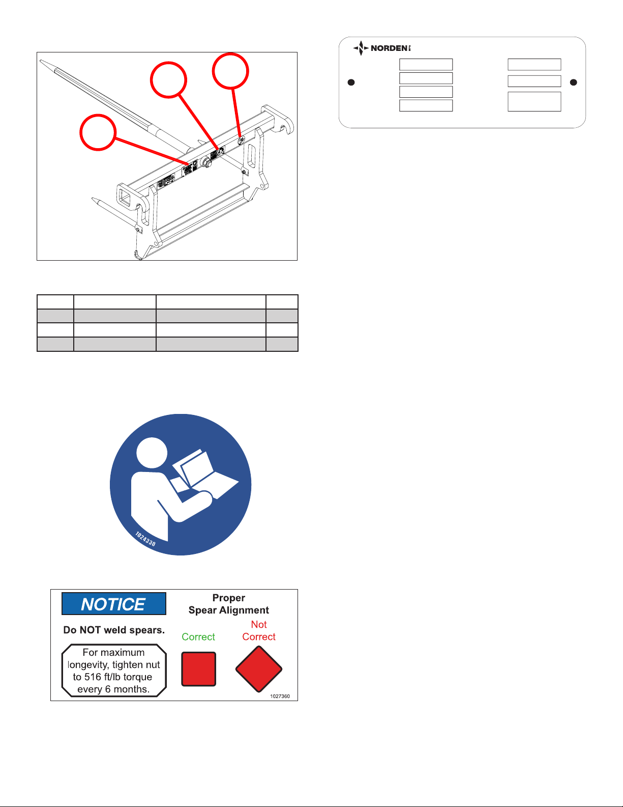
3.4 Safety Decal Locations
1
2
3
Item Type Description Qty.
1INFORMATIONAL Read the Manual 1
2 NOTICE Spear Orientation 1
3INFORMATIONAL Mfg Placard 1
3.5 Safety decals
1.
INFORMATIONAL — Read the Manual
2.
NOTICE — Spear Orientation
3.
4210 Kinsman Rd NW, North Bloomeld, OH 44450
www.nordenmfg.com - (877) 296-5851
Made in USA
Serial Number
Mfg Date
Model Number/Rev
Max Hyd. Pressure
Load Rating
Approx. Weight
Part Number
1027460
INFORMATIONAL — Manufacturer Placard
Euro Bale Spear 13 Norden Mfg. LLC (877) 296-5851
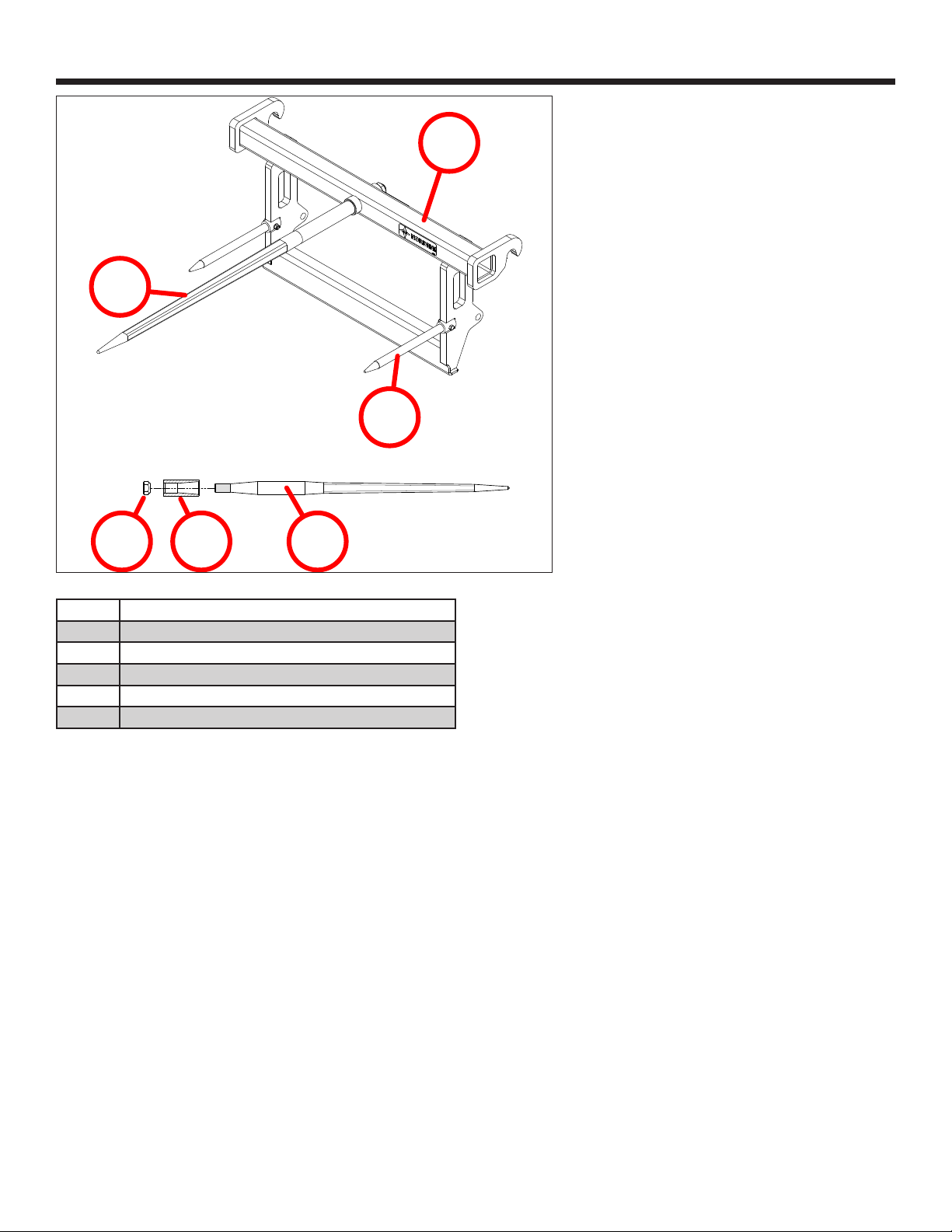
4. Nomenclature
1
2
3
4 5 1
Item Description
1 Spear
2 Anti-Rotation Spike
3Frame(weldment)
4 Spear Nut
5 Spear Sleeve (part of weldment)

Norden Mfg. LLC (877) 296-5851 14 Euro Bale Spear
5. Assembly and Setup
The factory will perform complete assembly of
the bale spears. Upon receipt, the operator must
conduct an initial visual inspection of the attachment.
If applicable, the operator must ensure that all nuts
and bolts are appropriately torqued before using the
attachment.
To orient the spear, the operator should place the
atfaceupwardsandtightenthenutto516ft/lbor
700 N·m. It is critical to ensure that the tapered side
of the nut is facing the socket, as failure to do so
may cause premature failure of the spear. A 41 mm
sockettsthenut–besurecorrecttoolsareused.
Note: Topreventoxidationfromseizingthespear
into the socket, the operator must apply
grease or an anti-seizing compound onto the
primary taper of the replacement spear.
NOTICE
Premature failure of spear may result from
improper tightening of the spear nut.
The operator should periodically make sure the nut
isproperlytightened(516ft/lbor700N·m).Failure
to do so may shorten the life of the spear.
Apply grease or anti-sieze all around full length of taper.
Do not apply grease or anti-sieze on threads or bevel.
Euro Bale Spear 15 Norden Mfg. LLC (877) 296-5851
6. Usage
6.1 User Safety
Referto“2.4GeneralSafety”onpage8for
additional safety information.
6.1.1 Machine Operation Recommendations
WARNING
STOP
Roll Away Hazard
Before leaving the
operator’s seat, make
sure the engine is stopped, the transmission
is placed in park, the key is removed, and the
parking brake is set.
Rollover Hazard
The weight of the machine, plus the bale
spear, if it rolls onto a person, could
cause serious crushing injury or death.
Crush Hazard
The machine must be equipped
with a Roll Over Protective
Structure (ROPS) and a seat belt. A crushing
hazard could occur if the operator is ejected
from the seat while the tractor is in motion.
Fasten the seat belt whenever the tractor is
moving.
Entanglement Hazard
If using a small compact or utility
tractor, keep hands and clothing
clear of any rotating parts. Stay clear of the bale
spear while the machine is moving.
SAFETY
INSTRUCTIONS
The following safety instructions are provided to
help prevent injury or limit bale spear damage.
SI
It is the owner’s responsibility to make
sure any person using a machine with the
attachment, especially if it is loaned or rented,
has been thoroughly trained on its proper and
safe use.
SI
Be certain only physically-able persons will
use the attachment.
SI
Users who have not read and understood
all operating and safety instructions are not
qualified to use the attachment.
SI
If the elderly are assisting with the work,
their physical limitations need to be
recognized and accommodated.
SI
Never allow children to use the attachment.
SI
Be especially observant of the operating
area and terrain – watch for loose fill,
holes, rocks or other hidden hazards. Always
inspect the area prior to operation.
SI
Be careful at the edge of ditches or gullies.
Be careful when working on inclines.
SI
Do not use excessive speed when moving
bales.
SI
Allow for bale spear length when making
turns.
6.1.2 Machine Requirements
WARNING
Machine Operator Manual
Always refer to the machine’s
operator manual to ensure
compatibility and maximum safety.
The machine must be equipped with a front-end
loader with Euro attachment mounting style rated to
lift the bale spear which can weigh up to 122 pounds
plus the weight of the bale.
SAFETY
INSTRUCTIONS
SI
Do not use an oversized machine; the bale
spears are intended to be used on
machines rated up to 120 HP or a 3500 pound
operating capacity.
SI
Using the bale spear with a machine that
exceeds the specified requirements may
cause machine or attachment damage, be a
potential danger to the operator or bystanders,
and will void any warranty.
SI
Always review the “controls” section of the
machine’s Operator Manual to be familiar
with the location, settings, and function of the
controls. Be familiar with all controls before
using this attachment.
Norden Mfg. LLC (877) 296-5851 16 Euro Bale Spear
6.2 Machine Specifications
This section is provided to give the operator general
safety information for the machine. Always follow the
OEM instructions given in the operator’s manual for
the machine.
WARNING
Rollover Hazard
To avoid serious injury or death
from falling, runover, rollover, or
crushing, the machine must have an approved
Roll-Over Protective Structure (ROPS) or ROPS
cab and seat belt.
1. The machine must be equipped with an approved
Roll-Over Protective Structure (ROPS) or ROPS
cab and seat belt.
a. If equipped with a folding ROPS structure,
keep it locked in the UP position.
b. Only operate the machine when seated in the
operator seat.
c. Always fasten seat belt whenever the machine
is moving.
2. If working around dry grass or vegetation, to
reducetheriskofre,donotuseamachinewith
anunder-frameexhaust.
3. Whenever traveling on a public roadway, follow
guidancegivenin“7.Transporting”onpage20.
4. Maintain all manufacturer’s safety shields and
guards
6.3 Attaching to Machine
WARNING
Pinch Point Hazard
Use caution when connecting the
attachment to the machine. Keep
hands and feet from under the attachment and
clear of pinch points between attachment and
machine. Do not allow anyone to stand between
the machine and pallet fork during attachment
process.
1. Ensure there are no potential unintended collisions
between the attachment and the loader before
connectingthemforthersttime.
2. Tilt the tool carrier forward completely to angle the
carrier arms downward toward the attachment.
Position the tool carrier an inch below the
attachment hooks.
3. Drive the machine forwards slowly, centering
the carrier arms between the hooks on the
attachment.
4. When the tool carrier makes contact with the
attachment, raise the loader to engage both hooks
of the attachment on the tool carrier.
5. Roll the tool carrier back toward the machine.
6. If equipped, the hydraulic or electronic powered
locking pins can be engaged. In this case; skip
Steps 7, 8, and 9.
7. If your loader requires manual locking, perform a
full roll back to automatically lock the attachment
onto the tool carrier.
8. If your loader requires a fully manual locking
process:
WARNING
STOP
Roll Away Hazard
Before leaving the
operator’s seat, make
sure the engine is stopped, the transmission
is placed in park, the key is removed, and the
parking brake is set.
a. Raise the back of the attachment slightly off
the ground and angle it back to apply pressure
against the stops.
b. Shut off the machine.
c. Apply the parking brake.
d. Manually lock the attachment to the carrier
assembly.
WARNING
Injury Hazard
To avoid serious injury or death
caused from falling attachment: lock
pins must completely engage attachment eyes.
Crush Hazard
Do not stand under raised
attachment.
9. If equipped, the attachment’s locking lug will
impact/push aside the Click-on system on the
tool carrier, automatically locking the attachment
in position. The lock lever is released and moves
tothe“lockedattachment”position.

Euro Bale Spear 17 Norden Mfg. LLC (877) 296-5851
10. Raise the loader arms until the tool carrier is
clearly visible from the driver’s cab. Inspect
alignment and verify positioning.
11. Pay attention to the tool carrier lock indicators,
whichmaydierdependingonthetypeoftool
carrier installed on the loader. Carefully observe
howyourspecictoolcarrierindicatesalocked
attachment.
12. Before starting work with the loader/attachment,
read“6.4Pre-OperationChecklist”onpage17
to ensure the attachment is correctly locked onto
the loader’s tool carrier:
• Visually check that the locking lever indicates a
locked attachment.
• Visually check that the tool carrier locking pins
are in the locked position.
13. Verify that the attachment is locked in place
on the tool carrier by pressing the front of the
attachment against the ground.
14. Before using the attachment, the operator must
operate it through its full range of motion and
conrmthattheattachmentissecureandsafe.
6.4 Pre-Operation Checklist
Before each use of the attachment, the following
areas should be checked.
Checklist Before Each Use
þTask
Make sure the bale spear is positively attached to the machine.
Referto“6.3AttachingtoMachine”onpage16.
If the machine uses tires, make sure they are inflated properly
and the lug nuts are tight.
Visually inspect the attachment for any loose bolts, worn parts,
or cracked welds. Make necessary repairs before using the
attachment.
Make sure the bale spear is not bent or cracked.
Make sure the operating area is clear, especially of children and
animals.
6.5 Usage
Before using the attachment, the operator must
have a complete understanding of how to operate
the machine including all controls, and how to use
the attachment.
The operator should read and understand the Safety
and Operation Sections of the machine operator’s
manual. It is important to note that these manuals
mustbereadandexplainedtoanyoperatorwho
cannot read. It is crucial to never allow anyone to
operate the machine or use the attachment without
complete operating instructions.
To ensure safety to the operator, bystanders, and
equipment, the operator must become familiar
with the surrounding work area and any obstacles
and hazards contained within before starting any
operation. Special attention should be paid to foreign
debris, rough terrain, steep slopes, bystanders, or
animals in the area.
If the operator is not already familiar with the
process, it is recommended to practice lifting,
lowering, maneuvering, and placing a bale on a
levelsiteuntilthecondenceandskillneededto
safely move bales. It is important to follow the safety
operating procedures that are spelled out in this
Operator’s Manual.
WARNING
Crush Hazard
When handling round bales,
improper use of the machine can
result in serious injury or death to the machine
operator. This could be caused by the bale
rolling backwards into the operator’s station.
Therefore, it is important to handle round bales
safely.
CAUTION
Tip Over Hazard
It is important not to exceed 3,500 lbs.
or the lift capacity of the machine. The
operator should not lift the bale too high,
creating an unstable and unsafe situation. The
operator should also avoid tilting the bale too
far forward, setting up a situation that could
cause the bale to prematurely slide off the
spear(s).
The operator must travel at a safe speed for
ground conditions. Travel slowly over rough
ground or when making turns. Working on or
around slippery or sloped areas could cause the
operator to lose control of the machine.
The operator must not allow bystanders, pets,
or livestock to approach the danger zone of the
working area.
The operator must not leave the machine with
the attachment raised off the ground.

Norden Mfg. LLC (877) 296-5851 18 Euro Bale Spear
6.5.1 Picking Up a Bale
1. Ensure that the weight of the bale does not
exceedthesmallerofthetwoliftcapacities
below:
• The rated lift capacity of the spears (4,046 lbs at
19.68”fromthefrontofthespearsleeve).
• 83% of the rated lift capacity of the machine.
Note: This calculation accounts for the increased
loader stresses caused by the added
extensionoftheattachmentandensures
that the front tires on your tractor are rated
properly for the job. Always fully insert the
spear into the bale before lifting it, as lifting
heavy or frozen bales without fully inserting
the spear can damage the unit and void its
warranty.
NOTICE
Care must be taken to ensure there is enough overhead
clearance and no potential hazards or obstructions that
could interfere with the lifting and placing of the bales.
2. Position the bale spear and push it into the
baleuntilitisrmlyagainsttheframeofthe
attachment. Always center the bale horizontally
on the spear points to optimize stability while
transporting.
3.
Target
Drive the spear into
the bale with the
spear level, centered
horizontally, and the
point of the spear at,
or slightly above, the
vertical center of the
bale, until the spear
is fully inserted and
the bale is against
the bale spear frame.
This will allow the anti-rotation spikes to stabilize
the bale.
Note: Soft center bales will tend to droop after being
lifted by a single spear. Placing the spear
in a lower position in the bale will allow for
more lifting height and lessen the load on the
stabilizer spikes.
NOTICE
Potential Machine Damage
Do not attempt to spear a round bale down from the top
if it is lying on its flat face, as excessive movement of the
machine while operating the loader can seriously damage
the machine and/or its hydraulic cylinders or hoses.
Instead, first tip the bale up on the round side.
SAFETY
INSTRUCTIONS
Transport bales at a height that maintains a
clear line of sight and keep the bale low to the
ground when possible to enhance stability.
4. Advanced operators should spear bales with a
slightly downward motion at a 5° downward angle
of the spear, and lower the boom as the spear
enters the bale to pinch the bale to the ground,
preventing it from sliding away. This method also
makesiteasiertoslidethebaleothespear.
5. After lifting the bale a short distance, tilt the spear
points up 5-10 degrees from horizontal to reduce
thelikelihoodofthebaleaccidentallyslidingo
the spear. Always check to ensure that the bale is
stable before traveling.
Note: Partial engagement of the spear(s) can
damage the spear(s), as it locates the weight
of the bale on the outer end of the spear(s).
Raise and roll back the bale just high enough to
provide ground clearance. If the bale appears
unstable, lower it, remove the spears, and repeat
therststepsuntilthebaleissecure.Tominimize
jerking, stop and start the loader gradually when
lowering or lifting loads.
SAFETY
INSTRUCTIONS
Always ensure the tractor is properly ballasted
before attempting to lift any load with the
attachment. If handling bales with both the
front-end loader and the 3 point hitch on the
tractor, always load the 3 point attachment first
and unload it last.
SI
Make sure that the work area is clear of
children, animals, and other obstacles
before using the attachment. This is particularly
important in areas with higher noise levels or
quiet cabs, as you may not hear people
shouting.
6.5.2 Moving with a Bale
Referto“7.Transporting”onpage22for
additional highway safety information.
CAUTION
Crush / Tip Over Hazard
Never attempt to stop a rolling bale
with the machine.
Euro Bale Spear 19 Norden Mfg. LLC (877) 296-5851
SAFETY
INSTRUCTIONS
SI
Watch for overhead obstructions and side
clearances while moving bales.
SI
Utilize tractors with wide front axles and
move all wheels to their maximum width
position to achieve the highest stability.
SI
Ensure tractors are correctly ballasted
according to the load being transported to
prevent the loss of steering control caused by
improper ballasting.
1. Raise the bale to the minimum height required
for the terrain that must be crossed with the bale.
2. During transport, keep the bale as close to the
ground as possible.
3. When transporting empty, ensure the spear
points are at a safe height and angle that does
not pose a risk of impaling people or livestock.
4. Transport bales fully against the spear frame
and with the spear points raised 5 to 10 degrees
from horizontal. Do not transport bales halfway
or more out on the spear points.
5. Lower the spear points to the ground when
stopped to prevent people or livestock from
being impaled. If the spear cannot rest on the
ground, point it downward for protection.
6. Use gradual acceleration, turning, and braking to
prevent any loss of control.
7. Reduce ground speed when turning and
maintainsucientclearancetoavoidobstacles
such as buildings, trees, and fences.
8. Avoid any obstacles, bumps, or holes in the path
to maintain stability.
9. Transporting bales over ramps, grades, bumpy
ground, soft surfaces, or slippery surfaces can
reduce machine stability and lift capacity and is
extremelydangerous.
10. Always travel straight up and down inclines,
avoid making turns, and keep the spear points
tilted up 5 to 10 degrees from horizontal
regardless of the angle of the incline.
11. When traveling on inclines greater than 10
percent, place the bale on the uphill side of the
machine, when necessary, drivers should drive
up and back down steep inclines.
12. Keep equipment away from electrical power
lines and place orange warning signs under
overhead electrical power lines to indicate the
danger.
13. Frequentlycheckthebaletomakesurethatit
has not become unstable during transport.
6.5.3 Placing the Bale
After the bale has been positioned and stabilized in
the desired location, tilt the spear slightly downward
toenablethebaletoslideothespear.Toprevent
the bale from sliding on the ground, it may be
necessary to apply a small amount of downward
pressure to it.
6.6 Detaching from Machine
CAUTION
Pinch / Crush Hazard
Use caution when disconnecting
the attachment from the machine.
Keep hands and feet from under the attachment
and clear of pinch points. Do not allow anyone
to stand near the machine or attachment when
disconnecting.
1. Movethemachineontoaat,level,solidsurface.
Lower the attachment slightly above the surface
with the hitch angled, front of the attachment
slightly higher than the rear.
2. If your machine is equipped with hydraulically
operated locking pins, retract the coupler lock at
this time. In this case; lower the attachment to
the ground and skip Steps 3, 4, and 5.
3. Shut down the machine and set the parking brake
properly without lowering the attachment.
WARNING
STOP
Unintended
Movement
Before leaving the
operator’s seat, make sure the engine is
stopped, the transmission is placed in park, the
key is removed, and the parking brake is set.
4. Move the locking lever to disengage the locking
pins.
5. Start the engine and lower the attachment to the
ground.
6. Tilt the tool carrier forward to allow the tool carrier
to clear the hooks on the attachment.
7. Make sure the area is clear of bystanders and
animals, then slowly back the machine away from
the attachment, ensuring that the tool carrier does
not interfere with the attachment.

Norden Mfg. LLC (877) 296-5851 20 Euro Bale Spear
7. Transporting
7.1 Highway and Transport Safety
This section is provided to give the operator general
safety information for the machine. Always follow the
OEM instructions given in the operator’s manual for
the machine.
Referto“2.4GeneralSafety”onpage8for
additional safety information.
SAFETY
INSTRUCTIONS
SI
Make sure the machine used is in good
operating condition according to the OEM
user’s manual.
SI
When traveling the attachment on the
highway, make sure the machine has
a clearly visible “Slow Moving Vehicle” placard.
SI
Use approved accessory lighting, flags, or
other necessary warning devices to protect
operators of other vehicles on the highway
during daylight and nighttime transport. Various
safety lights and devices are available from the
OEM of your machine.
SI
Do not allow anyone to ride on the machine
or the bale spear.
SI
Always drive at a safe speed relative to
conditions, and ensure that the speed is
low enough for an emergency stop. Keep speed
to a minimum.
SI
Reduce speed prior to turns to avoid the
risk of overturning.
SI
Always keep the machine in gear to provide
engine braking when going downhill. Do
not coast.
SI
Be a safe and courteous driver. Always
yield to oncoming traffic in all situations,
including narrow bridges, intersections, etc.
Plan your route to avoid heavy traffic.
SI
Travel on roadways in such a way that
faster moving vehicles can pass safely.
SI
Always travel with the attachment in a
position to provide maximum visibility at all
times. Make allowances for increased length
and weight of the bale spear when making turns,
stopping, etc.
7.2 Pre-transport Checklist
1. Before transporting, make sure the maintenance
on the machine is current.
2. If applicable, check the tire pressures on the
machine, and correct if necessary.
3. Make sure the attachment is securely attached
to the machine. Always inspect the bale spear
and frame for damage or abnormal wear before
attaching.
4. Prior to traveling on a public road, have an
observerconrmallrunninglights,brakelights,
turn signals, and hazard lights are working on the
machine.
5. Verify the brakes are operating correctly.
Table of contents
Other Norden Farm Equipment manuals

Popular Farm Equipment manuals by other brands

TATU
TATU LTA 3000 instruction manual

HARVEST
HARVEST H13114XT Operator's manual

IDROFOGLIA
IDROFOGLIA TURBOCAR J1 Operating instructions manual

REIST INDUSTRIES
REIST INDUSTRIES Roto-Rake RR60 Operator and parts manual

Hisarlar
Hisarlar SB1150 User and maintenance manual

Yetter
Yetter Furrow Max 6200-070 owner's manual


ABI Attachments
ABI Attachments ABI RASCAL instructions

AGROdeviate
AGROdeviate Hawkins Corn Reel installation manual

Sulky
Sulky Polyvrac XT 100 VISION Technician's Operating Manual

LEMKEN
LEMKEN Zirkon 10 operating instructions

Degelman
Degelman PRO-CAST 80 Operator's & parts manual

AGCO
AGCO Gleaner S67 Operator's manual