Norden NVS-30050001MP User manual

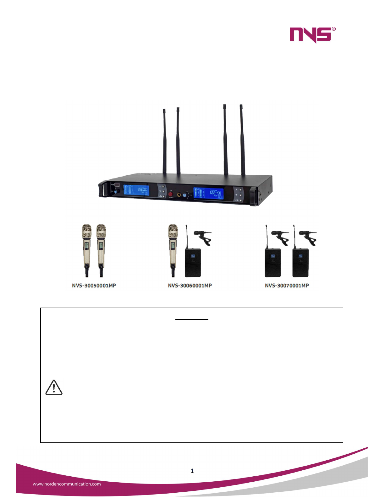
NVS-30050001MP/NVS-30060001MP
/NVS-30070001MP
Wireless Microphone Set
User Manual
1
Thank you for using our public address system. Please read this User Manual carefully
to make better use of this equipment
Attention
This equipment is not waterproof. To prevent fire or electric shock, please do
not place any liquid filled containers (such as vases or flowerpots) near the
equipment or expose the equipment to dripping, splashes, rain, or moisture.
Please hold the plug when moving the power cord. Do not pull the power cord
when pulling out the power plug. Do not touch the power cord when your hands
the device, please be sure to place it on a horizontal and stable surface.
Please keep this User Manual in good custody for future use.
2
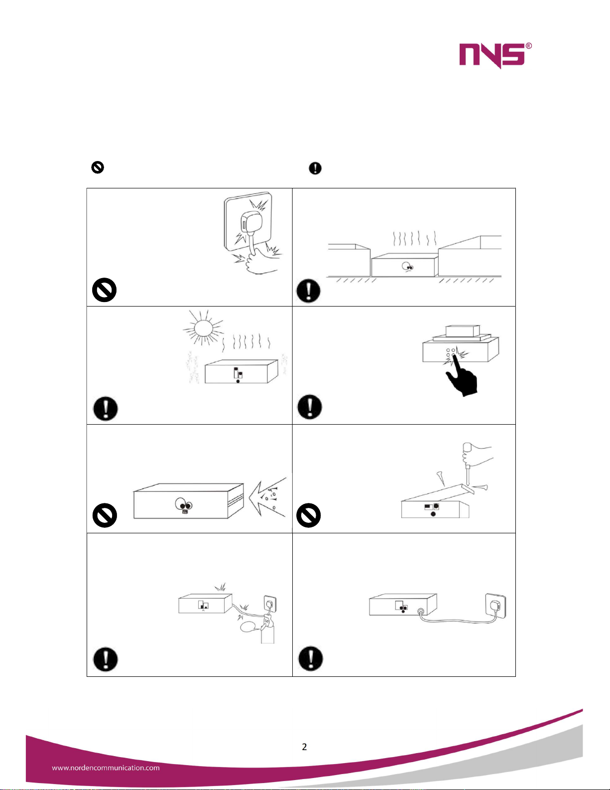
To assure the finest performance, please use or operate the product in accordance with
corresponding instructions.
This symbol indicates "forbidden content" This symbol indicates "compulsory Content”
Please make sure that the
power wire is NOT damaged.
Do NOT unplug the equipment
by pulling the power wire;
otherwise, it may cause electric
shock, short circuit or fire
When the equipment is in use, DO NOT block the air
outlet which should be kept clear, in order to avoid
overheat.
Do NOT store this
equipment in any
place with heavy
dust or vibration, or
where it is
extremely
cold or hot.
Please do NOT place any heavy article on this
equipment. Please operate
switches, buttons or
external audio source
carefully.
Please prevent foreign matters (such as paper,
metal etc.) entering the equipment through the
gaps or opening, in such cases, please cut off the
power supply immediately.
Do NOT
attempt to remove any internal component
from the equipment,
or to modify the
equipment in
whatever manner
In case that sound is suddenly off or there is
abnormal odor or smoke, please unplug the
equipment from the power socket to avoid
potential electric shock, fire or other accident.
The equipment
should be
inspected by
professional
personnel.
Burning smell
If the equipment is not in use for a long period,
please
unplug it from the AC power socket to realize zero
energy consumption.

3
Contents
Ambient Factors…….............................................................................................4
1. Product Specifications.....................................................................................5
1.1 System Parameters.............................................................................5
1.2 Receiver Index....................................................................................5
1.3 Transmitter Index...............................................................................6
2. Receiver Function...........................................................................................6
3. Receiver Instructions......................................................................................7
4. Receiver System Settings...............................................................................9
4.1 Channel/Frequency Settings..............................................................9
4.2 Frequency Pairing..............................................................................9
5. Transmitter Function.....................................................................................10
6. Transmitter Instructions................................................................................11
6.1 Portable Transmitter Function..........................................................13
6.2 Battery Replacement........................................................................14
6.3 Portable Transmitter.........................................................................14
6.4 Use with Headset Microphone.........................................................15
6.5 Use with Collar Microphone.............................................................16
6.6 Directional Antenna and Antenna Distributor..................................16
7. System Installation........................................................................................18
8. Common Failures and Solutions....................................................................20

4
Ambient Factors
This NVS product adopts radio frequency transmission and is susceptible to
outside wireless signals interference. Our all products are qualified products which
passed strict testing. If instantaneous frequency-loss occurred in the installation and
application, in most cases, the system frequency of the product is affected by the
interference of the external ambience. If it happens, please carefully check the
interference of external and internal installation ambient factors listed below and
make appropriate settings and adjustment on ambient and system.
1. Whether there is television tower, large cell phone launch base station or other
strong jamming signals around the site.
2. Whether there is a mobile phone signal amplifier installed in the site.
3. Whether high frequency wireless intercom system is used in the site, and other
brands of wireless microphone systems is installed.
4. Whether there are other metal objects that may block or attenuate wireless
signals around the system.
5. Whether the receiver antenna is too close to the computer, the computer or
other radio frequency interference machine.
6. Whether there is an obvious obstacle between the receiver and the transmitter.
7. Whether the surrounding environment is too humid.
CAUTION
When you encounter the above situations, please adjust the system reception signal by
improving the internal ambient and adjusting the host frequency receiving or call local
authorized agents for technical support.

5
1.Product Specifications
1.1 System Parameters
Model
NVS
-
30050001MP/
NVS
-
300
6
0001MP/
NVS
-
300
7
0001MP
Working frequency
640
-
690MHz
Modulation Broadband
FM
Number of channels 200
Channel interval 250KHz
Frequency stability Within ±0.005%
Dynamic range 100dB
Frequency response 50Hz
~
19KHz (±3dB) (The frequency of the entire system depends on
the microphone unit)
Comprehensive SNR >105dB
Composite distortion 0.5% @1000Hz
Working distance
1. About 200 meters.
2. If the use space or the electromagnetic field environment is
complicated, the working distance will be shortened. (The working
distance depends on many variables, including absorption, reflection,
and interference of RF signals.)
Working temperature -10
℃
~
+50
℃
Package size (mm) 590×320×115
Gross weight 5kg
1.2 Receiver Index
Receiver mode Double conversion superheterodyne
Mid-range frequency 110MHz, 10.7MHz
Antenna access BNC/50Ω
Sensitivity 12dBμV (80dB S/N)
Spurious suppression ≥75dB
Audio output level:
balanced
output
+10 dB (XLR)
Audio
output
level:
unbalanced
output
+4 dB(¼’’, 6.3mm Jack socket)
Power supply mode DC12V~13.5V / 500mA~2000mA input
Spurious suppression >75dB
Audio output 200mV
Output impedance XLR: 200Ω ¼’’ : 1KΩ
Distortion <0.1%
Function display
LCD
Machine size
484×210×44mm
Net weight
1.95kg

6
1.3 Transmitter Index
Microphone
Dynamic Microphone
Antenna
Handheld microphone with a spiral antenna, wearable transmitter
with ¼ wavelength whip antenna
Output power
High power 20
mW
,
Low power 7mW
Transition power 10mV
Spurious suppression
>50dB
Power
supply
2
AA
1.5V
alkaline
batteries
Battery
service
life
9
hours
at
20mW,
13
hours
at
7mW
Function
display
LCD
Net
weight
0.45kg
2. Receiver Functions

7
1. LCD display (Display frequency, channel, squelch, and electrical level, etc.)
2. Volume control
3. Infrared frequency pairing point (Coordinate with the "SYNC" button to transfer the
channel parameters to the transmitter)
4. UP (▲) 5. DOWN (▼) 6. SYNC
Press the “▲”“▼” and you can change or select frequency and Press “SYNC” to
confirm.
7. Power switch (When the power switch opens, the LCD is on. Press the power for 3
seconds and the receiver power will be off)
8. AF output (Mix two signals together to output)
9. DC power socket (12-18V DC power input stocket. The center electrode of the
socket is connected to the positive voltage)
10/11. AF output (XLR interface, signal of two channels are output respectively)
12. 10 radio frequency display: displays the received radio frequency state
13. 10 audio level display: Display audio signal state
14. Frequency menu display
:
Display current working frequency
3.Receiver Instructions
1. Power output connection
Connect the port of AC/DC to the DC input socket of the receiver's rear panel, connect
the other port to AC output socket.
2. Audio output connection
Connect one port of AF output line to the AF output port of the panel at the back of
the receiver; Connect the other port to the input jack of the mixer or amplifier; with
balanced XLR output and unbalanced 6.3 mm output. Please choose correctly
according to the situations.
3. Turn off the transmitter before turning on the receiver, and turn the receiver volume
down to the minimum.

8
4. Observe radio frequency (RF) and audio frequency (AF) signals in level display, if the
interference is greater, the channel should be switched to avoid interference points,
can also increase the squelch level to enhance the anti-interference ability.
5. Then turn on the transmitter power, and after pairing the channel well, the level
meter should display the radio frequency (RF) signal, adjust the receiver volume to the
appropriate level and speak to microphone, then the audio (AF) signal of the receiver
level would change according to the volume under normal condition. If there is no
sound output and no change in the level meter, it indicate that the system is not
working properly and must be repaired
6. Please unplug the receiver and remove the battery from the transmitter to avoid
damage if it isn’t used for a long time.
7. Use the most advanced Auto Scan feature to automatically search and fast lock
undisturbed working channels. This automatically selects the clean frequency point in
the environment, thus avoiding the entry of interference signal and realizing fast and
accurate automatic locking of the launch and reception channel.
8. Automatic selection setting and frequency matching operation method.
1. Press“▲”“▼” to choose frequency. Press SYNC on the left and the screen
will show IR=====flash. It will stop after a few seconds and display the current
working frequency.
2. Turn on the power switch on microphone handheld, and align the frequency
point (the display) of microphone positively to Red SYNC frequency point at the
upper left corner of the receiver to automatically match frequency.
Stay for 5 seconds, and infrared data will transmit receiver channel parameters to the
transmitter. After the frequency matching is completed, the display RF will appear 10
black signal frame. The MUTE mark disappears at the same time when the setting is
successful. The SYNC key on the right corresponds to the display on the right, and the
operation method is as described above. If there is no black signal frame or Mute mark
is still in, it is indicated that the frequency matching fails and receiver cannot work.

9
4. Receiver System Settings
Note
:
All functions should be confirmed by the "SET" button after the change of selection,
otherwise the LCD screen will continuously blink for reminding.
4.1 Channel/Frequency Settings
Press “ or ” to change the channel and frequency parameters
4.2 Frequency Pairing
Method is the same as item 8 of the receiver usage method.

10
5.Transmitter Function
1. LCD display (display group, channels and battery power)
2. Infrared frequency pairing point
:
Cooperate with the receiver "SET" button to
transmit the channel parameters to the transmitter.
3. Up (to set volume, switch between high and low power, and lock switch)
4. Down (to set volume, switch between high and low power, and lock switch)
5. Menu (could adjust volume VOLO4, PA reception enhancement, LOCK to lock three
function interfaces and use Up and Down to adjust parameters of current function.)
6. Light touch power switch (in the state of shutdown, hold down for 3 seconds to
boot; in the boot state, hold down for 3 seconds for shutdown)
7. Battery Card Spring button (Press the buttons on both sides at the same time by
your left hand, and pull the bottom of the microphone slightly hard in the right
hand. The battery could be pull out. )
11
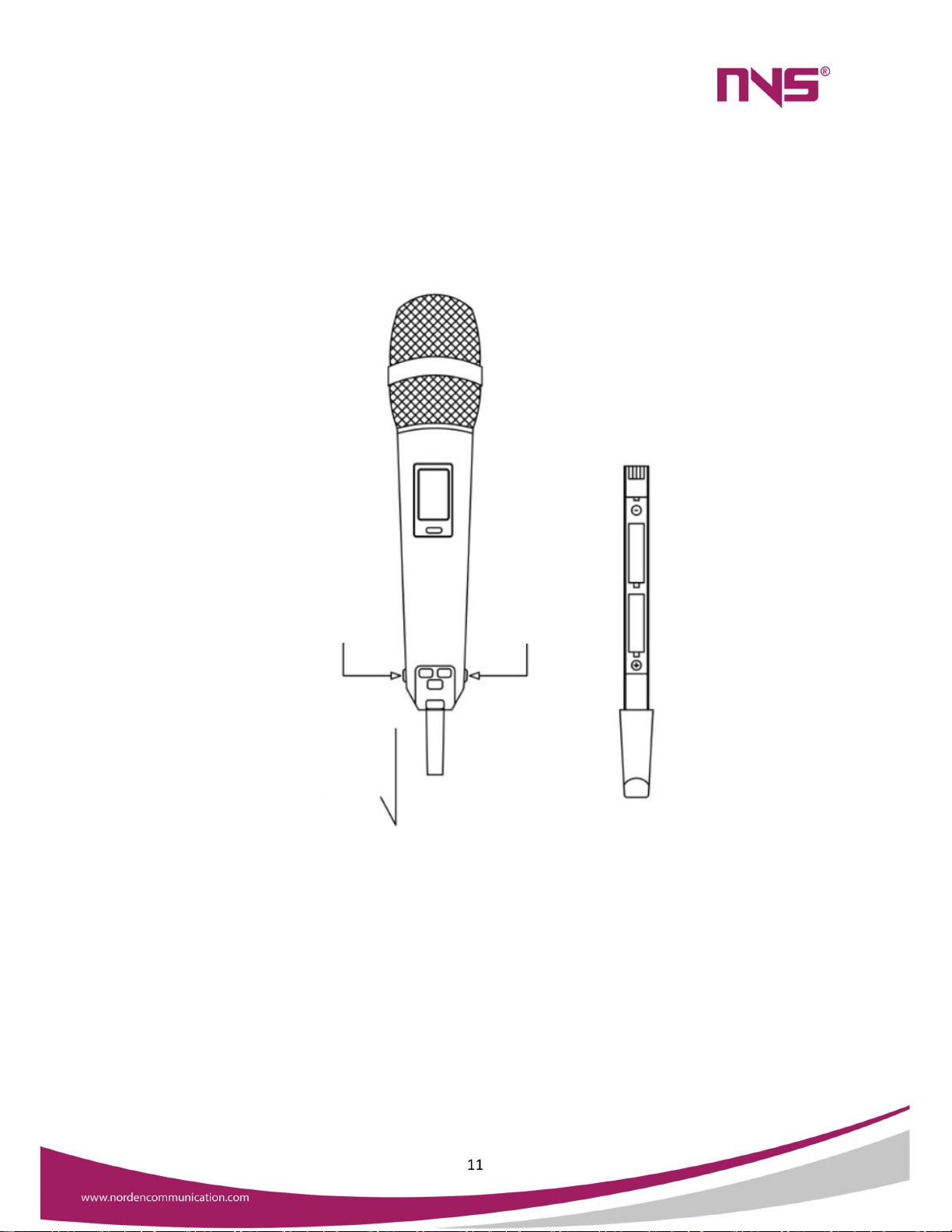
6. Transmitter Instructions
1. Pull the transmitter's battery compartment out as shown in Figure 1 below (Method
refers to transmitter function introduction item 6). Insert two AA (1.5V) battery into it
and put battery compartment into microphone.
Figure 1
2. Power switch: when power off, press it on. When power on, press it and hold for 3
seconds to turn off.
3. To prevent the sound of the boot, the Mute function shuts down automatically 3
seconds after booting.
Press
and Hold
Press and Hold
Pull Down to remove
the battery Holder

12
Figure 2
4. Volume adjustment: press menu key and display will show “VOLO1” as shown in
Figure 2. Figure 3 is the current volume. Press Up to turn up volume and Down to turn
down volume. Adjustment range is VOLO1-VOLO8.
Figure 3
5. Transmitter power settings: press the menu key continuously. “PA H/L” shown on
the display is the current power. Press Up and Down to switch between high (H) and
low (L) power. Under high power, transmission signal is strong and under low power,
transmission signal is weak. (as shown in Figure 4)
Figure 4
6. Lock function adjustment: press the menu key continuously until “LOCK” is shown
on the display. Press Up and Down to turn on and turn off lock function. When there
is “ ” on the display, all functions are locked and cannot be adjusted.
4 is the volume value,
with the range of 0-8
13
Figure 5
7. Turn off transmitter after using. If you do not use it for a long time, remove the
transmitter's battery in case of damage.
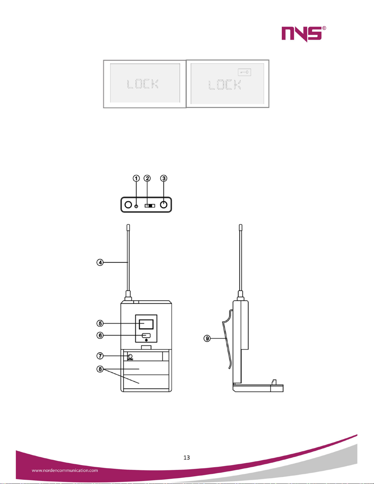
6.1 Portable Transmitter Function
1. Status indicator (When the power switch is placed on the "on", the indicator light
shines, indicating that the battery is normal. If it does not shine, the battery is not

14
powered or installed. If the light is always on, it means that the battery is running out
of power and must be replaced)
2. Gain Control
3. MIC input
4. Antenna (1/4 wave length whip antenna)
5. LCD display.(Show current working channel and battery power)
6. Power switch
7. Infrared frequency pairing (Cooperate with the receiver "SET" button to transmit
the channel parameters to the transmitter.)
8. Battery holder
9. Waist clip (used to hold the mini microphone to belt.)
6.2 Battery Replacement
1. The battery holder is in front of the transmitter.
2. Hold down the 2 ends and it will open.
3. Insert two batteries and notice the correct electrode.
4. Insert to the right place.
6.3 Portable Transmitter
1. Insert two 1.5V batteries into the battery rack.
2. Push the power switch to the open position.
3. Frequency pairing: match the receiver "SYNC" key to transmit the channel
parameters to the transmitter Channel Display Mode
Channel Display Mode
15
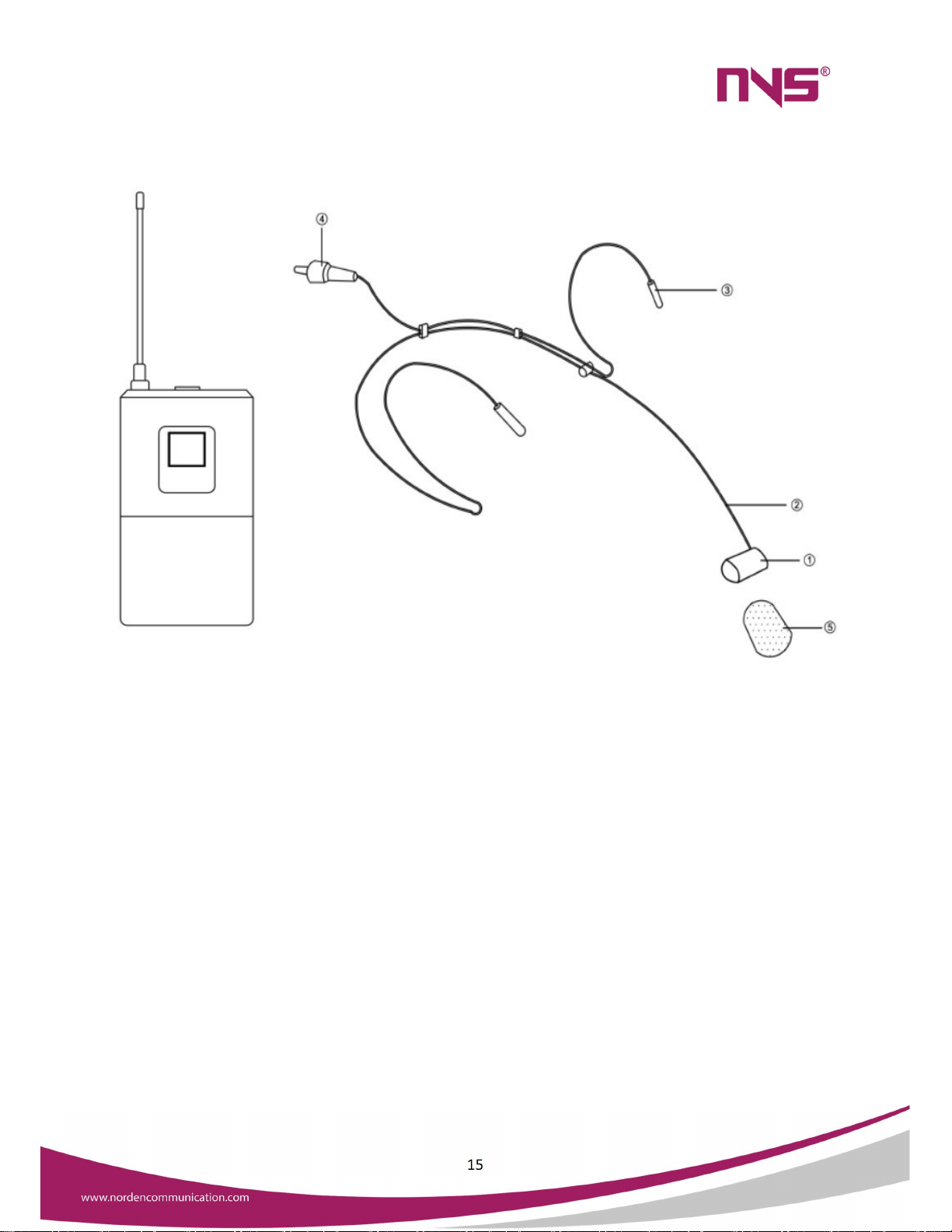
6.4 Use with Headset Microphone
1. Microphone
2. Hose
3. Neck rack
4. Mini XLR
5. Windproof sponge
Hang the headset microphone on the ears from the back of the head and raises the
rack to match the sound source.
It is about 1.5 to 2 inches away from the mouth. Insert the small XLR and place the
MIC line into the "MIC in"hole of the carry-on transmitter.

16
6.5 Use with Collar Microphone
1. Mini XLR Plug
2. Clip
3. Microphone
4. Windproof sponge
Hang on clothes, ties, lapel and other position which is suitable for picking up the sound.
Insert the small XLR and place the MIC line into the "MIC in" hole of the carry-on
transmitter.
6.6 Directional Antenna and Antenna Distributor
1. The use of directional antennas with antenna distributor mainly increases the receiving
distance. 1 antenna distributor can be used with 4 receivers at the same time (as shown
in connection mode 1).

17
2. If you only need to increase receiving distance of 1 machine, the directional antenna
can be connected directly to the "ANT A" and "ANT B" ends of the receiver (as shown in
connection mode 2). However, the receiving distance in this way is less than that of
combined use of directional antenna and antenna distributor.
3. Directional antenna needs to be aligned to the direction of the microphone
4. Antenna distributor can supply power for each receiver host.
Method 1: 1 antenna distributor can be used for 4 non-true diversity receivers or 2 true
diversity receivers at the same time.
Method 1

18
Method 2: Use directional antenna with receiver.
Method 2
7. System Installation
Installation note
Before installing this system, please read the guidelines of "Ambient factors" to
preclude the external and internal interference signal source which may influence the
effect of wireless signal receiving.

19
Placing requirements
1. To ensure that the system is in optimum working condition and reduce the reflected
dead angle, the receiver should be placed at least one meter away from the ground,
the surrounding walls, and metal surfaces. (Please see the picture)
2. The transmitter and receiver should be kept at a proper distance, preferably at least
two meters
3 Try to reduce the obstacles between transmitter and receiver.
4. When multiple receivers are used at the same time, the frequency of the receiver
should be kept in reasonable space, preferably at a frequency interval of 10MHz.
5. This antenna is put into the two antenna plug in the back of the receiver, and placed
in "L" vertical angle for best reception state, other state of any Angle and screw down
the mast is would abate signal receiving, any other angles and the screw down the
antennas will weaken the signal reception.
6. Connect the power adapter to the receiver's power input socket (The power adapter
adapts to the working voltage automatically
This manual suits for next models
2
Table of contents


