Nordmann Engineering ES4 How to use

SHORT FORM INSTRUCTIONS
Steam air humidier
Nordmann ES4
2559454-A EN 1806

Thank you for choosing Nordmann
Installation date (MM/DD/YYYY):
Commissioning date (MM/DD/YYYY):
Site:
Model:
Serial number:
Proprietary Notice
This document and the information disclosed herein are proprietary data of Nordmann Engineering AG. Neither
this document, nor the information contained herein shall be reproduced, used, or disclosed to others without the
written authorisation of Nordmann Engineering AG, except to the extent required for installation or maintenance
of recipient's equipment.
Liability Notice
Nordmann Engineering AG does not accept any liability due to incorrect installation or operation of the equipment
or due to the use of parts/components/equipment that are not authorised by Nordmann Engineering AG.
Copyright Notice
© Nordmann Engineering AG, All rights reserved.
Technical modications reserved.

3
Contents
1 Introduction 4
2 Product Overview 5
2.1 Models overview 5
2.2 Identicationoftheunit 6
2.3 Steamhumidierconstruction 7
2.4 Humidicationsystemoverview 8
3 Installation overviews 10
4 Wiring diagram/Current data 12
4.1 WiringdiagramNordmannES4 12
4.2 Currentdata 13
5 Productspecications 14
5.1 Technicaldata 14
5.2 Unitdimensions 15

4
1 Introduction
The present short form instructions are a summary of the most important
information from the installation and operating instructions of the Nord-
mann ES4.
The present short form instructions do not replace the installation and
operating instructions of the Nordmann ES4. In either case the installation
and operating instructions of the Nordmann ES4 must be read before car-
rying out any work on the Nordmann ES4 and the information and safety
instructions in it must be followed and upheld.

5
2 Product Overview
2.1 Models overview
Steam air humidiers Nordmann ES4 are available with different heating
voltages and steam capacities ranging from 5 kg/h up to a max. of
65 kg/h.
Heating voltage ** Max. steam capacity
in kg/h
Model
Nordmann ES4
Unit size
Unit small Unit large
400V3
(400 V/3~/50...60 Hz)
5 534 1
8 834 1
15 1534 1
23 2364 1
32 3264 1
45 4564 1
65 6564 1
400V2
(400 V/2~/50...60 Hz)
5 524 1
8 824 1
230V3
(230 V/3~/50...60 Hz)
5 532 1
8 832 1
15 1532 1
23 2362 1
32 3262 1
230V1
(230 V/1~/50...60 Hz)
5 522 1
8 822 1
** Other heating voltages on request
Key model designation
Example:
Nordmann ES4 4564 400V3
Product designation:
Unit model:
Heating voltage:
400V/3~/50...60Hz: 400V3
400V/2~/50...60Hz: 400V2
230V/3~/50...60Hz: 230V3
230V/1~/50...60Hz: 230V1

6
2.2 Identicationoftheunit
The identication of the unit is found on the type plate:
Nordmann Engineering AG, Talstrasse 35-37, 8808 Pfäfkon SZ, Switzerland
Type: ES4 4564 Ser.Nr.: XXXXXXX 02.10
Heating voltage: 400V / 3~ / 50...60Hz Power: 33.8 kW
Steam capacity: 45.0 kg/h Ctrl. Voltage: 230V / 1~ / 50...60Hz
Water pressure: 1...10 bar
Engineered in Switzerland, Made in Germany
Type designation Serial number (7 digits) Month/Year
Heating voltage
Maximum steam capacity per unit
Admissible water supply pressure
Power consumption
Control voltage
Field with certication symbols

7
2.3 Steamhumidierconstruction
1 Housing (small, large)
2 Cable openings, top side
3 SC pump (option)
4 Main contactor
5 Power board
6 Terminals heating voltage (option)
7 Remote operating and fault
indication board (option)
8 Control board with ES4 Card
9 Power supply unit 24 V (option)
10 Drain/info key
11 Operation status indicators
12 Unit switch
13 Water cup
14 Filling hose
15 Water supply hose
16 Overow hose
17 Drain valve
18 Inlet valve
19 Water supply connector
20 Drain connector
21 Cable openings, bottom side
22 Type plate
23 Steam cylinder
24 Level sensor
25 Electrode plug
26 Steam outlet
gure shows small unit
3
2
1
4
5
6
7
9
12
11
10
8
19
20
21
23
24
25
26
22
13
15
18
17
14
16
8
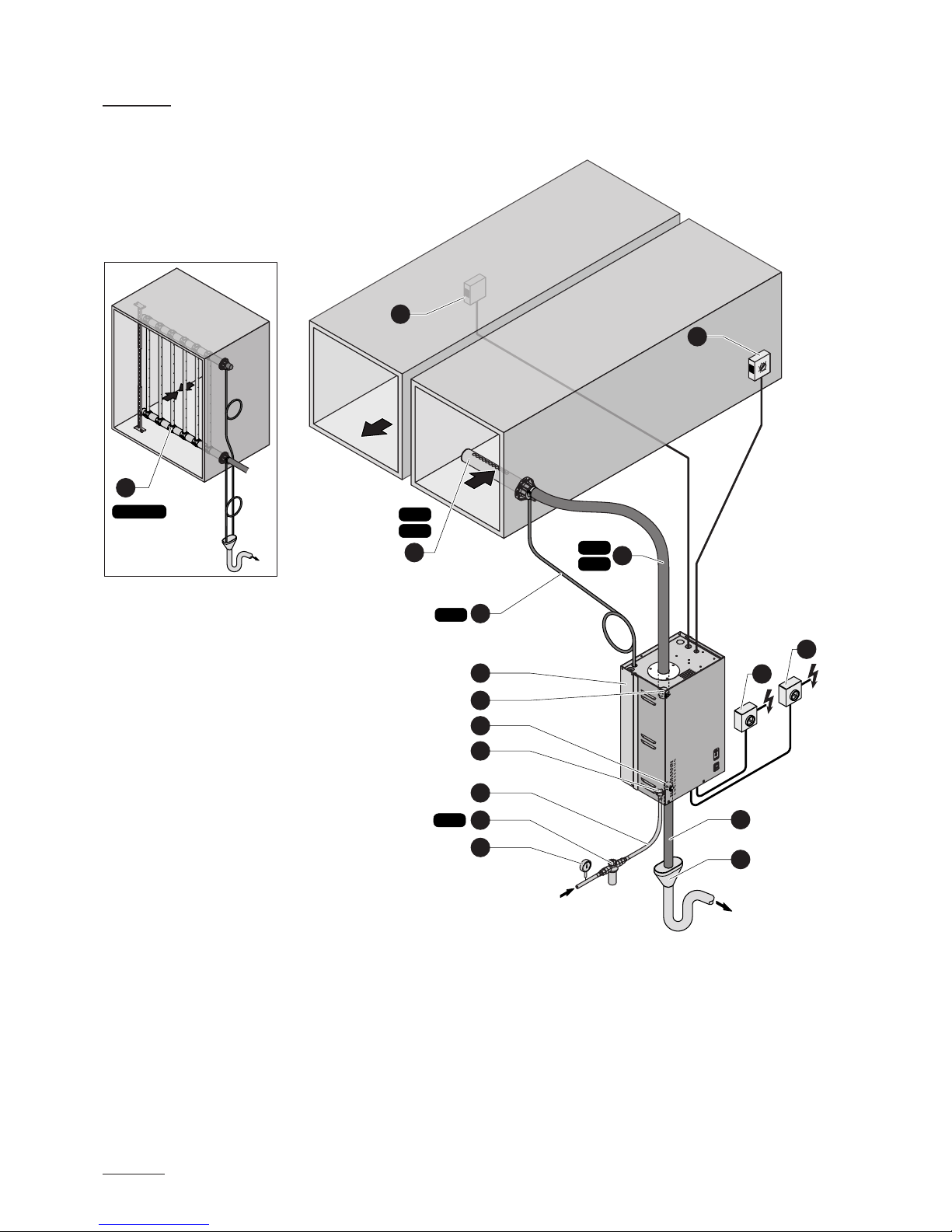
2.4 Humidicationsystemoverview
System overview duct humidication
1 Steam humidier
2 Steam connector
3 Water drain connector
4 Water supply connector
5 Water connection hose G 3/4"- G 3/8"
(included in the delivery)
6 Filter valve (accessory “Z261”)
7 Manometer (installation recommended)
8 Funnel with siphon (building side)
9 Water drain hose (included in the delivery)
10 Service switch control voltage supply (building side)
11 Service switch heating voltage supply (building side)
12 Steam hose (accessory “DS..”)
13 Condensate hose (accessory “KS10”)
14 Steam distribution pipe (accessory “DV41-
..”/“DV71-..”)
15 Steam distribution system (accessory “MultiPipe”)
16 Humidity controller 0-10V or Humidistat
17 Safety humidistat
125...1250 µS/cm
1...10 bar
1...40 °C
16
15
ONOFF
1
2
3
4
5
6
7
DS35
DS22
Z261
ONOFF
12
13
17
KS10
11
10
14
DV41
DV71
MultiPipe
8
9
9
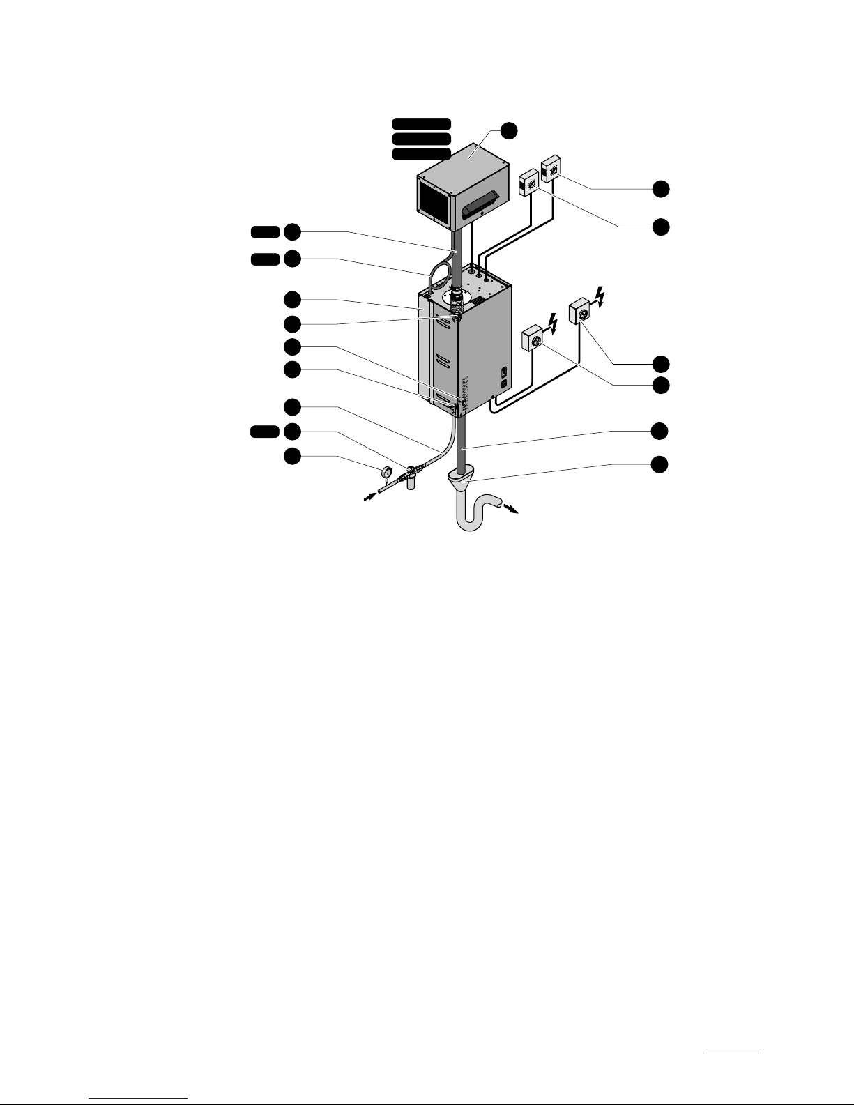
System overview room humidication
125...1250 µS/cm
1...10 bar
1...40 °C
1 Steam humidier
2 Steam connector
3 Water drain connector
4 Water supply connector
5 Water connection hose G 3/4"- G 3/8"
(included in the delivery)
6 Filter valve (accessory “Z261”)
7 Manometer (installation recommended)
8 Funnel with siphon (building side)
9 Water drain hose (included in the delivery)
10 Service switch control voltage supply (building side)
11 Service switch heating voltage supply (building side)
12 Steam hose (accessory “DS..”)
13 Condensate hose (accessory “KS10”)
14 Ventilation unit (accessory “FAN4 N...”)
15 Humidity controller 0-10V or Humidistat
16 Safety humidistat
ONOFF
ONOFF
10
11
15
16
1
3
4
5
6
7
Z261
DS80
KS10 13
12
FAN4 N S W
FAN4 N M W
FAN4 N L W
2
8
9
14

10
Control voltage
Heating voltage
On/Off-ControlContinuous control 0-10V
External safety chain
3 Installation overviews
Installation overview duct humidication
X3
L1 NSC1SC2
B3
max.
ES4
ekt.
CONT.SIGN
V+ IN GND
X1
+ –
0-10V
A1
CONT.SIGN
V+ IN GND
X1
On/Off
A2
On/Off Mode
JP1
On/Off Mode
JP1
ES4
ext.
ES4
ext.
Q3
230V/1
~/
50...60Hz
L1 N
F3
X3
L1 NSC1SC2
ES4
ext.
L1
Q2
K1
X0
F2
L1 L2 L3
L1 L2 L3
L1 L2 L3
400 V/3~/50..60 Hz
230 V/3~/50..60 Hz
Q2
F2
L1 N PE
PE
PE
230 V/1~/50..60 Hz
Q2
F2
L1 L2
400 V/2~/50..60 Hz
PE
ES4
ext.
≥ 40 mm
min. 50 cm
ONOFF
DS35
DS22
Z261
ONOFF
125...1250 µS/cm
1...10 bar
1...40 °C
ø14/7 mm
G 3/4"
G 1/2"
G 3/8"
Q2
Q3
B3
DV41
DV71
Pmin
1500 Pa
-800 Pa
Pmax
Rmin. 300 mm
Ømin.
200 mm
min. 300 mm
min. 300 mm
min. 20 %
–
KS10
min. 5 %–
min. 20 %
+
A1 / A2
ø 30 mm

11
Installation overview room humidication
Control voltage
Heating voltage
On/Off-ControlContinuous control 0-10V
External safety chain
X3
L1 NSC1SC2
B3
max.
ES4
ext.
CONT.SIGN
V+ IN GND
X1
+ –
0-10V
A1
CONT.SIGN
V+ IN GND
X1
On/Off
A2
On/Off Mode
JP1
On/Off Mode
JP1
ES4
ext.
ES4
ext.
L1
Q2
K1
X0
F2
L1 L2 L3
L1 L2 L3
L1 L2 L3
400 V/3~/50..60 Hz
230 V/3~/50..60 Hz
Q2
F2
L1 N PE
PE
PE
230 V/1~/50..60 Hz
Q2
F2
L1 L2
400 V/2~/50..60 Hz
PE
ES4
ext.
X3
L1 NSC1SC2
ES4
ext.
Q3
L1 N
F3
FAN4 N...
L1 N
ONOFF
ONOFF
FAN4 N S W
FAN4 N M W
FAN4 N L W
Q2
Q3
Z261
125...1250 µS/cm
1...10 bar
1...40 °C
ø14/7 mm
≥ 40 mm
G 3/4"
G 1/2"
G 3/8"
min. 50 cm
Ømin.
100 mm
A1 / A2
B3
ø 30 mm
DS80
KS10

12
4.1 Wiring diagram Nordmann ES4
A1 Continuous controller (active 0-10V)
A2 On/Off controller (passive 24VDC), set jumper on JP1
A3 On/Off control (active 230VAC)
B1 Ventilation interlock
B2 Airow monitor
B3 Safety humidistat
F1 Internal fuse power board (6.3 A, slow acting)
F2 External fuse heating voltage supply
F3 External fuse control voltage supply
F4 External fuse 230V On/Off control
H1 Remote operating and fault indication (option “RFI”)
J Short circuited, if no external monitoring devices are connected
JP1 Jumper On/Off mode
K External safety chain (230V/5A)
K1 Main contactor (for connecting the heating voltage supply to the unit)
M Fan unit FAN4.../Turbo...
Q2 External service switch heating voltage supply
Q3 External service switch control voltage supply
S1 Rotary switch "Cylinder type”
S2 Potentiometer “Drain factor”
S3 Potentiometer “Power limitation”
S4 DIP switch “General unit settings”
X0 Connection terminal heating voltage (option THV)
X1 Connection terminal control signal
X2 Connection terminal On/Off control active
X3 Connection terminal control voltage
Control board Power board
ES4 Card
red yellow green
F1
(6.3 AT)
CONT.SIGN
V+ IN GND
X2 X3
VD
MAIN SUPPLY
L1 NSC1SC2
LEV.SENSOR
Driver board
CPU board
J1
X1
CURRENT SENSOR
CPU BOARD
1 2
On/Off
JP1 must be plugged
B3
K
B2
B1
J
Q3
230 V/1~/50..60 Hz
L1 N
F3
On/Off Mode
JP1
+ –
0-10V
A1
H1
A2
A3
F4
230V
L1’
1 2 3 4 5 6 7 8 9 10
Error Service Steam Unit On
Cylinder
Drain Factor
Power Limit
Manual Drain
Low Conduct.
Standby Drain
Force Drain
Cylinder A/D
GFCI-Mode
Offset
Settings
0
DriverRFI
ON
1 2 3 4 5 6
J8
J1
V+ IN GND
X5
X7
X8
X4
1 2 3 4
SWITCH
1 2 3 4
INLET
1 2
CONTACTORDRAIN
∆p
max.
M
L1 N
PE
S1
S2
S3
S4
L1
Q2
K1
X0
F2
L1 L2 L3
L1 L2 L3
L1 L2 L3
400 V/3~/50..60 Hz
230 V/3~/50..60 Hz
Q2
F2
L1 N PE
PE
PE
230 V/1~/50..60 Hz
Q2
F2
L1 L2
400 V/2~/50..60 Hz
PE
ES4
ext.
4 Wiring diagram/Current data

13
4.2 Current data
Heating voltage Max. steam
capacity
[kg/h]
Nordmann
ES4 ..
Nominal power
[kW]
Nominal
current
[A]
Main fuses F2
[A]
400V3
(400 V/3~/50...60 Hz)
5 534 3.8 5.4 3x 10
8 834 6.0 8.7 3x 16
15 1534 11.3 16.2 3x 20
23 2364 17.3 24.9 3x 35
32 3264 24.0 34.6 3x 50
45 4564 33.8 48.7 3x 63
65 6564 48.8 70.4 3x 100
400V2
(400 V/2~/50...60 Hz)
5 524 3.8 9.4 2x 16
8 824 6.0 15.1 2x 20
230V3
(230 V/3~/50...60 Hz)
5 532 3.8 9.4 3x 16
8 832 6.0 15.1 3x 20
15 1532 11.3 28.2 3x 35
23 2362 17.3 43.3 3x 63
32 3262 24.0 60.2 3x 80
230V1
(230V/1~/50...60Hz)
5 522 3.8 16.3 25
8 822 6.0 26.1 35
14
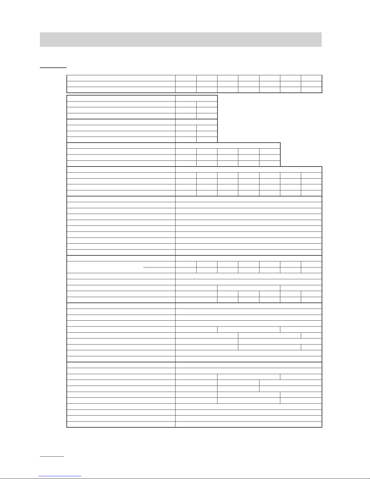
5 Productspecications
5.1 Technicaldata
Steam capacity in kg/h 5 8 15 23 32 45 65
Capacity range in kg/h 1...5 1.6...8 3...15 4,6...23 6,4...32 9...45 13...65
Nominal power in kW 3,8 6,0 11,3 17,3 24,0 33,8 48,8
Heating voltage 230V/1~/50..60Hz *
Unit model 522 822
Nominal current in A 16,3 26,1
Steam cylinder type ** 522A 822A
Heating voltage 400V/2~/50..60Hz *
Unit model 524 824
Nominal current in A 9,4 15,0
Steam cylinder type ** 524A 824A
Heating voltage 230V/3~/50..60Hz *
Unit model 532 832 1532 2362 3262
Nominal current in A 9,4 15,1 28,2 43,3 60,2
Steam cylinder type ** 532A 832A 1532A 2362A 3262A
Heating voltage 400V/3~/50..60Hz *
Unit model 534 834 1534 2364 3264 4564 6564
Nominal current in A 5,4 8,7 16,2 24,9 34,6 48,7 70,4
Steam cylinder type ** 534A 834A 1534A 2364A 3264A 4564A 6564A
Steam cylinder type *** 534A-L 834A-L 1534A-L 2364A-L 3264A-L 4564A-L ---
Control voltage 1 x 230V / 50-60 Hz
Operating conditions
Admissible water pressure 1...10 bar
Water quality Untreated drinking water with a conductivity of 125...1250 µS/cm
Admissible water temperature 1...40 °C
Admissible ambient temperature 1...40 °C
Admissible ambient humidity max. 75% rh (non condensing)
Admissible duct air pressure -0.8 kPa...1.5 kPa; overpressure kit (option) up to 10.0 kPa
Type of protection IP 20
Conformity CE, VDE, GOST
Dimensions/Weights
Housing (WxHxD) in mm 377x612x279 1 1 1
492x670x351 1 1 1 1
Water supply connector G 3/4" (outside thread)
Water drain connector ø 30 mm
Steam connector 1 x ø 22 mm 1 x ø 35 mm 2 x ø 35 mm
Net weight in kg 19 19 28 28 28 28
Operating weight in kg 24 30 65 65 65 65
Options
Cable gland 1xCG
Overpressure set 1xOPS
Remote operating and fault indication 1xRFI
Steam hose connector with condensate trap 1xCT22 1xCT35 2xCT35
Internal control voltage supply 1xS-CVI 1xM-CVI 1xL-CVI
Transformer (400 V/230 V) 1xM-Trafo 1xL-Trafo
Terminals heating voltage 1xS-THV 1xM-THV 1xL-THV
SC pump 1xSC
24 VDC power supply 1x24VDC
Accessories
Filter valve Z261
Steam distribution pipe 1x DV41-... 1x DV71-... 2x DV71-...
Steam distribution system MultiPipe ––– 1xSystem 1 1xSystem 2
Fan unit 1xFAN4 N S W 1xFAN4 N M W 1xFAN4 N L W
Steam hose / meter 1xDS22 1xDS35 2xDS35
EcoTherm insulation hose 1xECT22 1xECT60 2xECT60
Condensate hose / meter KS10
Duct humidistat 1xHBC
Room humidistat 1xHSC
All-waether protective housing Layout according to the separate data sheet
* Other heating voltages on request
** Steam cylinder for water conductivity from 125 to 1250 µS/cm (standard version)
*** Steam cylinder for low water conductivity from 80 to 125 µS/cm

15
5.2 Unit dimensions
Nordmann ES4 5/8/15 (dimensions in mm)
187
127
176
65
ø30
377
61269
279
144
130
61
120 120
189
490

16
Nordmann ES4 23/32/45/65 (Dimensions in mm)
ø30
492
670
69
351 246
180 180
50
547
223
163
118
229
180
182


Nordmann Engineering AG
Lindenhofstrasse 28, 4052 Basel, Switzerland
Phone +41 61 404 46 50, Fax +41 61 404 46 79
www.nordmann-engineering.com,
CH94/0002.01
Table of contents
Other Nordmann Engineering Humidifier manuals

Nordmann Engineering
Nordmann Engineering Omega Pro User manual

Nordmann Engineering
Nordmann Engineering MinAir User manual

Nordmann Engineering
Nordmann Engineering AT4 Quick setup guide

Nordmann Engineering
Nordmann Engineering AT4 User manual

Nordmann Engineering
Nordmann Engineering Omega Pro Series User manual

Nordmann Engineering
Nordmann Engineering Omega Pro User manual

Nordmann Engineering
Nordmann Engineering AT4 User manual


