Nordson EFD 7362738 User manual

™
Safety Enclosure for Automated Dispensing
Systems
Operating Manual
Electronic pdf les of Nordson EFD
manuals are also available at
www.nordsonefd.com

Safety Enclosure for Automated Dispensing Systems
2www.nordsonefd.com [email protected] 800-556-3484 Sales and service of Nordson EFD dispensing systems are available worldwide.
You have selected a reliable, high-quality dispensing system safety enclosure from Nordson EFD, the
world leader in uid dispensing. Nordson EFD automated dispensing systems are designed specically
for industrial dispensing and will provide you with years of trouble-free, productive service.
This manual will help you maximize the usefulness of your automated dispensing system safety
enclosure.
Please spend a few minutes to become familiar with the controls and features. Follow our recommended
testing procedures. Review the helpful information we have included, which is based on more than
50years of industrial dispensing experience.
Most questions you will have are answered in this manual. However, if you need assistance, please do
not hesitate to contact EFD or your authorized EFD distributor. Detailed contact information is provided
on the last page of this document.
The Nordson EFD Pledge
Thank You!
You have just purchased the world’s nest precision dispensing equipment.
I want you to know that all of us at Nordson EFD value your business and will do everything in our power
to make you a satised customer.
If at any time you are not fully satised with our equipment or the support provided by your Nordson
EFD Product Application Specialist, please contact me personally at 800.556.3484 (US), 401.431.7000
I guarantee that we will resolve any problems to your satisfaction.
Thanks again for choosing Nordson EFD.
Srini Subramanian, General Manager
Srini Subramanian

3www.nordsonefd.com [email protected] 800-556-3484 Sales and service of Nordson EFD dispensing systems are available worldwide.
Safety Enclosure for Automated Dispensing Systems
Contents
Contents..........................................................................................................................................................................3
Introduction .....................................................................................................................................................................4
Nordson EFD Product Safety Statement ........................................................................................................................5
Halogenated Hydrocarbon Solvent Hazards ...............................................................................................................6
High Pressure Fluids....................................................................................................................................................6
Qualied Personnel......................................................................................................................................................6
Intended Use ...............................................................................................................................................................7
Regulations and Approvals..........................................................................................................................................7
Personal Safety............................................................................................................................................................7
Fire Safety....................................................................................................................................................................8
Preventive Maintenance ..............................................................................................................................................8
Important Disposable Component Safety Information ................................................................................................9
Action in the Event of a Malfunction............................................................................................................................9
Disposal .......................................................................................................................................................................9
Specications................................................................................................................................................................10
Operating Features........................................................................................................................................................10
Installation .....................................................................................................................................................................11
Unpack the System Components and Install the Feet ..............................................................................................11
(Vision Systems Only) Install the Monitor and Keyboard...........................................................................................11
Install the Robot in the Enclosure..............................................................................................................................12
Connect Cables .........................................................................................................................................................14
Install the Dispensing System and Reinstall the Panels ............................................................................................15
Connect Inputs / Outputs (Optional)..........................................................................................................................16
Initial Startup..............................................................................................................................................................17
Operation.......................................................................................................................................................................19
Starting the System ...................................................................................................................................................19
About the RUN/TEACH Switch..................................................................................................................................19
Running a Program....................................................................................................................................................20
Stopping the System (Emergency Stop)....................................................................................................................20
Resetting the System.................................................................................................................................................20
Service...........................................................................................................................................................................21
Part Numbers ................................................................................................................................................................21
Troubleshooting.............................................................................................................................................................22
Technical Data ...............................................................................................................................................................22
General Block Wiring Diagram (Standard and EU) ....................................................................................................22
Safety Enclosure I/O Terminal Block Pin Assignments..............................................................................................22

Safety Enclosure for Automated Dispensing Systems
4www.nordsonefd.com [email protected] 800-556-3484 Sales and service of Nordson EFD dispensing systems are available worldwide.
Introduction
This manual provides safety, installation, operation, service, and parts information for guarded safety
enclosures for all PROPlus, PRO, EV, E, and R Series automated dispensing systems. The safety
enclosure is shipped fully assembled in a large wooden crate, making installation and setup easy.
For installation in the European Union (EU) and areas with similar regulations, these CE-compliant
enclosures provide full compliance with EU Machinery Directive 2006/42/EC, essential for all production
requirements.
Nordson EFD safety enclosures easily integrate into existing production lines. Each enclosure features an
internal lockable electrical control box and integrated wireways that allow easy cable routing for faster,
safer setup. A safety light curtain at the front opening stops the dispensing cycle anytime an object
passes its sensing eld.
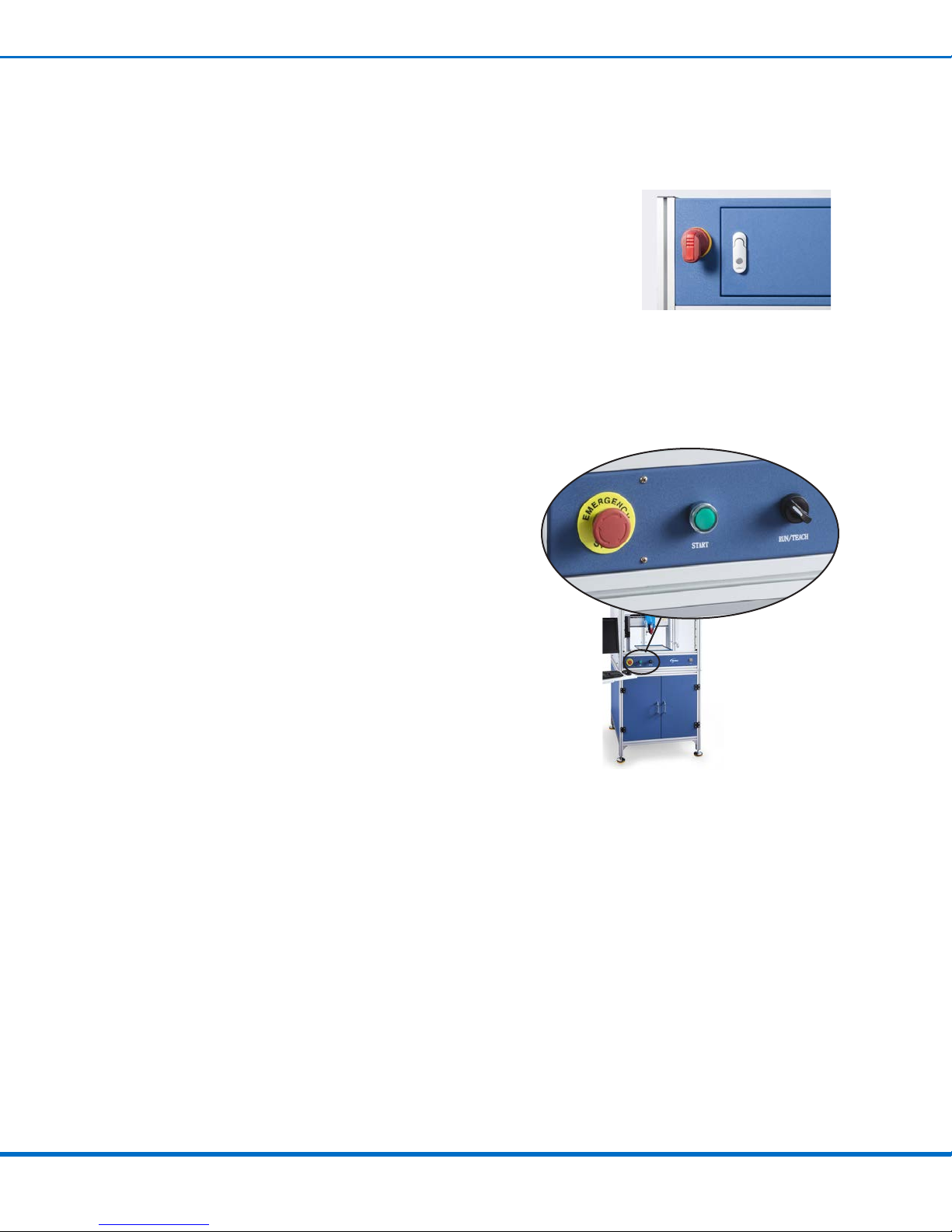
External controls, including START, EMERGENCY STOP, and RUN/TEACH, allow operators to control
the dispensing system from outside of the enclosure. An ergonomic, adjustable monitor bracket and
keyboard tray make it easy to program vision-guided systems at any height.
CE-compliant safety enclosure with an installed automated
dispensing system (EV Series system and standard safety
enclosure shown)
5www.nordsonefd.com [email protected] 800-556-3484 Sales and service of Nordson EFD dispensing systems are available worldwide.
Safety Enclosure for Automated Dispensing Systems
Nordson EFD Product Safety Statement
The safety messages that follow have a CAUTION level hazard.
Failure to comply may result in minor or moderate injury.
CAUTION
READ MANUAL
Read manual for proper use of this equipment. Follow all safety instructions. Task- and equipment-
specic warnings, cautions, and instructions are included in equipment documentation where
appropriate. Make sure these instructions and all other equipment documents are accessible to
persons operating or servicing equipment.
The safety message that follows has a WARNING level hazard.
Failure to comply could result in death or serious injury.
WARNING
ELECTRIC SHOCK
Risk of electric shock. Disconnect power before removing covers and / or disconnect, lock out, and
tag switches before servicing electrical equipment. If you receive even a slight electrical shock, shut
down all equipment immediately. Do not restart the equipment until the problem has been identied
and corrected.
MAXIMUM AIR PRESSURE
Unless otherwise noted in the product manual, the maximum air input pressure is 7.0 bar (100 psi).
Excessive air input pressure may damage the equipment. Air input pressure is intended to be applied
through an external air pressure regulator rated for 0 to 7.0 bar (0 to 100 psi).
RELEASE PRESSURE
Release hydraulic and pneumatic pressure before opening, adjusting, or servicing pressurized
systems or components.
BURNS
Hot surfaces! Avoid contact with the hot metal surfaces of heated components. If contact can not be
avoided, wear heat-protective gloves and clothing when working around heated equipment. Failure
to avoid contact with hot metal surfaces can result in personal injury.

Safety Enclosure for Automated Dispensing Systems
6www.nordsonefd.com [email protected] 800-556-3484 Sales and service of Nordson EFD dispensing systems are available worldwide.
Nordson EFD Product Safety Statement (continued)
Halogenated Hydrocarbon Solvent Hazards
Do not use halogenated hydrocarbon solvents in a pressurized system that contains aluminum components.
Under pressure, these solvents can react with aluminum and explode, causing injury, death, or property damage.
Halogenated hydrocarbon solvents contain one or more of the following elements.
Element Symbol Prefix
Fluorine F “Fluoro-”
Chlorine Cl “Chloro-”
Bromine Br “Bromo-”
Iodine I “Iodo-”
Check the Safety Data Sheet (SDS) or contact your material supplier for more information. If you must use
halogenated hydrocarbon solvents, contact your EFD representative for compatible EFD components.
High Pressure Fluids
High pressure uids, unless they are safely contained, are extremely hazardous. Always release uid pressure before
adjusting or servicing high pressure equipment. A jet of high pressure uid can cut like a knife and cause serious
bodily injury, amputation, or death. Fluids penetrating the skin can also cause toxic poisoning.
Any injury caused by high pressure liquid can be serious. If you are injured or even suspect an injury:
• Go to an emergency room immediately.
• Tell the doctor that you suspect an injection injury.
• Show the doctor the following note.
• Tell the doctor what kind of material you were dispensing.
WARNING
Medical Alert — Airless Spray Wounds: Note to Physician
Injection in the skin is a serious traumatic injury. It is important to treat the injury surgically as soon as possible. Do
not delay treatment to research toxicity. Toxicity is a concern with some exotic coatings injected directly into the
bloodstream.
Qualified Personnel
Equipment owners are responsible for making sure that EFD equipment is installed, operated, and serviced by
qualied personnel. Qualied personnel are those employees or contractors who are trained to safely perform
their assigned tasks. They are familiar with all relevant safety rules and regulations and are physically capable of
performing their assigned tasks.

7www.nordsonefd.com [email protected] 800-556-3484 Sales and service of Nordson EFD dispensing systems are available worldwide.
Safety Enclosure for Automated Dispensing Systems
Nordson EFD Product Safety Statement (continued)
Intended Use
Use of EFD equipment in ways other than those described in the documentation supplied with the equipment may
result in injury to persons or damage to property. Some examples of unintended use of equipment include:
• Using incompatible materials.
• Making unauthorized modications.
• Removing or bypassing safety guards or interlocks.
• Using incompatible or damaged parts.
• Using unapproved auxiliary equipment.
• Operating equipment in excess of maximum ratings.
• Operating equipment in an explosive atmosphere.
Regulations and Approvals
Make sure all equipment is rated and approved for the environment in which it is used. Any approvals obtained for
Nordson EFD equipment will be voided if instructions for installation, operation, and service are not followed. If the
equipment is used in a manner not specied by Nordson EFD, the protection provided by the equipment may be
impaired.
Personal Safety
To prevent injury, follow these instructions:
• Do not operate or service equipment unless you are qualied.
• Do not operate equipment unless safety guards, doors, and covers are intact and automatic interlocks are
operating properly. Do not bypass or disarm any safety devices.
• Keep clear of moving equipment. Before adjusting or servicing moving equipment, shut off the power supply
and wait until the equipment comes to a complete stop. Lock out power and secure the equipment to prevent
unexpected movement.
• Make sure spray areas and other work areas are adequately ventilated.
• When using a syringe barrel, always keep the dispensing end of the tip pointing towards the work and away
from the body or face. Store syringe barrels with the tip pointing down when they are not in use.
• Obtain and read the Safety Data Sheet (SDS) for all materials used. Follow the manufacturer’s instructions for
safe handling and use of materials and use recommended personal protection devices.
• Be aware of less-obvious dangers in the workplace that often cannot be completely eliminated, such as hot
surfaces, sharp edges, energized electrical circuits, and moving parts that cannot be enclosed or otherwise
guarded for practical reasons.
• Know where emergency stop buttons, shutoff valves, and re extinguishers are located.
• Wear hearing protection to protect against hearing loss that can be caused by exposure to vacuum exhaust port
noise over long periods of time.

Safety Enclosure for Automated Dispensing Systems
8www.nordsonefd.com [email protected] 800-556-3484 Sales and service of Nordson EFD dispensing systems are available worldwide.
Nordson EFD Product Safety Statement (continued)
Fire Safety
To prevent a re or explosion, follow these instructions:
• Shut down all equipment immediately if you notice static sparking or arcing. Do not restart the equipment until
the cause has been identied and corrected.
• Do not smoke, weld, grind, or use open ames where ammable materials are being used or stored.
• Do not heat materials to temperatures above those recommended by the manufacturer. Make sure heat
monitoring and limiting devices are working properly.
• Provide adequate ventilation to prevent dangerous concentrations of volatile particles or vapors. Refer to local
codes or the SDS for guidance.
• Do not disconnect live electrical circuits when working with ammable materials. Shut off power at a disconnect
switch rst to prevent sparking.
• Know where emergency stop buttons, shutoff valves, and re extinguishers are located.
Preventive Maintenance
As part of maintaining continuous trouble-free use of this product, Nordson EFD recommends the following simple
preventive maintenance checks:
• Periodically inspect tube-to-tting connections for proper t. Secure as necessary.
• Check tubing for cracks and contamination. Replace tubing as necessary.
• Check all wiring connections for looseness. Tighten as necessary.
• Clean: If a front panel requires cleaning, use a clean, soft, damp rag with a mild detergent cleaner. DO NOT USE
strong solvents (MEK, acetone, THF, etc.) as they will damage the front panel material.
• Maintain: Use only a clean, dry air supply to the unit. The equipment does not require any other regular
maintenance.
• Test: Verify the operation of features and the performance of equipment using the appropriate sections of this
manual. Return faulty or defective units to Nordson EFD for replacement.
• Use only replacement parts that are designed for use with the original equipment. Contact your Nordson EFD
representative for information and advice.

9www.nordsonefd.com [email protected] 800-556-3484 Sales and service of Nordson EFD dispensing systems are available worldwide.
Safety Enclosure for Automated Dispensing Systems
Important Disposable Component Safety Information
All Nordson EFD disposable components, including syringe barrels, cartridges, pistons, tip caps, end caps,
and dispense tips, are precision engineered for one-time use. Attempting to clean and re-use components will
compromise dispensing accuracy and may increase the risk of personal injury.
Always wear appropriate protective equipment and clothing suitable for your dispensing application and adhere to
the following guidelines:
• Do not heat syringe barrels or cartridges to a temperature greater than 38° C (100° F).
• Dispose of components according to local regulations after one-time use.
• Do not clean components with strong solvents (MEK, acetone, THF, etc.).
• Clean cartridge retainer systems and barrel loaders with mild detergents only.
• To prevent uid waste, use Nordson EFD SmoothFlow™ pistons.
Action in the Event of a Malfunction
If a system or any equipment in a system malfunctions, shut off the system immediately and perform the following
steps:
1. Disconnect and lock out system electrical power. If using hydraulic and pneumatic shutoff valves, close and
relieve pressure.
2. For Nordson EFD air-powered dispensers, remove the syringe barrel from the adapter assembly. For Nordson
EFD electro-mechanical dispensers, slowly unscrew the barrel retainer and remove the barrel from the actuator.
3. Identify the reason for the malfunction and correct it before restarting the system.
Disposal
Dispose of equipment and materials used in operation and servicing according to local codes.
Nordson EFD Product Safety Statement (continued)

Safety Enclosure for Automated Dispensing Systems
10 www.nordsonefd.com [email protected] 800-556-3484 Sales and service of Nordson EFD dispensing systems are available worldwide.
Specifications
Item Small Enclosure Large Enclosure
Size 800W× 1920H× 900Dmm
(31.5W× 75.6H× 35.4D")
1000W× 1920H× 1100Dmm
(39.4W× 75.6H× 43.3D")
Construction Extruded aluminum and steel
Weight 215 kg (474.0 lb) 227 kg (500.5 lb)
Input AC (to power supply) 100–240 VAC, ±10%, 50/60Hz, 20 Amp maximum
Output DC (from power supply) 24 VDC, 5 Amp maximum
Ambient operating temperature 10–40° C (50–104° F)
Approvals CE
Operating Features
EMERGENCY STOP
and START buttons
(same functionality as
the controls on the
front of the robot)
Mounting base
(for the articulating arm
with monitor stand and
the keyboard tray for
vision-guided systems)
Keys
(for the lockable
electrical box
located on the
back of the
enclosure)
(On the back of the enclosure)
Main disconnect switch
(designed for lockout / tagout)
and lockable electrical box
(includes I/O terminal blocks)
Power strip
(for a valve controller
or other ancillary
component)
Light curtain beams
Light switch
(for the overhead
light inside the
enclosure)
(On the back right
side of the enclosure)
Safety enclosure
power inlet
RUN/TEACH switch
(the switch must be
in the RUN position
to run programs)
Large storage area
(for use as needed)
RESET button
(present only on EU
safety enclosures)
11www.nordsonefd.com [email protected] 800-556-3484 Sales and service of Nordson EFD dispensing systems are available worldwide.
Safety Enclosure for Automated Dispensing Systems
Installation
Use this section in tandem with the Quick Start Guide and the valve system manuals to install all components of the
system.
You will need the following items:
• Pallet jack
• Open-end wrench set
• Adjustable open-end wrench
• 4 mm and 5 mm hex keys
• (Vision systems only) Four M4 x 12 screws to install the monitor
Unpack the System Components and Install the Feet
1. Remove loose items from inside the enclosure (feet, articulating arm, keyboard tray, and loose hardware).
2. Carefully remove the enclosure and stand it upright.
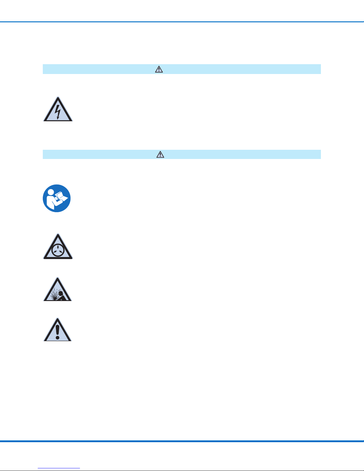
3. Use a pallet jack to lift a corner of the enclosure
and then use an adjustable open-end wrench to
install the feet. Repeat to install the remaining
feet.
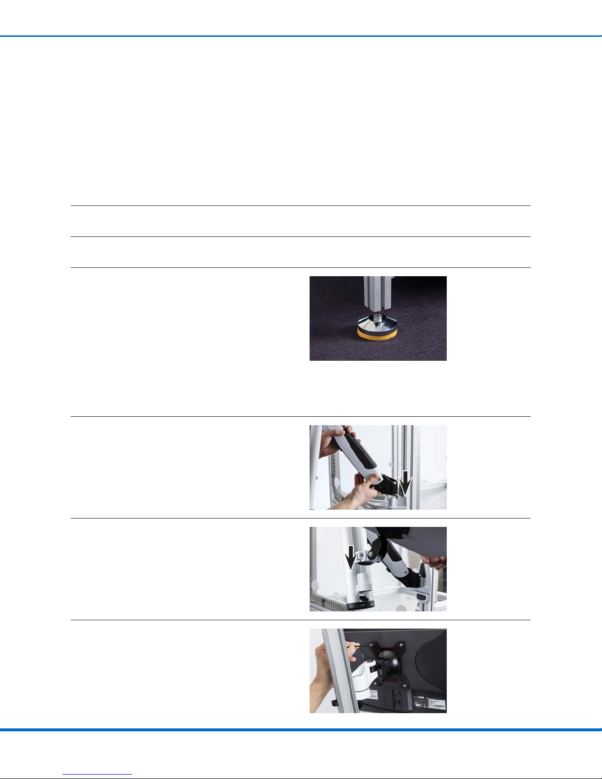
(Vision Systems Only) Install the Monitor and Keyboard
1. Install the articulating arm on the mounting base.
2. Install the keyboard tray on the articulating arm.
3. Use four (4) M4 x 12 screws (customer-supplied)
to secure the monitor to the monitor mounting
plate.
Safety Enclosure for Automated Dispensing Systems
12 www.nordsonefd.com [email protected] 800-556-3484 Sales and service of Nordson EFD dispensing systems are available worldwide.
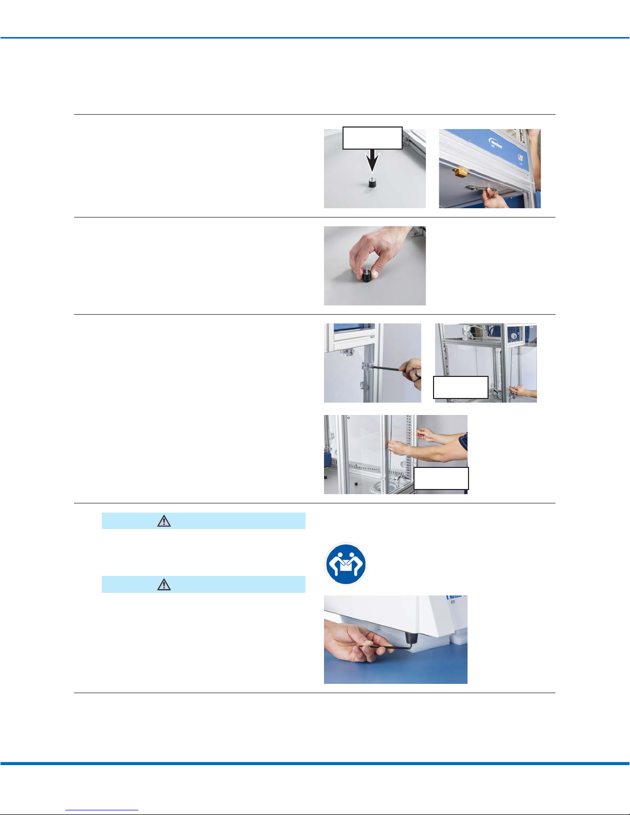
Install the Robot in the Enclosure
1. Open the enclosure doors and use an open-end
wrench to remove the M5 hex nuts that secure
the vibration isolators.
NOTE: The vibration isolators are secured to the
enclosure by a locking nut that is accessible only
by opening the enclosure doors.
Vibration isolator
(top view)
2. Remove the four (4) vibration isolators from the
enclosure.
3. a. Use a 5 mm hex key to remove the right-side
clear panel (9 screws) and the two back clear
panels (6 screws each).
b. Set the panels and screws aside in a safe
location. Right-side
panel removal
Back panel
removal
4.
Moving the robot requires a minimum of two
people. Do not attempt to lift the robot without
assistance.
WARNING
Avoid tilting the robot, and never lay the robot on
its side. Doing so can damage the circuitry.
CAUTION
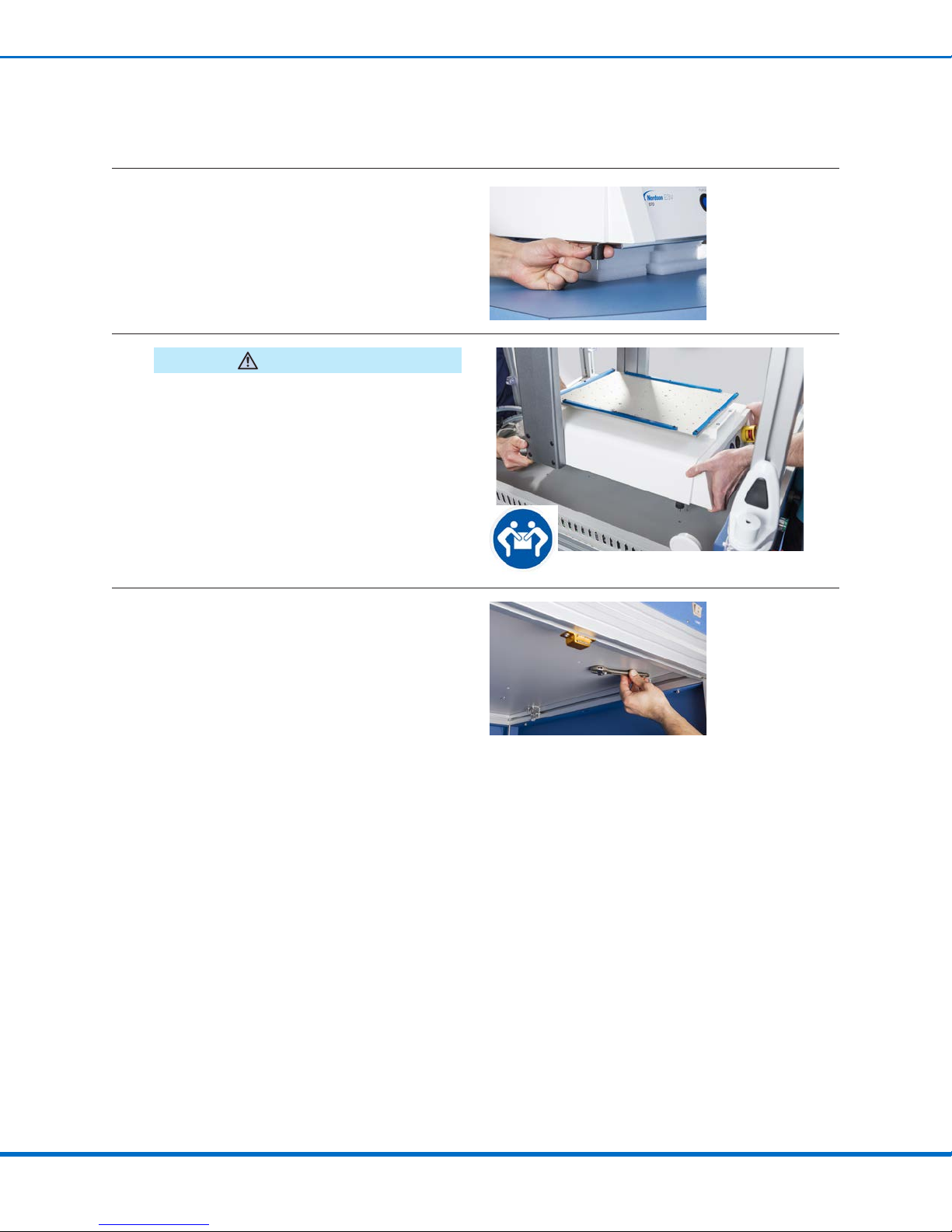
a. Use foam (or a similar methodology) to
carefully and safely elevate the robot such
that you can access the robot feet.
b. Use a 4 mm hex key to remove the four (4)
existing feet from the robot.
Continued on next page
Installation (continued)
13www.nordsonefd.com [email protected] 800-556-3484 Sales and service of Nordson EFD dispensing systems are available worldwide.
Safety Enclosure for Automated Dispensing Systems
5. By hand, install the vibration isolators (that were
removed from the safety enclosure) on the robot
where the robot feet were previously installed.
Hand tighten.
6.
Moving the robot requires a minimum of two
people. Do not attempt to lift the robot without
assistance.
WARNING
Position the robot inside the safety enclosure,
aligning the feet to the correct holes for your
robot model.
NOTE: The safety enclosure bottom provides
holes for the multiple robot sizes.
7. Open the enclosure doors and use an open-
end wrench to install the M5 nuts removed
previously, thus securing the robot to the
enclosure.
Installation (continued)
Install the Robot in the Enclosure (continued)
Safety Enclosure for Automated Dispensing Systems
14 www.nordsonefd.com [email protected] 800-556-3484 Sales and service of Nordson EFD dispensing systems are available worldwide.
Installation (continued)
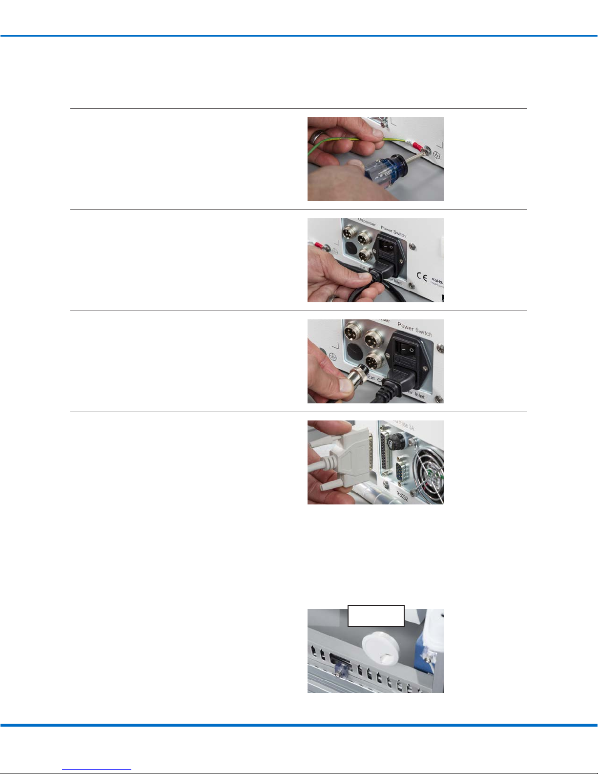
Connect Cables
1. Use a Phillips-head screwdriver to connect the
ground wire to the ground connection on the
back of the robot.
2. Connect the power cable to the Power Inlet.
3. Connect the input / output safety plug cable to
the Ext. Control port.
4. Connect the input / output (I/O) cable to the IO
Port.
5. (Vision systems only)
• Connect the monitor power and DispenseMotion™controller cables to the robot.
(Teach Pendant systems only)
• Connect the Teach Pendant to the Teach Pendant port on the front of the robot.
NOTES:
- Cables can be routed through the grommet
holes provided on all sides of the safety
enclosure.
- Refer to the Quick Start Guide for the
correct cable connections for your system.
Grommet for
cable routing
15www.nordsonefd.com [email protected] 800-556-3484 Sales and service of Nordson EFD dispensing systems are available worldwide.
Safety Enclosure for Automated Dispensing Systems
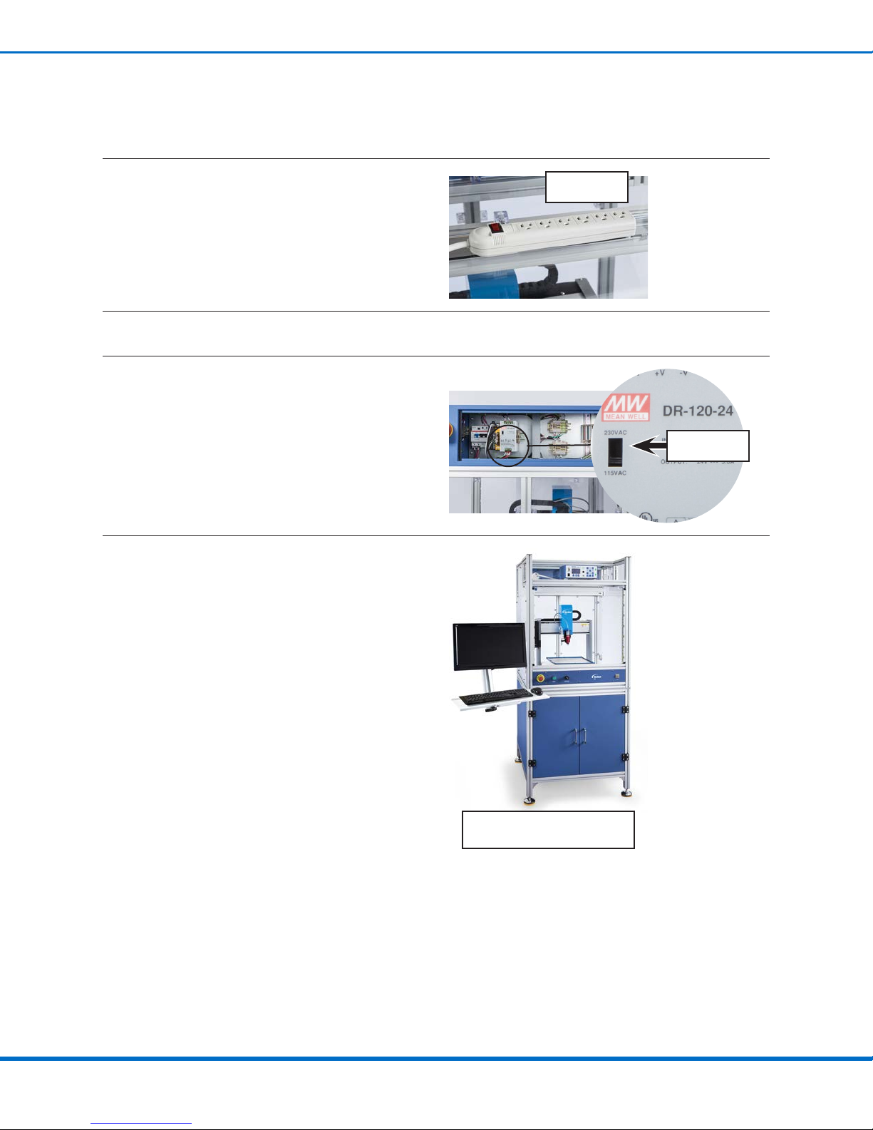
Install the Dispensing System and Reinstall the Panels
1. Install the dispensing system. Refer to the
dispensing component manuals for complete
installation instructions.
NOTE: A power strip is provided on the front
top of the enclosure. This location is ideal for a
dispense valve controller.
Power strip on
top of enclosure
2. Reinstall the back clear panels and the right-side clear panel using the screws removed previously.
3. a. Open the electrical box on the back of the
safety enclosure.
b. Set the 24V voltage supply switch to the
correct setting for your installation.
AC supply
voltage switch
The automated dispensing system is now fully
installed in the safety enclosure.
Continue to the next procedures to connect
inputs / outputs and to power on the complete
system for the rst time.
Example of a fully installed system
(EV Series system shown)
Installation (continued)
Safety Enclosure for Automated Dispensing Systems
16 www.nordsonefd.com [email protected] 800-556-3484 Sales and service of Nordson EFD dispensing systems are available worldwide.
Safety Enclosure I/O Terminal Block Pin Assignments
Block Number* Assignment Block Number* Assignment
Block 1 Input 1 Block 9 Output 1
Block 2 Input 2 Block 10 Output 2
Block 3 Input 3 Block 11 Output 3
Block 4 Input 4 Block 12 Output 4
Block 5 Input 5 Block 13 Output 5
Block 6 Input 6 Block 14 Output 6
Block 7 Input 7 Block 15 Output 7
Block 8 Input 8 Block 16 Output 8
Block 17 GND
Block 18 GND
*Each terminal block has a dedicated +24V terminal and ground rails for connecting external equipment.
The safety enclosure terminal block pin assignments extend to the 25-position I/O Port connector on the back of the
robot. Refer to the table below for robot I/O Port pin assignments.
Robot I/O Port Pin Assignments
Pin Assignment Pin Assignment
Pin 1 Input 1 Pin 14 Output 1
Pin 2 Input 2 Pin 15 Output 2
Pin 3 Input 3 Pin 16 Output 3
Pin 4 Input 4 Pin 17 Output 4
Pin 5 Input 5 Pin 18 Output 5
Pin 6 Input 6 Pin 19 Output 6
Pin 7 Input 7 Pin 20 Output 7
Pin 8 Input 8 Pin 21 Output 8
Pin 9 N/C* Pin 22 N/C*
Pin 10 N/C* Pin 23 N/C*
Pin 11 Ground* Pin 24 +24 VDC*
Pin 12 Ground Pin 25 +24 VDC*
Pin 13 Ground
*These signals are not connected to the safety enclosure I/O terminal block.
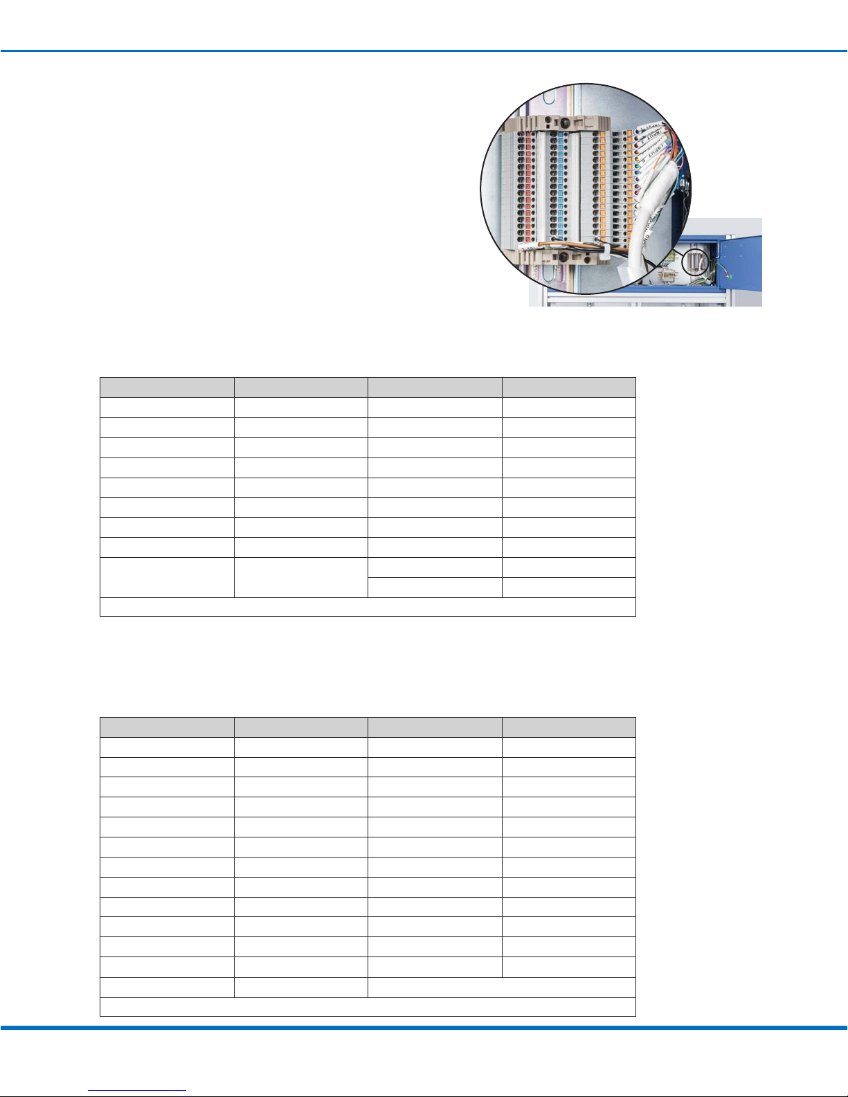
Installation (continued)
Location of the I/O terminal block inside the
electrical box
Connect Inputs / Outputs (Optional)
The electrical box on the back of the safety enclosure includes
an I/O terminal block. The terminal wires are labeled, and each
terminal provides a signal, power, and ground connection. This
terminal block mimics the functionality of the IO Port on the back
of the robot.
Make the I/O connections as needed for your operation.
NOTES:
• Outputs from the robot I/O Port are rated at 125 mA.
• Courtesy +24VDC output is rated at 5.0 Amp.
17www.nordsonefd.com [email protected] 800-556-3484 Sales and service of Nordson EFD dispensing systems are available worldwide.
Safety Enclosure for Automated Dispensing Systems
Initial Startup
NOTE: This startup procedure applies only to the rst power-on of the enclosure after installation. For routine
operation, refer to “Operation” on page 19.
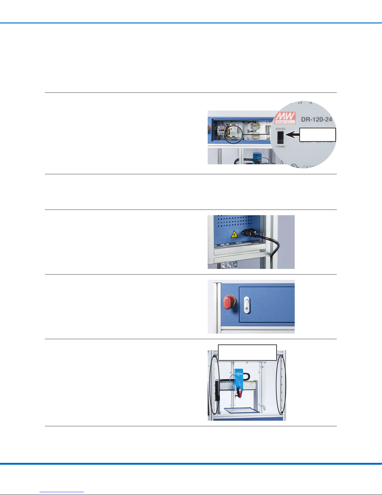
1. Verify that the 24V voltage supply switch inside the
electrical box is set to the correct voltage.
AC supply
voltage switch
2. Ensure that:
• All system cables are properly connected as applicable for your installation.
• The dispensing system installation is complete.
3. Connect the 5 m safety enclosure power cable to the
power inlet on the right side of the enclosure and to
the power source.
4. Turn the main disconnect switch located on the back
of the safety enclosure to the ON position.
When the system is powered on, the light curtain and
all I/O connections are automatically active.
If the light curtain is interrupted by any passing object
(such as a hand reaching into the enclosure), the
system enters an emergency stop condition.
Location of the light curtain
beams and sensors
Continued on next page
Installation (continued)

Safety Enclosure for Automated Dispensing Systems
18 www.nordsonefd.com [email protected] 800-556-3484 Sales and service of Nordson EFD dispensing systems are available worldwide.
Installation (continued)
Initial Startup (continued)
5. Open the DispenseMotion software and set “Out 8” to “Running.” Refer to the “I/O Pin Function Setup”
appendix in the robot operating manual for instructions.
NOTE: The system includes a relay switching pin that is connected to output 8 on the I/O terminal block.
When the output 8 signal exceeds 24V (goes “high”), the system breaks the circuit between EMG IN and
EMG OUT. When output 8 is high and the light curtain is broken, the Emergency Stop signal locks and
the robot enters a “hard lock” state. When Output 8 is low and the light curtain is broken, the Emergency
Stop signal is not triggered, meaning the robot is in a “soft lock” state. For the system to use this soft lock
feature correctly, output 8 (“Out 8”) in the DispenseMotion software must be set to Running.
DispenseMotion software screens used to set up Inputs / Outputs (refer to the robot operating manual for the complete
procedure)
19www.nordsonefd.com [email protected] 800-556-3484 Sales and service of Nordson EFD dispensing systems are available worldwide.
Safety Enclosure for Automated Dispensing Systems
Operation
Once the robot is properly installed in the enclosure, follow these procedures for
routine operation to ensure personnel safety.
Starting the System
1. Turn the main disconnect switch located on the back of the safety enclosure
to the ON position.
2. Refer to the robot operating manual for additional robot-specic power-on
steps (such as switching on the DispenseMotion controller).
NOTE: When the system is powered on, the light curtain and all I/O
connections are automatically active. If the light curtain is interrupted by
any passing object (such as a hand reaching into the enclosure), the system
enters an emergency stop condition. An emergency stop may also be
triggered by a customer-specic I/O connection.
3. Press the EMERGENCY STOP button to test it. If an emergency shutdown
occurs, the system is operating properly.
4. Verify that the light curtain is functioning properly by moving a
test object into the light curtain eld. If an emergency shutdown
occurs, the system is operating properly.
NOTE: Nordson EFD strongly recommends performing the
following additional checks of the light curtain operation:
• Ensure that the safety enclosure is in a location that is free of
light interference, such as from uorescent lamps.
• Check the sheaths of the wiring connected to the light curtain
controller (inside the electrical box) for damage and replace
any damaged wiring. Refer to “Service” on page 21 for the
location of the light curtain controller.
About the RUN/TEACH Switch
The safety enclosure provides a RUN/TEACH switch that affects
system operation. The default position of the RUN/TEACH switch is
the RUN position, which allows normal operation. Placing the switch
in the TEACH position deactivates the light curtain, allowing the
operator to run the robot at a reduced speed (without dispensing) or
to service the robot. When the RUN/TEACH switch is in the TEACH
position, the system will not run a dispense cycle.
When the RUN/TEACH switch is in the RUN position:
• The light curtain is active — any object that passes the light curtain causes an
emergency shutdown condition.
• Pressing the green START button starts a dispense cycle.
When the RUN/TEACH switch is in the TEACH position:
• The light curtain is deactivated, allowing the operator to reach inside the
enclosure without triggering an emergency shutdown.
• The robot cannot execute a dispense program.
Main disconnect switch
Controls on the front of the
safety enclosure (standard
enclosure shown)

Safety Enclosure for Automated Dispensing Systems
20 www.nordsonefd.com [email protected] 800-556-3484 Sales and service of Nordson EFD dispensing systems are available worldwide.
Operation (continued)
Controls on the front of a
standard safety enclosure
Controls on the front of an
EU safety enclosure
Running a Program
NOTE: These steps are for a typical operation and may vary depending on the
application.
1. Open the program to be run. Refer to the robot manual as
needed for instructions on opening a program.
2. Turn the RUN/TEACH switch to the TEACH position.
3. Place a workpiece on the robot work surface.
4. Turn the RUN/TEACH switch to the RUN position.
5. Use the green START button on the front of the safety enclosure
to run programs as follows:
• Press the START button to start a dispense cycle.
• While a dispense program is running, press the START button
a second time to pause the dispense cycle.
• Press a the START button a third time to resume a paused
dispense cycle.
Stopping the System (Emergency Stop)
An emergency stop condition occurs when the user presses the
EMERGENCY STOP button on the front of the safety enclosure or
when the light curtain eld is broken.
When an emergency condition occurs:
• The dispense cycle stops and cannot be restarted from the
stopped location
• The system requires a reset. Refer to “Resetting the System”
below.
Resetting the System
When an emergency stop condition occurs, follow these steps to
restart the system.
1. If applicable, correct the condition that caused the emergency
stop.
2. If the EMERGENCY STOP button is pressed in, turn it
clockwise to reset it.
3. (EU safety enclosures only) Press the blue RESET button to
re-enable power to the robot motors.
4. Press the START button to reset the position of the robot.
5. Resume normal operation.
This manual suits for next models
3
Table of contents


