Enginuity OnSite WR-10U23 User manual

WR-10U23 Sep2017
001-01-000092 Rev.000
OnSite™is a trademark ofEnginuityCommunications Corp. ©2017 EnginuityCommunications Corp. Page1 of5
OnSite™23”/10U Wall Rack
Model WR-10U23
1. OVERVIEW.................................................................1
2. APPLICATIONS......................................................... 1
3. DESCRIPTION........................................................... 2
4. INSTALLATION.......................................................... 2
5. TESTING AND TROUBLESHOOTING ................... 4
6. CUSTOMER SERVICE............................................. 4
7. WARRANTY & REPAIRS.......................................... 5
8. SPECIFICATIONS..................................................... 5
1. OVERVIEW
Enginuity’s OnSite™ ModelWR-10U23 (Figures1 and 2)
is a wall-mountedequipment rack that supports up toten
23-inch rack units (10U) in a compact footprint. Cable
management options include side-mounted guides for
cable grooming and take-up reelsfor cable slack. The
carrier-class assembly is an ideal fit for equipment rooms,
cabinets, or customer premises locations.
Document Status
This is a draft release of this technical publication.
Product Features
•10U height for 23-inch rack-mounted equipment
•Easily installed on a wall or backboard
•Welded, carrier-class design
•Optional side-mounted cable guides and take-up reels
•Reduces wall space requirements for multi-chassis
applications
2. APPLICATIONS
For service delivery, the WR-10U23 allows carriers to
securely wall mount rack-based equipment in equipment
rooms, cabinets, or on customer premises. The WR-
10U23 offers the following technician-friendly solutions:
Rack-Mount Compatibility
The WR-10U23 supports any combination of standard
23-inchrack-based equipment, up to a total of ten rack
units high. The mounting arrangement providesthe
densitybenefitsof a floor rack, but in a compact wall-
mounted footprint that requires only a single technician to
install.
Cable Management
Cable guides can be installed on either side of the WR-
10U23 to groom cablesfrom the front of each equipment
chassis back to the wall. A package of five cable guides is
available as Model CG-5.
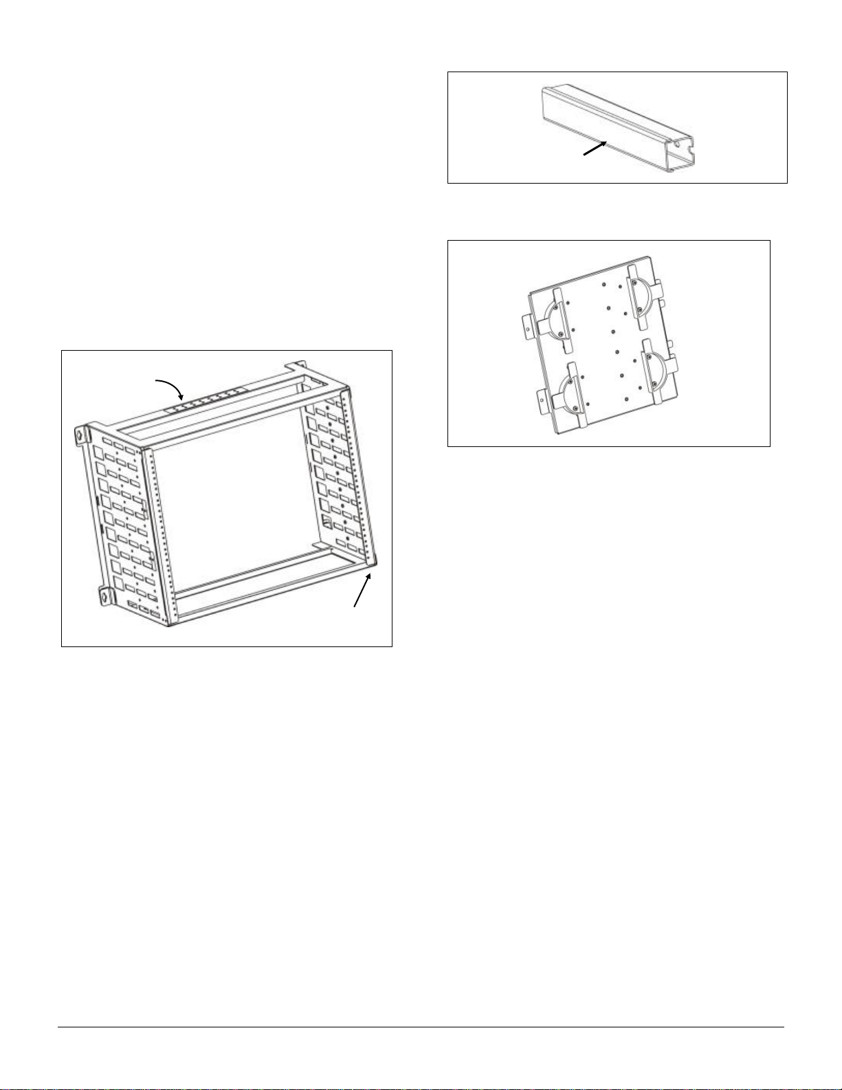
Figure 1. WR-10U23 Wall Rack
Figure 2. WR-10U23 w/ equipment installed (example)
001-01-000092 Rev. 000 Page2 of5
A side plate with cable take-up reels, Model SPL-4H, can
be added to store excess cable length being fed to
installed equipment. The SPL-4H mounts to either side of
the WR-10U23 and includes two adjustable, split reels.
3. DESCRIPTION
The WR-10U23 (Figure 3) features welded steel, carrier-
class construction. The front of the frame provides two
vertical railswith standard threaded hole spacing for up to
ten rack units. Eight pairs of threaded grounding holes
and pre-installed screws are provided on the rear
crossbar for attachment of ground lugs. One pair of holes
supports grounding of the WR-10U23 itself and the other
seven pairs of holes support ground connections from
installed equipment. The unpainted grounding area
provides metal-to-metal contact with ground lug surfaces.
Cable Guides
Optional cable guides with removable covers (Figure 4)
can be attached to either side of the WR-10U23 frame.
Upto ten cable guides can be installed per side.
Side Plate with Take-up Reels
Anoptional side plate, Model SPL-4H (Figure 5), provides
two adjustablecable take-up reels. The reels are sized to
maintain proper bend radius infiber applications. The
metal platecan be attached to either side of the WR-
10U23 frame using the included hardware.
4. INSTALLATION
The WR-10U23 shipping cartoncontainsthe following:
•Pre-assembled mounting frame
•Six (6) #12 x 1” slotted hex screws, self-tapping
•Product documentation
Installation stepsare described indetailbelow.
A. Mounting frame
Selectan appropriate location on awall or backboard
to installthe mounting frame. Choose amounting
surface and hardware that can support the combined
weight of the mounting assembly and equipment that
isto be installed. Mounting to a 3/4” thick backboard
with #12 x 1” screws isrecommended. Maximum
weight holding capacity of the WR-10U23 is 200 lbs.
Determine the desired orientation of the ground lugs.
The symmetrical design of the WR-10U23 frame
allows it to be installed with the grounding holesfacing
upward or downward.
Hold the emptymounting framefirmlyagainst the wall
or backboard in a level position and mark screw
locations for each of the four mounting brackets
located at the rear corners of the frame. The frame will
be fastened with two screws in each of the upper
brackets and one screw in each of the lower brackets,
as shown in Figure 6.
Figure 3. WR-10U23 Features
Figure 4. Cable guide
Figure 5. Model SPL-4H Side Plate
Slide on/off cover
Threaded
grounding holes
Standard threaded hole
spacingfor up to10 rack units
001-01-000092 Rev. 000 Page3 of5
Remove the mounting frame from the wall and drill
pilot holes for each of the marked screw locations.
Before attempting to fasten the mounting frame to the
wall, insert a screw into the toppilot hole oneither the
left or right side. Partially thread the screw into the
hole, leaving the screw head approximately 1/4” from
the surface.
Hold themounting frame against the wall while resting
the cutout of the bracket on the installed screw.Align
the other five mounting holes and install a screw in
each hole. Tighten all six (6) screws securely.
B. Frame grounding
Locate the eight (8) pairs of pre-installed grounding
screws with lock washers on the crossbar of the
frame. The grounding screws are 10-32 x 3/8” on 5/8”
centers.
Install a dualground lug (customer provided) with
holes on 5/8” centers beneath the included screws
and washers onone pair of grounding holes. Tighten
the screws to fasten the lug to the mounting frame.
The example in Figure 7 illustrates the frame
positioned with grounding screws facing downward.
Connect a ground wire of appropriate gauge tothe
ground lug, and attachthe other end of thewire to a
bonded ground point, per local proceduresfor network
equipment.
C. Equipment Installation
Install rack equipment with 23” hole spacing by
carefully sliding the chassis through the front of the
WR-10U23 and aligning chassis mounting ears with
the threaded holes in the rails of the WR-10U23
frame. Insert and tighten #12-24 machine screws
(customer provided) oneach side of thechassis. An
example of a fully populated wall rack is shown in
Figure 2.
Attach ground lugs associatedwitheach equipment
chassis to the threaded ground holes onthe WR-
10U23 crossbar as needed.
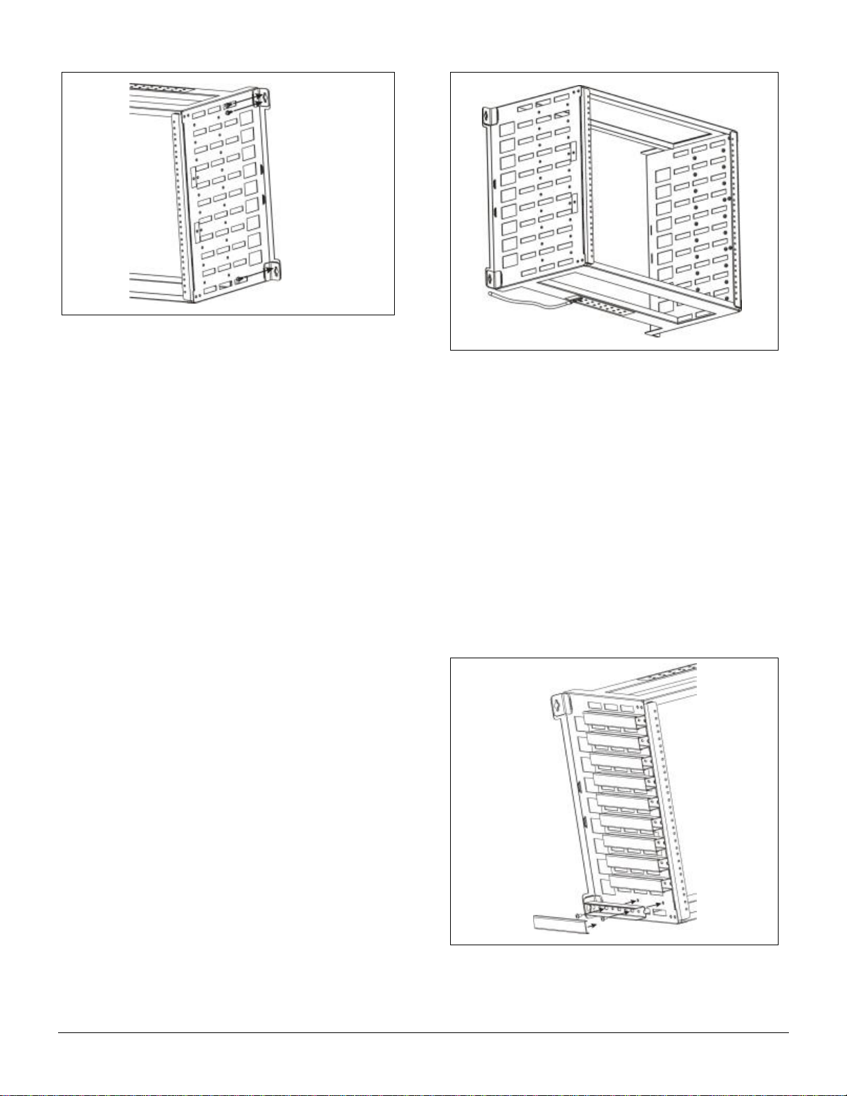
D. Optional Cable Guide Installation
To install a cable guide to the side of the mounting,
first remove the sliding cover from the cable guide.
Insert two of the #10-32 x 3/8” screws (included in
CG-5 package)through the cableguide and into the
threaded holes onthe side of the WR-10U23 frame
(Figure 8).
Groom cabling from the front of the chassis to the wall
through the cable guide on the side of the WR-10U23,
as shown inFigure 9, and replace the sliding cover.
Figure 6. Mounting screw locations
Figure 7. Frame grounding example
Figure 8. Cable guide installation
001-01-000092 Rev. 000 Page4 of5
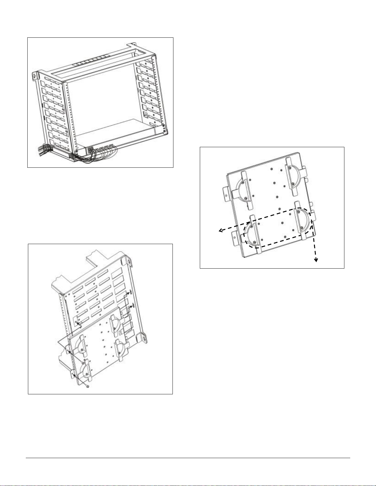
E. Optional Side Plate Installation
Threaded holes on both sides of the WR-10U23 frame
allow anoptional side plate (Model SPL-4H) or additional
cableguides to be installed to expand cable
management. The SPL-4H provides two split and
adjustable take-up reels, as illustrated inFigure 5.
To install and use the SPL-4H side plate, refer to Figure
10 andthe steps below.
Slide the two narrower tabs at the edge of theSPL-4H
into the openings on the side of the WR-10U23,
toward the rear of themounting.
Align the wide tabs at the front edge of the SPL-4H
with the threaded holes on the side of the WR-10U23
frame. Use the two (2) included #10-32 x3/8” screws
to securely fasten the side plate to the frame.
Carefullywrap cables around the take-up reels to
reduce slack as needed. Example routing is shown in
Figure 11. Alternate mounting holesare included on
the side plate for repositioning the half-reels, if desired.
5. TESTING AND TROUBLESHOOTING
Equipment installed in the WR-10U23 should betested
according the manufacturer’s instructions.
6. CUSTOMER SERVICE
Customer Sales and General Support
Monday through Friday, 8:00 a.m.–5:00 p.m. CST
Toll Free: 800-980-ECOM (3266), Local: 630-444-0778
24/7 SalesSupport: sales@enginuitycom.com
24/7 Technical Support:
Toll Free: 800-841-1005
E-mail: support@enginuitycom.com
Enginuity Communications
3545 Stern Avenue
St. Charles, IL 60174
Figure 9. Cable guide application
Figure 10. SPL-4H installation
Figure 11. Cable take-up reel routing

001-01-000092 Rev. 000 Page5 of5
7. WARRANTY & REPAIRS
Warranty
Enginuity warrants this product for one (1) year from date
of purchase. Any attempt to repair or modify the
equipment by anyone other than an authorized Enginuity
representative will void thewarranty.
This limited warranty does not cover any losses or
damages resulting from shipment to or from the
customer, or from improper installation, abuse,
modifications, or unauthorized repair by other than
Enginuity personnel.
Repair and Return
Enginuityequipment will be repaired or replaced without
cost during the warranty period if the product is defective
for any reasonother than abuse, improper use, or
improper installation. Before returning defective
equipment, first request a Return Material Authorization
(RMA) numberfrom Enginuity. Once anRMA number is
obtained, return the unit, freight prepaid, along with a brief
description of the problem, to:
Enginuity Communications
3545 Stern Avenue
St. Charles, Illinois 60174
ATTN: Repair & ReturnDept.
Replacements will be shipped in the fastest manner
consistent with the urgency of the situation. Repair or
replacement of faulty equipment beyond thewarranty
period is availablefor a nominal charge.
8. SPECIFICATIONS
Mounting Frame
Part Number
WR-10U23
Description
OnSite™ 23”/10U wall rack
Height
19.25 inches
Width
26.7 inches
Depth
12.6 inches
Weight
14.8 pounds
Capacity
10 rack units, total installed equipment weight not to exceed 200 lbs.
Operating Temperature
0 to 50C
Standards Compliance
Meets applicable Telcordia NEBS requirements, including Zone 4 seismic.
Optional Side Plate
Part Number
SPL-4H
Description
Side plate for wall rack with (2) adjustable take-up reels
Height
10.5 inches
Width
11.3 inches
Depth
1.3 inches
Weight
2.5 pounds
Additional Cable Guides
Part Number
CG-5
Description
Pack of (5) cable guides for wall rack
Height
1.0 inches (each)
Width
1.3 inches (each)
Depth
7.8 inches (each)
Weight
2.0 ounces (each)
Table of contents
Other Enginuity Enclosure manuals

Popular Enclosure manuals by other brands


SPACE AGE ELECTRONICS
SPACE AGE ELECTRONICS SSU-WP-2000 manual

TOOQ
TOOQ TQE-2510B user manual

HGST
HGST Ultrastar Serv60+8 installation guide

DeLOCK
DeLOCK 42633 user manual

Dormakaba
Dormakaba Crane 4000LE Installation, Setup and Troubleshooting Manual

Extron electronics
Extron electronics PowerCage 1600 user guide

StorageWorks
StorageWorks EK-SMRAB-IG installation guide

Compaq
Compaq 4354R - StorageWorks Enclosure Storage Addendum

Icy Box
Icy Box IB-WF200HD manual

Akitio
Akitio Taurus Mini Super-S3 LCM Setup guide

Cooler Master
Cooler Master ATCS 840 installation guide

Kinedo
Kinedo Kinespace 2P installation instructions