NORIS VD61 User manual

Instruction Manual
VD61
NAN-KD-0031-EN_V01.01 | 05/05/2021

| Issue NORIS Automation GmbH
2/ 23 Instruction Manual VD61
Issue
Information on issue
Document ID NAN-KD-0031-EN
Issue V01.01
Date April 2021

NORIS Automation GmbH Table of contents
Instruction Manual VD61 iii
Table of contents
1General information 4
2General information on this instruction manual 6
2.1 Scope of validity 6
2.2 Subject of the instruction manual 6
2.3 Use of safety and warning notes 6
2.4 Scope of delivery 7
2.5 Accessories and spare parts 7
3Product description 8
3.1 Safety notes 8
3.2 Scope of application 9
3.3 Measuring principle 9
3.4 Type code 9
4Technical data 10
5Installation and commissioning 13
5.1 Tools and equipment 13
5.2 Dimensions 14
5.3 Installation 16
5.4 Electrical connection 18
6Maintenance 20
7De-installation and disposal 21
8Troubleshooting 22
9Service 23

1| General information NORIS Automation GmbH
4/ 23 Instruction Manual VD61
General information
Use for intended purpose
▪ Theproductmayonlybeusedfortheapplicationsspecifiedinthis
document and in the technical documentation. Transportation with due
care and attention, correct storage and installation as well as careful
use and maintenance during operation of the product must be ensured
to guarantee trouble-free and safe operation.
▪ Theproductmustbeusedatalltimesinagreementwiththetechnical
specifications. In particular, compliance with the ambient conditions
recommended in the technical documentation must be ensured.
Installation, assembly, repair and maintenance work
▪ Observetherelevantnationalregulationsandobservetheapplicable
standards and directives for special applications.
▪ Installation,assembly,repairandmaintenanceworkmustbecarried
out exactly according to the installation and maintenance instructions
applicable to the individual products in order to guarantee their func-
tional reliability and avoid installation errors and damage.
▪ Installation,assembly,repairandmaintenanceworkmustonlybeper-
formed by qualified and authorised technical personnel in accordance
with the relevant documentation, especially the safety and warning in-
formation contained therein.
▪ Makesurethatnoexcessparts(screws,tools,etc)areleftbehindin
or on products after performing installation, assembly, repair or main-
tenance work. Non-compliance with this requirement may cause mal-
functions and/or damage to the products or the system.
▪ Makesureafunctiontestiscarriedoutoncompletionofinstallation,
assembly, repair and maintenance work to ensure trouble-free opera-
tion of the products.
Suitable tools and equipment
Onlysuitabletoolsandequipment,especiallymaterialsprovidedbyNO-
RIS, are to be used for installation, assembly, repair and maintenance
work. Damaged products or components are to be replaced only by genu-
ineNORIScomponentsorparts.NORISshallacceptnoliabilitywhatsoev-
er for any damage incurred as the result of using unauthorised spare parts.
This will invalidate the warranty. Keep the operating instructions in a place
that is accessible to all users at any time.
Modification of products
NORISshallacceptnoliabilitywhatsoeverifunauthorisedmodifications
have been made to the products. This will also invalidate the warranty.
Therefore, consult our technical staff before undertaking any modifications.
1

NORIS Automation GmbH General information | 1
Instruction Manual VD61 5/ 23
Shipping, appropriate storage and packaging
Products that are sent in for repair must be appropriately packaged to pre-
ventdamage(fromimpacts,moisture,staticcharge,etc).Makesurethat
products and all spare parts are stored correctly. Refer to the correspond-
ing technical information for further information.
Disclaimer
We review the contents of our technical documentation at regular intervals
to ensure it agrees with our products. Nevertheless, variations cannot be
completelyruledout.NORISthereforecannotguaranteecompleteagree-
ment of the documentation contents with the hardware and software.
Changes and corrections will be included in subsequent issues of the tech-
nical documentation.

2| General information on this instruction manual NORIS Automation GmbH
6/ 23 Instruction Manual VD61
General information on this instruction
manual
Scope of validity
This instruction manual applies to the sensors listed below:
Sensor type Product revision
VD61 A
Important information on the use of this instruction manual
and supplementary information
In addition to the information in this instruction manual, refer also to the in-
formation in the customer drawing for installation, commissioning and oper-
ation.
Subject of the instruction manual
The subject of this instruction manual is the installation, commissioning,
operation and maintenance of pressure transmitter series VD61. Further-
more, this instruction manual also contains important troubleshooting infor-
mation.
Use of safety and warning notes
Warning about the type and source of immediate danger that
leads to death or serious injuries when disregarding the given
precautions.
Warning about the type and source of danger that may possibly
lead to death or serious injuries when disregarding the given
precautions.
Warning about the type and source of danger that may lead to
minor injuries when disregarding the given precautions.
Warning about the type and source of danger that may lead to
material damages when disregarding the given precautions.
2
2.1
2.2
2.3
DANGER
WARNING
CAUTION
NOTICE

NORIS Automation GmbH General information on this instruction manual | 2
Instruction Manual VD61 7/ 23
Scope of delivery
Pressure transmitters type series VD61 are delivered without accessories.
Accessories have to be ordered separately.
Accessories and spare parts
Available accessories
Adapter with G½ male
thread
Attenuator with G½ male thread
Pos. Description Drawing no. Order no.
01 Adapter with G½ male thread 59.201 522004
02 Attenuator K6 for heavy oil 59.201 522001
03 Attenuator K7 for light oil 59.201 522002
04 Attenuator K8 for air/water 59.201 522003
Available spare parts
There are no additional spare parts available for pressure transmitters type
series VD61.
2.4
2.5
3| Product description NORIS Automation GmbH
8/ 23 Instruction Manual VD61
Product description
Safety notes
Select the appropriate pressure transmitter with regard to scale
range, performance, medium-contacting parts and specific
measurement conditions prior to installing and starting the in-
strument
Otherwisethetransmittercandbedamaged.
Observe the relevant national regulations and observe the ap-
plicable standards and directives for special applications (e.g.
with dangerous media such as acetylene, flammable gases or
liquids and toxic gases or liquids and with refrigeration plants
or compressors).
If you do not observe the appropriate regulations, serious injuries
and/or damage can occur!
Open pressure connections only after the system is without
pressure!
Please make sure that the pressure transmitter is only used
within the overload threshold limit all the time!
Observe the ambient and working conditions outlined in „Tech-
nical data”.
Observe the technical data for the use of the pressure transmit-
ter in connection with aggressive / corrosive media and for the
avoidance of mechanical hazards. Open circuit before removing
connector / cover.
Ensure that the pressure transmitter is only operated in accord-
ance with the provisions i.e. as described in the following in-
structions.
Do not interfere with or change the pressure transmitter in any
other way than described in these operating instructions.
Remove the pressure transmitter from service and mark it to
prevent it from being used again accidentally, if it becomes
damaged or unsafe for operation.
Otherwiseseriousinjuriesmayoccurandthetransmittercanbe
damaged.
Take precautions with regard to remaining media in removed
pressure transmitter.
Remaining media in the pressure port may be hazardous or toxic!
3
3.1
NOTICE
CAUTION
CAUTION
CAUTION

NORIS Automation GmbH Product description | 3
Instruction Manual VD61 9/ 23
Scope of application
Series VD61 pressure transmitters are mainly used in: Shipbuilding indus-
try, transport technology, machinery and equipment. They measure the
pressure of liquid or gaseous media.
Caution: An unsuitable pressure medium can damage or even
destroy the pressure sensor!
Therefore, please check whether the pressure medium is suitable
for the medium-contacting parts of the pressure sensor before in-
stallation and use. For further information please read the technical
data.
Measuring principle
The pressure prevailing within the application is transformed into a stand-
ardised electrical signal through the deflection of the diaphragm, which
acts on the sensor element with the power supply fed to the transmitter.
This electric signal changes in proportion to the pressure and can be eval-
uated correspondingly.
Type code
Type code structure
VD 6 1 -15 Example: VD61-15
Construction type 6
Signal output
Measuring range
Type code VD61-…
Construction
type
6Construction type 6
Signal output 14 … 20 mA
Measuring
range
-_ _ _ See table "'Measuring range' [}11]"
VD 6 1 -300 Example: VD61-300
3.2
NOTICE
3.3
3.4

4| Technical data NORIS Automation GmbH
10 / 23 Instruction Manual VD61
Technical data
Electrical connection
Supply voltage 8 ... 30 VDC
Current limitation Power supply by energy-limited electrical circuit
in accordance with 9.3 of UL/EN/IEC 61010-1
or LPS in accordance with UL/EN/IEC 60950-1
or Class 2 in accordance with UL1310/UL1585
(NECorCEC)(thepowersupplymustalsobe
suitable for operation at an altitude above 2000
m,ifusedintheseheights)
Reverse voltage protec-
tion
X1+ against X1-
Electrical connection Connecting terminal for max. 1.5 mm²
Pressure connection G¼femalethread(adapterforG½malethread
available,seeaccessories)
Signal acquisition
Standard measuring
range
See measuring range table
Electrical output
Outputsignalandmaxi-
mum permissible load
4...20mA,2-wire,RA≤(UB-8V)/0.02A
Accuracy ≤±1%oftherange(includingnon-linearity,
hysteresis, zero point and final value deviation
(IEC6198-2))
Non-linearity ≤±0.5%ofrange
Non-repeatability ≤0.1%ofrange
Long-term drift ≤±0.1%ofrange(underreferenceconditions)
Transient response Transient recovery time < 4 ms;
turn on-time < 15 ms
Environmental influences
Operatingtemperature Permissible measured medium temperature:
-30 ... +100 °C
Permissible ambient temperature:
-30 ... +100 °C
Storage temperature -30 ... +100 °C
Vibration resistance IEC60068-2-6:10g(resonance)
Shock resistance IEC60068-2-27:500g(mechanical)
Protection class IP64 according to EN 60529
4

NORIS Automation GmbH Technical data | 4
Instruction Manual VD61 11 / 23
Mechanical properties
Material Parts in contact with measured medium: < 10
bar CrNi steel 303 and CrNi steel 316L; > 10
barCrNisteel316Land13-8PH(AISI),hous-
ing:Aluminium,powder-coated(checkthe
pressure medium for suitability for medi-
um-contactingparts)
Weight Approx. 560 g
Other
Approvals DNV
CE Conformity Pressure Equipment Directive 97/23/EC; EMC
Directive 2004/108/EC EN 61326 Emission
(Group1,ClassB)andinterferenceimmunity
(industrialenvironment)
Measuring range VD61
Code Measuring range Overload
1 0 ... 1 bar 2 bar
1,6 0 ... 1.6 bar 3.2 bar
2,5 0 ... 2.5 bar 5 bar
3 0 ... 3 bar 6 bar
4 0 ... 4 bar 8 bar
5 0 ... 5 bar 10 bar
6 0 ... 6 bar 12 bar
10 0 ... 10 bar 20 bar
15 0 ... 15 bar 30 bar
16 0 ... 16 bar 32 bar
20 0 ... 20 bar 40 bar
25 0 ... 25 bar 50 bar
30 0 ... 30 bar 60 bar
40 0 ... 40 bar 80 bar
50 0 ... 50 bar 100 bar
60 0 ... 60 bar 120 bar
100 0 ... 100 bar 200 bar
120 0 ... 120 bar 240 bar
150 0 ... 150 bar 300 bar
160 0 ... 160 bar 320 bar
180 0 ... 180 bar 360 bar
250 0 ... 250 bar 500 bar
300 0 ... 300 bar 600 bar
400 0 ... 400 bar 800 bar
600 0 ... 600 bar 1200 bar
150P 0 ... 150 psi 300 psi
1M1 -1 ... 1 bar 4 bar

4| Technical data NORIS Automation GmbH
12 / 23 Instruction Manual VD61
Measuring range VD61
1,6M1 -1 ... 1.6 bar 5.2 bar
2,5M1 -1 ... 2.5 bar 7 bar
3M1 -1 ... 3 bar 8 bar
4M1 -1 ... 4 bar 10 bar
Preferred types
Features marked with a symbol at the end of the line are preferred fea-
tures. If you select a preferred feature for each placeholder, the device is
specified as preferred type. Preferred types are available quickly from
stock.Othertypeswillbedeliveredaccordingtoscheduledappointments.

NORIS Automation GmbH Installation and commissioning | 5
Instruction Manual VD61 13 / 23
Installation and commissioning
Tools and equipment
Have the following tools and equipment ready for commissioning:
▪ Open-endedspanner(spannerwidth27)
▪ Screwdriver
Make sure that the tools and equipment are in perfect working
order.
Otherwisethepressuretransmittercanbedamaged.
5
5.1
NOTICE
5| Installation and commissioning NORIS Automation GmbH
14 / 23 Instruction Manual VD61
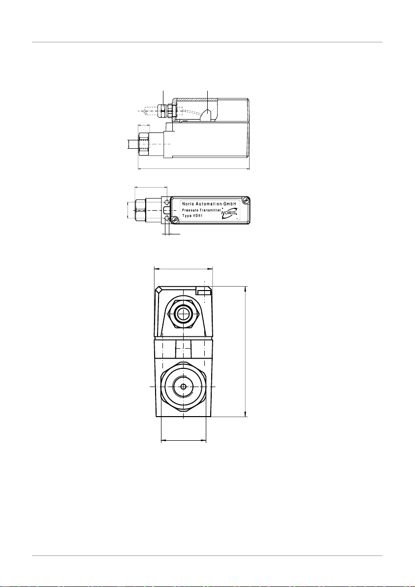
Dimensions
AB
C
D
E
Side view
A)CableglandM16(cableØ5…10
mm)
B)Terminalforcableupto1.5mm2
C)15mm
D)G1/4femalethread
E)146mm
B
A
C
Top view
A)40.5mm
B)20mm
C)Ø5.3mm
A
B
C
Front view
A)35mm
B)78mm
C)WAF27
5.2

NORIS Automation GmbH Installation and commissioning | 5
Instruction Manual VD61 15 / 23
E
A
B
C
D
F
E
A
B
C
D
F
Adapter with G½ male
thread
A)32mm
B)5mm
C)Ø6mm
D)G1/2
E)WAF22
F)Material1.4435
Attenuator with G½ male thread
A)32mm
B)5mm
C)Ø6mm
D)G1/2
E)WAF22
F)Material1.4435
5| Installation and commissioning NORIS Automation GmbH
16 / 23 Instruction Manual VD61
Installation
Install the transmitter in your application in compliance with the following
notes:
▪ Duringmounting,makesurethatthesealingandsealingfacesare
clean and undamaged.
▪ Whenscrewingin,donotcrossthethreads.Thismaydamagethe
transmitter.
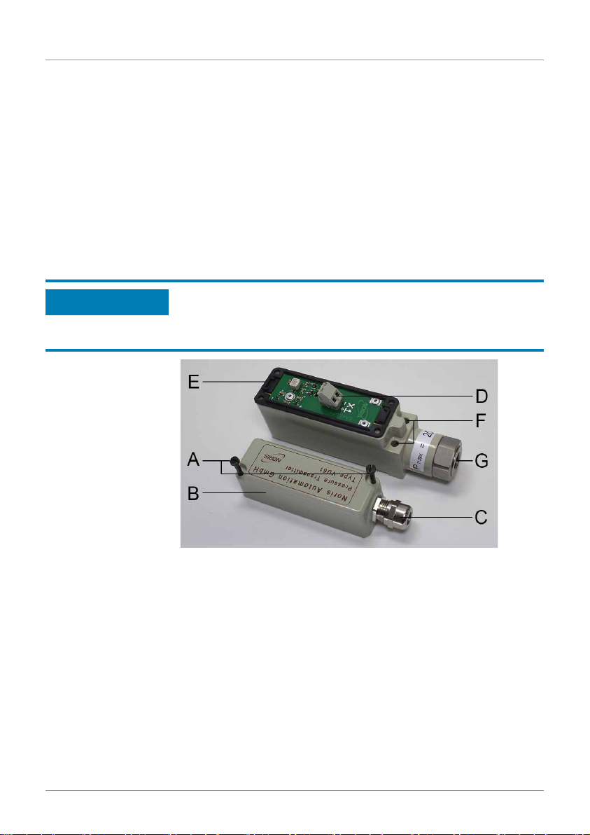
Follow the instructions to install the pressure transmitter
A. Screw the pressure transmitter on the mounting surface. Therefore,
twoboreholesarelocatedinthetransmitterhousing(seenextfig.,
Pos.F).Therefore,useappropriatescrews(typeM5,e.g.M5x45).
Type of screw and screw length depend on the mounting surface.
Ensure that the pressure transmitter is bolted down tightly on
the surface.
Otherwisethepressuretransmitterandthepipeconnectioncanbe
damaged.
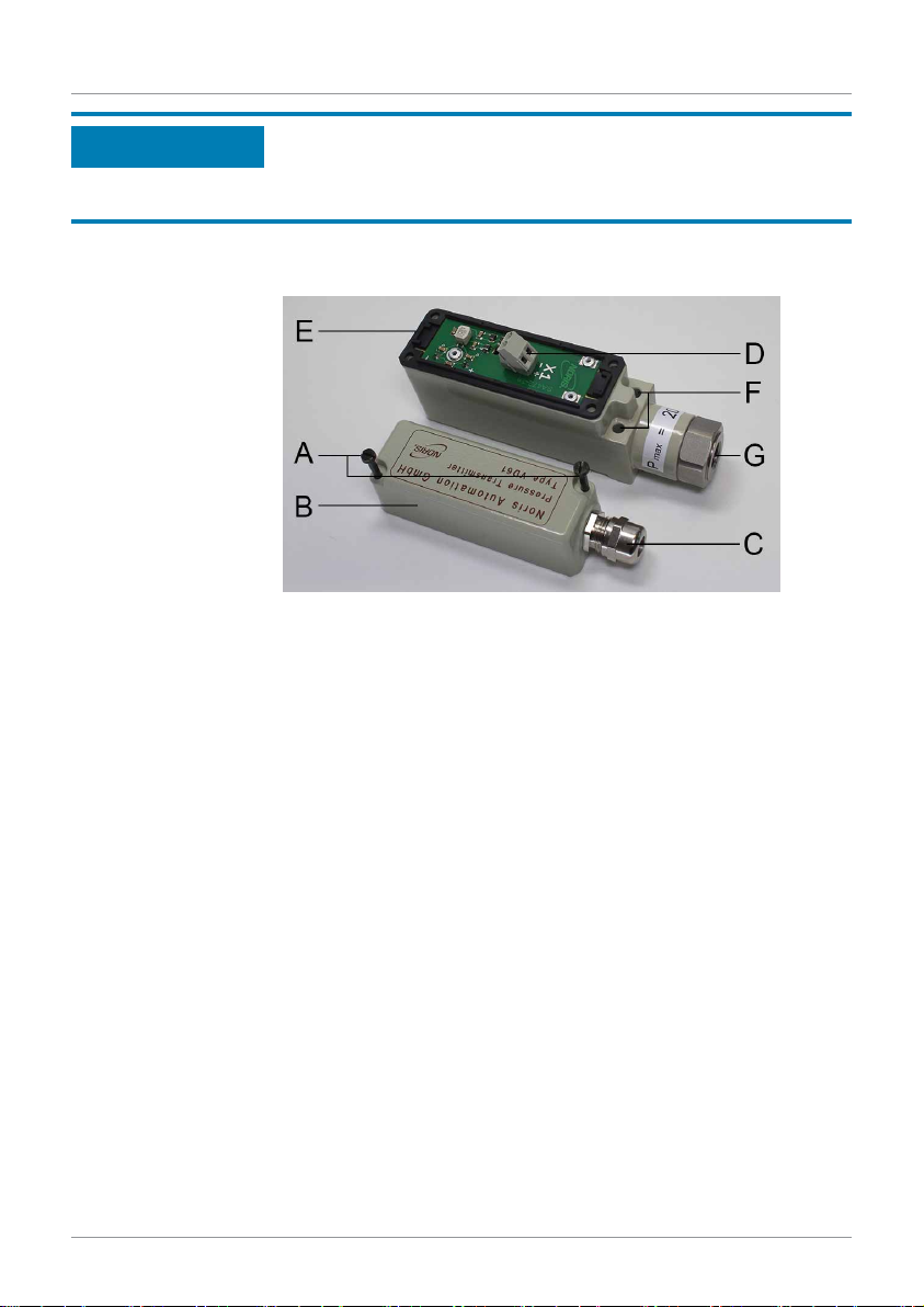
1: VD61 opened with markings
Follow the instructions to install the pressure connection
5.3
NOTICE
NORIS Automation GmbH Installation and commissioning | 5
Instruction Manual VD61 17 / 23
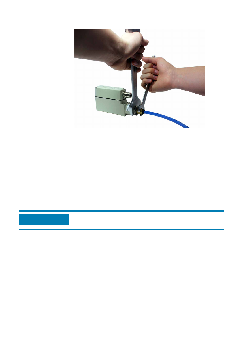
2: VD61-10 pressure connection
A. Connect the pressure connection appropriately to the pressure
transmitter.
➩Use an open-ended spanner to counter the screw connection.
Therefore,usethenutofthepressuretransmitter(seeprevi-
ousfig)andnotthetransmitterhousing.
➩When screwing, do not cross the threads.
➩If you use an attenuator or an adapter, screw it between the
pressure transmitter and the pressure connection. Pay atten-
tion that you also use the nut of the pressure transmitter for
countering. The screw connection must be seal and fixed
properly.
Avoid improper installation!
Otherwisethepressuretransmittercanbedamaged.
NOTICE

5| Installation and commissioning NORIS Automation GmbH
18 / 23 Instruction Manual VD61
Electrical connection
Note the following instructions for electrical transmitter connection:
▪ Thepressuretransmittermustbegroundedviatheprocessconnec-
tion.
▪ Thepowersupplyforthepressuretransmittermustbemadeviaan
energy-limited electrical circuit in accordance with section 9.3 of UL/
EN/IEC 61010-1, or an LPS per UL/EN/IEC 60950-1, or class 2 in ac-
cordancewithUL1310/UL1585(NECorCEC).Thevoltagesupply
must be suitable for operation above 2,000 m should the pressure
transmitter be used at this altitude.
▪ Makesurethatnomoistureentersthecableend.
X1+
X1-
VD61 Connection diagram
Follow the instructions to connect the cable to the pressure transmit-
ter
A. Loosenthetwoscrews(seenextfig.,Pos.A).
B. Opencarefullythecovering(seenextfig.,Pos.B)
C. Loosenthecablegland(seenextfig.,Pos.C)andinsertthecable
through the cable gland.
➩Therefore, use a cable with a diameter of 5 ... 10 mm and a cross
section of max. 1.5 mm2.
D. Connectthewiringaccordingtoconnectiondiagram(seeprevious
fig.)totheconnectionterminalofthepressuretransmitter.Notethe
terminal markings X1+ and X1- on the connection circuit board. The
use of wire end ferrules is recommended.
E. Close the covering.
➩Ensure the correct position of the sealing: The flat side must be
layedonthetransmitterhousing(seenextfig.,Pos.E).
5.4
NORIS Automation GmbH Installation and commissioning | 5
Instruction Manual VD61 19 / 23
If the sealing is not installed correctly, moisture can enter the
transmitter housing!
This may lead to incorrect measurement, signal loss or may even
damage the transmitter.
F. Screw the covering onto the housing by using both screws.
G. Fix the cable gland and check whether the cable is tightly fixed.
3: VD61 opened with markings
NOTICE

6| Maintenance NORIS Automation GmbH
20 / 23 Instruction Manual VD61
Maintenance
This transmiter is maintenance-free. Repairs must only be carried out by
the manufacturer. However, note the following instructions for cleaning, if
the transmitter is damaged and you have to remove it or before you send it
back to the manufacturer.
▪ Beforecleaning,correctlydisconnectthepressuretransmitterfromthe
supply voltage and the pressure supply.
▪ Cleantheinstrumentwithamoistcloth.CAUTION! Do not touch the
measuring material, if used with media that may harm people.
Otherwise serious injuries can be the result.
▪ Washorcleanthedismountedinstrumentbeforereturningit,inorder
to protect persons and the environment from exposure to residual me-
dia. CAUTION! Residual media in dismounted devices could harm
people and environment.
▪ Takesufficientprecautionarymeasures.
▪ NOTICE! Do not use any pointed or hard objects for cleaning, as
they may damage the diaphragm of the process connection.
6
Maintenance
Cleaning
Table of contents


