manuals.online logo
Brands
  1. Home
  2. •
  3. Brands
  4. •
  5. Endress+Hauser
  6. •
  7. Transmitter
  8. •
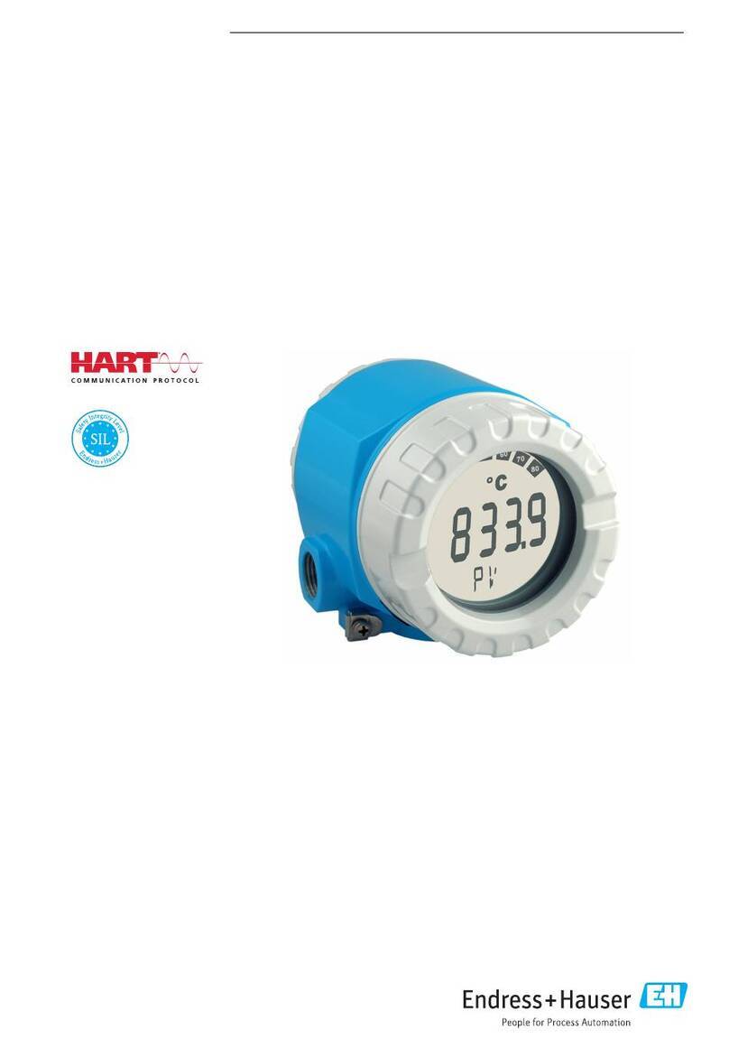
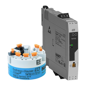
  9. Endress+Hauser HART iTEMP TMT182B User manual

Endress+Hauser HART iTEMP TMT182B User manual

Products Solutions Services
Operating Instructions
iTEMP TMT182B
Temperature transmitter
BA02260T/09/EN/01.22-00
71590122
2022-08-30
About this document iTEMP TMT182B
2 Endress+Hauser
1 About this document
1.1 Document function
These Operating Instructions contain all the information required in the various life cycle
phases of the device: from product identification, incoming acceptance and storage, to
installation, connection, operation and commissioning, through to troubleshooting,
maintenance and disposal.
1.2 Safety instructions (XA)
When using in hazardous areas, compliance with national regulations is mandatory.
Separate Ex-specific documentation is provided for measuring systems that are used in
hazardous areas. This documentation is an integral part of these Operating Instructions.
The installation specifications, connection data and safety instructions it contains must be
strictly observed! Make sure that you use the right Ex-specific documentation for the right
device with approval for use in hazardous areas! The number of the specific Ex
documentation (XA...) is provided on the nameplate. If the two numbers (on the Ex
documentation and the nameplate) are identical, then you may use this Ex-specific
documentation.
1.3 Symbols used
1.3.1 Safety symbols
DANGER
This symbol alerts you to a dangerous situation. Failure to avoid this situation will result in
serious or fatal injury.
WARNING
This symbol alerts you to a dangerous situation. Failure to avoid this situation can result in
serious or fatal injury.
CAUTION
This symbol alerts you to a dangerous situation. Failure to avoid this situation can result in
minor or medium injury.
NOTICE
This symbol contains information on procedures and other facts which do not result in
personal injury.
1.3.2 Electrical symbols
Symbol Meaning
Direct current
Alternating current
Direct current and alternating current
iTEMP TMT182B About this document
Endress+Hauser 3
Symbol Meaning
Ground connection
A grounded terminal which, as far as the operator is concerned, is grounded via a
grounding system.
Potential equalization connection (PE: protective earth)
Ground terminals that must be connected to ground prior to establishing any other
connections.
The ground terminals are located on the interior and exterior of the device:
• Interior ground terminal: potential equalization is connected to the supply network.
• Exterior ground terminal: device is connected to the plant grounding system.
1.3.3 Symbols for certain types of information
Symbol Meaning
Permitted
Procedures, processes or actions that are permitted.
Preferred
Procedures, processes or actions that are preferred.
Forbidden
Procedures, processes or actions that are forbidden.
Tip
Indicates additional information.
Reference to documentation
A
Reference to page
Reference to graphic
Notice or individual step to be observed
1.
,
2.
,
3.
… Series of steps
Result of a step
Help in the event of a problem
Visual inspection
1.3.4 Symbols in graphics
Symbol Meaning Symbol Meaning
1, 2, 3,... Item numbers
1.
,
2.
,
3.
… Series of steps
A, B, C, ... Views A-A, B-B, C-C, ... Sections
-
Hazardous area
.
Safe area (non-hazardous area)
1.4 Tool symbols
Symbol Meaning
A0011219
Phillips head screwdriver
About this document iTEMP TMT182B
4 Endress+Hauser
1.5 Documentation
Document Purpose and content of the document
Technical Information
TI01692T
Planning aid for your device
The document contains all the technical data on the device and provides
an overview of the accessories and other products that can be ordered for
the device.
Brief Operating Instructions
KA01605T
Guide that takes you quickly to the 1st measured value
The Brief Operating Instructions contain all the essential information
from incoming acceptance to initial commissioning.
Description of Device Parameters
GP01197T
The document serves as a reference for parameters: it provides a detailed
explanation for each individual parameter in the operating menu.
The document types listed are available:
In the Download Area of the Endress+Hauser Internet site: www.endress.com→
Download
1.6 Registered trademarks
HART®
Registered trademark of the FieldComm Group, Austin, Texas, USA
iTEMP TMT182B Basic safety instructions
Endress+Hauser 5
2 Basic safety instructions
2.1 Requirements for the personnel
The personnel for installation, commissioning, diagnostics and maintenance must fulfill
the following requirements:
‣Trained, qualified specialists must have a relevant qualification for this specific function
and task.
‣Are authorized by the plant owner/operator.
‣Are familiar with federal/national regulations.
‣Before starting work, read and understand the instructions in the manual and
supplementary documentation as well as the certificates (depending on the
application).
‣Follow instructions and comply with basic conditions.
The operating personnel must fulfill the following requirements:
‣Are instructed and authorized according to the requirements of the task by the facility's
owner-operator.
‣Follow the instructions in this manual.
2.2 Intended use
The device is a universal and user-configurable temperature transmitter with one sensor
input for a resistance thermometer (RTD), thermocouples (TC), resistance and voltage
transmitters. The head transmitter version of the device is intended for mounting in a
terminal head (flat face) as per DIN EN 50446. It is also possible to mount the device on a
DIN rail using the optional DIN rail clip.
If the device is used in a manner not specified by the manufacturer, the protection
provided by the device may be impaired.
The manufacturer is not liable for damage caused by improper or non-intended use.
2.3 Operational safety
‣Operate the device only if it is in proper technical condition, free from errors and faults.
‣The operator is responsible for the interference-free operation of the device.
Hazardous area
To eliminate a danger for persons or for the facility when the device is used in the
hazardous area (e.g. explosion protection or safety equipment):
‣Based on the technical data on the nameplate, check whether the ordered device is
permitted for the intended use in the hazardous area. The nameplate can be found on
the side of the transmitter housing.
‣Observe the specifications in the separate supplementary documentation that is an
integral part of these instructions.
Device safety and electromagnetic compatibility
The measuring system complies with the general safety requirements as per EN 61010-1,
the EMC requirements as per the IEC/EN 61326 series and the NAMUR recommendations
NE 21.
NOTICE
‣The device must only be powered by a power unit that operates using an energy-limited
electric circuit according to UL/EN/IEC 61010-1, Section 9.4 and the requirements in
Table 18.
Basic safety instructions iTEMP TMT182B
6 Endress+Hauser
2.4 Product safety
This product is designed in accordance with good engineering practice to meet state-of-
the-art safety requirements and has been tested and left the factory in a condition in
which it is safe to operate.
2.5 IT security
Our warranty is valid only if the product is installed and used as described in the Operating
Instructions. The product is equipped with security mechanisms to protect it against any
inadvertent changes to the settings.
IT security measures, which provide additional protection for the product and associated
data transfer, must be implemented by the operators themselves in line with their security
standards.
2.6 Device-specific IT security
The device offers specific functions to support protective measures by the operator. These
functions can be configured by the user and guarantee greater in-operation safety if used
correctly. The device provides a password for changing the user role (applies to operation
via FieldCare, DeviceCare, PDM).
Function/interface Factory setting Recommendation
Password Not enabled (0000) Assign a customized access code during commissioning.
Service interface (CDI) Enabled On an individual basis following risk assessment.
2.6.1 User-specific password
Write access to the device parameters via the operating tool (e.g. FieldCare, DeviceCare)
can be protected by a modifiable, user-specific password.
2.6.2 General information
• During commissioning, any passwords that were used at delivery should be changed.
• Follow the general rules for generating a secure password when defining and managing
the password.
• The user is responsible for the management and careful handling of passwords.
iTEMP TMT182B Incoming acceptance and product identification
Endress+Hauser 7
3 Incoming acceptance and product
identification
1. Unpack the temperature transmitter carefully. Is the packaging or content free from
damage?
 Damaged components must not be installed as the manufacturer can otherwise
not guarantee compliance with the original safety requirements or the material
resistance, and can therefore not be held responsible for any resulting damage.
2. Is the delivery complete or is anything missing? Check the scope of delivery against
your order.
3. Does the nameplate match the ordering information on the delivery note?
4. Are the technical documentation and all other necessary documents provided? If
applicable: are the Safety Instructions (e.g. XA) for hazardous areas provided?
If one of these conditions is not satisfied, contact your Endress+Hauser Sales Center.
3.1 Product identification
The following options are available for the identification of the device:
• Nameplate specifications
• Extended order code with breakdown of the device features on the delivery note
• Enter the serial number from the nameplate in the W@M Device Viewer
(www.endress.com/deviceviewer): All data relating to the device and an overview of the
Technical Documentation supplied with the device are displayed.
• Enter the serial number on the nameplate into the Endress+Hauser Operations App or
scan the 2-D matrix code (QR code) on the nameplate with the Endress+Hauser
Operations App: all the information about the device and the technical documentation
pertaining to the device is displayed.
3.1.1 Nameplate
The right device?
Compare and check the information on the nameplate of the device against the
requirements of the measuring point.
Information on the nameplate:
• Serial number, device revision, firmware version and hardware version
• Data Matrix 2D code
• 2 lines for the TAG name and extended order code
• Approval in hazardous area with number of the relevant Ex documentation (XA...)
• Approvals with symbols
3.1.2 Name and address of manufacturer
Name of manufacturer: Endress+Hauser Wetzer GmbH + Co. KG
Address of manufacturer: Obere Wank 1, D-87484 Nesselwang or www.endress.com
Incoming acceptance and product identification iTEMP TMT182B
8 Endress+Hauser
3.2 Scope of delivery
The scope of delivery of the device comprises:
• Temperature transmitter
• Mounting material (head transmitter), optional
• Printed copy of the Brief Operating Instructions in English
• Additional documentation for devices that are suitable for use in hazardous areas, e.g.
Safety instructions (XA)
3.3 Storage and transport
Dimensions: →  46
Storage temperature
• –50 to +100 °C (–58 to +212 °F)
• Humidity: max. rel. humidity: 95 % as per IEC 60068-2-30
Pack the device for storage and transportation in such a way that it is reliably
protected against impact and external influences. The original packaging offers the
best protection.
Avoid the following environmental influences during storage:
• Direct sunlight
• Vibration
• Aggressive media
iTEMP TMT182B Mounting
Endress+Hauser 9
4 Mounting
4.1 Mounting requirements
4.1.1 Dimensions
For the device dimensions, see the 'Technical data' →  46.
4.1.2 Mounting location
In the terminal head, flat face, as per DIN EN 50446, direct mounting on insert with cable
entry (middle hole 7 mm).
Make sure there is enough space in the terminal head!
It is also possible to mount the head transmitter on a DIN rail as per IEC 60715 using
the DIN rail clip →  33 accessory.
For information about the conditions (such as the ambient temperature, degree of
protection, climate class etc.) that must be present at the installation point so that the
device can be mounted correctly, see the 'Technical data' section →  46.
When using in hazardous areas, the limit values of the certificates and approvals must be
observed (see Ex Safety Instructions).
4.2 Mounting the device
A Phillips head screwdriver is required to mount the head transmitter:
• Maximum torque for securing screws = 1 Nm (¾ foot-pound), screwdriver: Pozidriv Z2
• Maximum torque for screw terminals = 0.35 Nm (¼ foot-pound), screwdriver: Pozidriv
Z1
1
2
3
4
5
6
7
9
8
12 3 4 5
AB
A0046845
 1 Head transmitter mounting
A Mounting in a terminal head (terminal head flat face as per DIN 43729)
1 Terminal head
2 Snap rings
3 Insert
Mounting iTEMP TMT182B
10 Endress+Hauser
A Mounting in a terminal head (terminal head flat face as per DIN 43729)
4 Connection wires
5 Head transmitter
6 Mounting springs
7 Mounting screws
8 Terminal head cover
9 Cable entry
Procedure for mounting in a terminal head, item A:
1. Open the terminal head cover (8) on the terminal head.
2. Guide the connection wires (4) of the insert (3) through the center hole in the head
transmitter (5).
3. Fit the mounting springs (6) on the mounting screws (7).
4. Guide the mounting screws (7) through the side boreholes of the head transmitter
and the insert (3). Fix both mounting screws with the snap rings (2).
5. Tighten the head transmitter (5) along with the insert (3) in the terminal head.
6. After wiring , close the terminal head cover (8) tightly again.
B Mounting on DIN rail (DIN rail as per IEC 60715)
1 Mounting screws
2 Head transmitter
3 Snap rings
4 DIN rail clip
5 DIN rail
Procedure for mounting on a DIN rail, item B:
1. Press the DIN rail clip (4) onto the DIN rail (5) until it engages with a click.
2. Guide the mounting screws (1) through the side boreholes of the head transmitter
(2). Then fix both mounting screws with the snap rings (3).
3. Screw the head transmitter (2) onto the DIN rail clip (4).
4.2.1 Mounting typical of North America
12 3 456
A0008520
 2 Head transmitter mounting
1 Thermowell
2 Insert
3 Adapter, coupling
4 Terminal head
5 Head transmitter
6 Mounting screws
iTEMP TMT182B Mounting
Endress+Hauser 11
Structure of thermometer with RTD sensors and head transmitter:
1. Fit the thermowell (1) on the process pipe or the container wall. Secure the
thermowell according to the instructions before the process pressure is applied.
2. Fit the necessary neck tube nipples and adapter (3) on the thermowell.
3. Make sure sealing rings are installed if such rings are needed for harsh
environmental conditions or special regulations.
4. Guide the mounting screws (6) through the side boreholes of the head transmitter
(5).
5. Position the head transmitter (5) in the terminal head (4) in such a way that the
power supply lines (terminals 1 and 2) point to the cable entry.
6. Using a screwdriver, screw down the head transmitter (5) in the terminal head (4).
7. Guide the connection wires of the insert (3) through the lower cable entry of the
terminal head (4) and through the middle hole in the head transmitter (5). Wire the
connection wires up to the transmitter .
8. Screw the terminal head (4), with the integrated and wired head transmitter, onto
the ready-mounted nipple and adapter (3).
NOTICE
The terminal head cover must be secured properly to meet the requirements for
explosion protection.
‣After wiring, securely screw the terminal head cover back on.
4.3 Post-mounting check
After installing the device, carry out the following checks:
Device condition and specifications Notes
Are the device, the connections and connecting cables free of damage (visual
inspection)?
-
Do the ambient conditions match the device specification (e.g. ambient temperature,
measuring range, etc.)?
See the 'Technical
data' section
Have connections been established correctly and with the specified torque? -
Electrical connection iTEMP TMT182B
12 Endress+Hauser
5 Electrical connection
LCAUTION
‣Switch off the power supply before installing or connecting the device. Failure to
observe this may result in the destruction of parts of the electronics.
‣Do not occupy the CDI interface. An incorrect connection can destroy the electronics.
NOTICE
Do not overtighten the screw terminals, as this could damage the transmitter.
‣Maximum tightening torque = 1 Nm (³⁄₄ lbf ft).
5.1 Connecting requirements
A Phillips head screwdriver is required to wire the head transmitter with screw terminals.
Proceed as follows to wire a mounted head transmitter:
1. Open the cable gland and the housing cover on the terminal head or the field
housing.
2. Feed the cables through the opening in the cable gland.
3. Connect the cables as shown in →  12.
4. Tighten the cable gland again and close the housing cover.
In order to avoid connection errors always follow the instructions in the post-connection
check section before commissioning!
5.2 Connecting the sensor cables
2
1
RD
RD
WH
WH
1+
2-
6
5
4
3
3
4
+
-
A0050636
 3 Assignment of terminal connections for head transmitter
1 Sensor input, RTD and Ω, 4-, 3- and 2-wire
2 Sensor input, TC and mV
3 CDI interface
4 Bus terminator and power supply
A minimum load of 250 Ω is required in the signal circuit in order to operate the HART®
transmitter via the HART® protocol (terminals 1 and 2).
NOTICE
‣ ESD – Electrostatic discharge. Protect the terminals from electrostatic discharge.
Failure to observe this may result in the destruction or malfunction of parts of the
electronics.
iTEMP TMT182B Electrical connection
Endress+Hauser 13
5.3 Connecting the transmitter
Cable specification
• A normal device cable suffices if only the analog signal is used.
• A shielded cable is recommended for HART® communication. Observe grounding
concept of the plant.
Also observe the general procedure on →  12.
1
2
3
4
5
A0050721
 4 Connecting the signal cables and power supply
1 Head transmitter installed in the terminal head or field housing
2Terminals for HART® protocol and power supply
3 Internal ground connection
4 External ground connection
5Shielded signal cable (recommended for HART® protocol)
• The terminals for connecting the signal cable (1+ and 2-) are protected against
reverse polarity.
• Cable cross-section max. 1.5 mm2
5.4 Special connection instructions
Shielding and grounding
The specifications of the FieldComm Group™ must be observed when installing a HART®
transmitter.
-.
12
3
4
A0014463
 5 Shielding and grounding the signal cable at one end with HART® communication
1 Optional grounding of the field device, isolated from cable shielding
2 Grounding of the cable shield at one end
3 Supply unit
4Grounding point for HART® communication cable shield
Electrical connection iTEMP TMT182B
14 Endress+Hauser
5.5 Ensuring the degree of protection
Compliance with the following points is mandatory following installation in the field or
servicing in order to ensure that IP67 protection is maintained:
• The transmitter must be mounted in a terminal head with the appropriate degree of
protection.
• The housing seals must be clean and undamaged when inserted into their grooves. The
seals must be dried, cleaned or replaced if necessary.
• The connecting cables used must have the specified external diameter (e.g. M20x1.5,
cable diameter 8 to 12 mm).
• Firmly tighten the cable gland. →  6,  14
• The cables must loop down before they enter the cable glands ("water trap"). This means
that any moisture that may form cannot enter the gland. Install the device in such a way
that the cable glands are not facing upwards. →  6,  14
• Replace unused cable glands with dummy plugs.
• Do not remove the grommet from the cable gland.
A0024523
 6 Connection tips to retain IP67 protection
5.6 Post-connection check
Device condition and specifications Notes
Is the device or cable undamaged (visual check)? --
Electrical connection Notes
Does the supply voltage match the specifications on
the nameplate?
• Head transmitter: U = 10 to 36 VDC
• Other values apply in the hazardous area, see the
corresponding Ex Safety Instructions (XA).
Are the mounted cables relieved of tension? --
Are the power supply and signal cables connected
correctly?
→  12
Are all of the screw terminals well-tightened? --
Are all the cable entries mounted, tightened and leak-
tight?
--
Are all housing covers installed and firmly tightened? --
iTEMP TMT182B Operation options
Endress+Hauser 15
6 Operation options
6.1 Overview of operation options
1
4
3
2
5
A0050743
 7 Operation options for the transmitter via HART® communication
1 Temperature transmitter
2 Transmitter active barrier with bidirectional HART® signal transmission
3 HART® modem
4 PC, laptop or tablet with FieldCare/DeviceCare operating tools
5 PLC
Operation options iTEMP TMT182B
16 Endress+Hauser
6.2 Structure and function of the operating menu
6.2.1 Structure of the operating menu
Application Measured values
Unit
Call./v. Dusen coeff. R0...
Linearization
Lower range value output
HART address
System
Device management
Status password entry
Delete password
User management
Device tag
Enter password Password
Diagnostics Active diagnostics
Diagnostic list
Min/max values
Actual diagnostics list
Sensor min value
Event logbook Previous diagnostics n
Sensor value
Alarm delay
Guidance
Commissioning
Actual Diagnostics
Simulation
Diagnostic event simulation
Diagnostic settings
New password
Define password
Reset password
Recover password
Change password
Serial number
Device
Information
Device type
HART-Info
Sensor
Current output
HART configuration
Sensor
Access status
Old password
A0051066
User roles
Endress+Hauser's role-based access concept consists of two hierarchical levels for the user
and presents the various user roles with defined read/write authorizations derived from
the NAMUR shell model.
iTEMP TMT182B Operation options
Endress+Hauser 17
•Operator
The plant operator can only change settings that do not affect the application - and
particularly the measuring path - and simple, application-specific functions that are used
during operation. The operator is able to read all the parameters, however.
•Maintenance
The Maintenance user role refers to configuration situations: commissioning and
process adaptations as well as troubleshooting. It allows the user to configure and
modify all available parameters. In contrast to the Operator user role, in the
Maintenance role the user has read and write access to all the parameters.
•Changing the user role
A user role - and therefore existing read and write authorization - is changed by
selecting the desired user role (already pre-selected depending on the operating tool)
and entering the correct password when subsequently prompted. When a user logs out,
system access always returns to the lowest level in the hierarchy. A user is logged out
either by actively selecting the logout function when operating the device or is logged
out automatically if the device is not operated for a period of over 600 seconds.
Irrespective of this, actions that are already in progress (e.g. active upload/download,
data logging, etc.) continue to be executed in the background.
•As-delivered state
The Operator user role is not enabled when the device is delivered from the factory, i.e.
the Maintenance role is the lowest level in the hierarchy ex-works. This state makes it
possible to commission the device and make other process adaptations without having to
enter a password. Afterwards, a password can be assigned for the Maintenance user
role to protect this configuration. The Operator user role is not visible when the device is
delivered from the factory.
•Password
The Maintenance user role can assign a password in order to restrict access to device
functions. This activates the Operator user role, which is now the lowest hierarchy level
where the user is not asked to enter a password. The password can only be changed or
disabled in the Maintenance user role. A password can be defined at different points in
the operation of the device:
In the menu: Guidance → Commissioning wizard: as part of guided device operation
In the menu: System → User management
Operation options iTEMP TMT182B
18 Endress+Hauser
Submenus
Menu Typical tasks Content/meaning
"Diagnostics" Troubleshooting:
• Diagnosing and eliminating process errors.
• Error diagnostics in difficult cases.
• Interpretation of device error messages and
correcting associated errors.
Contains all parameters for detecting and analyzing errors:
•Diagnostic list
Contains up to 3 error messages currently pending
•Event logbook
Contains the last 10 error messages
•"Simulation" submenu
Used to simulate measured values, output values or diagnostic
messages
•"Diagnostic settings" submenu
Contains all the parameters for configuring error events
•"Min/max values" submenu
Contains the minimum/maximum indicator and the reset option
"Application" Commissioning:
• Configuration of the measurement.
• Configuration of data processing (scaling,
linearization, etc.).
• Configuration of the analog measured value output.
Tasks during operation:
Reading measured values.
Contains all parameters for commissioning:
•"Measured values" submenu
Contains all the current measured values
•"Sensor" submenu
Contains all the parameters for configuring the measurement
•"Output" submenu
Contains all the parameters for configuring the analog current output
•"HART configuration" submenu
Contains the settings and the most important parameters for HART
communication
"System" Tasks that require detailed knowledge of the system
administration of the device:
• Optimum adaptation of the measurement for
system integration.
• Detailed configuration of the communication
interface.
• User and access administration, password control
• Information for device identification and HART
information.
Contains all the higher-level device parameters that are assigned for
system, device and user management, including Bluetooth
configuration.
•"Device management" submenu
Contains parameters for general device management
•"Device and user management" submenus
Parameters for access authorization, password assignment, etc.
•"Information" submenu
Contains all the parameters for the unique identification of the device
•"Display" submenu
Configuration of the display
6.3 Access to the operating menu via the operating tool
The Endress+Hauser FieldCare and DeviceCare operating tools are available to download
(https://www.software-products.endress.com) or can be found on the data storage
medium, which you can obtain from your local Endress+Hauser Sales Center.
6.3.1 DeviceCare
Function scope
DeviceCare is a free configuration tool for Endress+Hauser devices. It supports devices with
the following protocols, provided a suitable device driver (DTM) is installed: HART,
PROFIBUS, FOUNDATION Fieldbus, Ethernet/IP, Modbus, CDI, ISS, IPC and PCP. The target
group comprises customers without a digital network in plants and service centers as well
as Endress+Hauser service technicians. The devices can be connected directly via a modem
(point-to-point) or a bus system. DeviceCare is fast, easy and intuitive to use. It can run on
a PC, laptop or tablet with a Windows operating system.
Source for device description files
See information in the "System integration" section →  22
Establishing a connection
Example: CDI communication kit FXA291 (USB)
iTEMP TMT182B Operation options
Endress+Hauser 19
1. Make sure that the DTM library is updated for all the connected devices.
2. Start DeviceCare and connect the device via the Automatic button.
 The device is detected automatically.
When transmitting the device parameters following offline parameter configuration,
the password for Maintenance must first be entered in the System -> User
administration menu, if specified.
User interface
2
1
3
A0048375
 8 DeviceCare user interface with device information
1 Navigation area
2 Displays device name, current status, current measured values
3 Device parameter configuration section
6.3.2 FieldCare
Function scope
FDT/DTM-based plant asset management tool from Endress+Hauser. It can configure all
smart field units in a system and helps you manage them. By using the status information,
it is also a simple but effective way of checking their status and condition. Access is via the
HART® protocol, CDI (= Endress+Hauser Common Data Interface). It supports devices with
the following protocols, provided a suitable device driver (DTM) is installed: HART,
PROFIBUS, FOUNDATION Fieldbus, Ethernet/IP, Modbus, CDI, ISS, IPC and PCP.
Typical functions:
• Parameterization of transmitters
• Loading and saving of device data (upload/download)
• Documentation of the measuring point
• Visualization of the measured value memory (line recorder) and event logbook
For details, see Operating Instructions BA027S/04/xx and BA059AS/04/xx
Source for device description files
See information →  22
Operation options iTEMP TMT182B
20 Endress+Hauser
Establishing a connection
Example: CDI communication kit FXA291 (USB)
1. Make sure that the DTM library is updated for all the connected devices.
2. Start FieldCare and create a project.
3. Right-click Host PC Add device...
 The Add new device window opens.
4. Select the CDI Communication FXA291 option from the list and press OK to
confirm.
5. Double-click CDI Communication FXA291 DTM.
 Check whether the correct modem is connected to the serial interface connection.
6. Right-click CDI Communication FXA291 and in the context menu select the Create
network option.
 The connection to the device is established.
When transmitting the device parameters following offline parameter configuration,
the password for Maintenance must first be entered in the System -> User
administration menu, if specified.
User interface
2
13
A0050411
 9 FieldCare user interface with device information
1 Network view
2 Displays device name, current status, current measured values
3 Menu navigation, device parameterization, help section
6.3.3 AMS Device Manager
Function scope
Program from Emerson Process Management for operating and configuring measuring
devices via the HART® protocol.
Source for device description files
See information →  22.

Other Endress+Hauser Transmitter manuals
Endress+Hauser Liquiline CM442R User manual

Endress+Hauser

Endress+Hauser Liquiline CM442R User manual

Endress+Hauser Liquisys M CCM223 User manual

Endress+Hauser

Endress+Hauser Liquisys M CCM223 User manual

Endress+Hauser Liquisys M CCM223 User manual

Endress+Hauser

Endress+Hauser Liquisys M CCM223 User manual

Endress+Hauser Liquisys M COM 223 User manual

Endress+Hauser

Endress+Hauser Liquisys M COM 223 User manual

Endress+Hauser tmt142 Installation instructions

Endress+Hauser

Endress+Hauser tmt142 Installation instructions

Endress+Hauser Prosonic S FMU95 User manual

Endress+Hauser

Endress+Hauser Prosonic S FMU95 User manual

Endress+Hauser iTEMP TMT125 Technical specifications

Endress+Hauser

Endress+Hauser iTEMP TMT125 Technical specifications

Endress+Hauser CM14 User manual

Endress+Hauser

Endress+Hauser CM14 User manual
Endress+Hauser Liquisys M CLM 223 User manual

Endress+Hauser

Endress+Hauser Liquisys M CLM 223 User manual

Endress+Hauser Liquisys M CUM 223 User manual

Endress+Hauser

Endress+Hauser Liquisys M CUM 223 User manual

Endress+Hauser Liquiline M OM42 Manual

Endress+Hauser

Endress+Hauser Liquiline M OM42 Manual

Endress+Hauser cerabar M PMP 46 Manual

Endress+Hauser

Endress+Hauser cerabar M PMP 46 Manual

Endress+Hauser Prosonic S FMU95 Operating and installation instructions

Endress+Hauser

Endress+Hauser Prosonic S FMU95 Operating and installation instructions

Endress+Hauser cerabar S User manual

Endress+Hauser

Endress+Hauser cerabar S User manual
Endress+Hauser iTEMP TMT162 Installation instructions
Endress+Hauser

Endress+Hauser iTEMP TMT162 Installation instructions

Endress+Hauser iTEMP TMT84 User manual

Endress+Hauser

Endress+Hauser iTEMP TMT84 User manual

Endress+Hauser Levelflex M FMP41C User manual

Endress+Hauser

Endress+Hauser Levelflex M FMP41C User manual

Endress+Hauser Proline 500 Technical specifications

Endress+Hauser

Endress+Hauser Proline 500 Technical specifications

Endress+Hauser iTEMP TMT187 User manual

Endress+Hauser

Endress+Hauser iTEMP TMT187 User manual

Endress+Hauser iTEMP TMT182 User manual

Endress+Hauser

Endress+Hauser iTEMP TMT182 User manual

Endress+Hauser iTEMP TMT182 User manual

Endress+Hauser

Endress+Hauser iTEMP TMT182 User manual

Endress+Hauser Proline 200 HART Technical specifications

Endress+Hauser

Endress+Hauser Proline 200 HART Technical specifications

Endress+Hauser Deltabar M PMD55 Technical specifications

Endress+Hauser

Endress+Hauser Deltabar M PMD55 Technical specifications

Endress+Hauser Liquisys M CLM223/253 User manual

Endress+Hauser

Endress+Hauser Liquisys M CLM223/253 User manual

Popular Transmitter manuals by other brands

Suntex EC-4110-I Operation manual

Suntex

Suntex EC-4110-I Operation manual

HumanTechnik RadioLight operating instructions

HumanTechnik

HumanTechnik RadioLight operating instructions

Comet T3113 instruction manual

Comet

Comet T3113 instruction manual

Produal KLH user guide

Produal

Produal KLH user guide

BEA 10TD900TR instruction manual

BEA

BEA 10TD900TR instruction manual

Devanco Canada G1T-BX Programming instructions

Devanco Canada

Devanco Canada G1T-BX Programming instructions

Online Electronics 3007 Series operating manual

Online Electronics

Online Electronics 3007 Series operating manual

Brasch BGS-ND-TRNS Installation, operating and maintenance instructions

Brasch

Brasch BGS-ND-TRNS Installation, operating and maintenance instructions

SEBA KMT Sebalog GT-3-1 user manual

SEBA

SEBA KMT Sebalog GT-3-1 user manual

Vaisala PTU200 Series user guide

Vaisala

Vaisala PTU200 Series user guide

WisyCom RPU500-Tx user manual

WisyCom

WisyCom RPU500-Tx user manual

Sony TMR-RF950R Service manual

Sony

Sony TMR-RF950R Service manual

MuxLab 500032 Quick installation guide

MuxLab

MuxLab 500032 Quick installation guide

R.V.R. Electronica PJ1000-LIGHT user manual

R.V.R. Electronica

R.V.R. Electronica PJ1000-LIGHT user manual

Silicon Laboratories Si4010 Series user guide

Silicon Laboratories

Silicon Laboratories Si4010 Series user guide

Honeywell KEGS5000 Configuration guide

Honeywell

Honeywell KEGS5000 Configuration guide

Sony WLL-CA55 Maintenance manual

Sony

Sony WLL-CA55 Maintenance manual

Magnetrol E3A Modulevel operating manual

Magnetrol

Magnetrol E3A Modulevel operating manual

manuals.online logo
manuals.online logoBrands
  • About & Mission
  • Contact us
  • Privacy Policy
  • Terms and Conditions

Copyright 2025 Manuals.Online. All Rights Reserved.