manuals.online logo
Brands
  1. Home
  2. •
  3. Brands
  4. •
  5. Noritz
  6. •
  7. Water Heater
  8. •
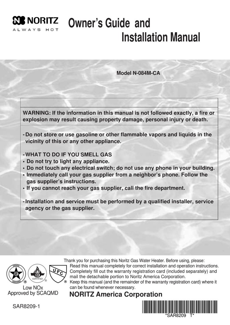
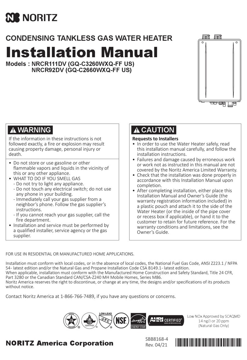
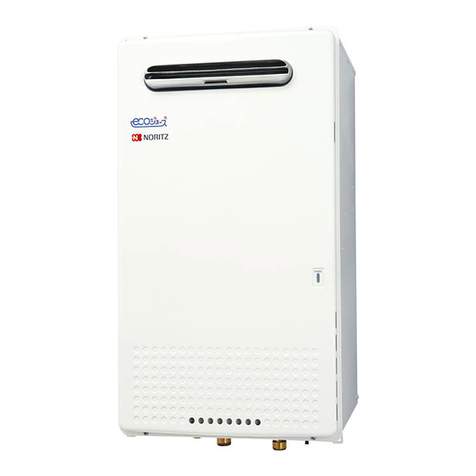
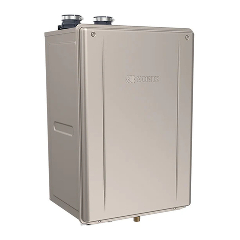
  9. Noritz NR501 Series Use and care manual

Noritz NR501 Series Use and care manual

This manual suits for next models

3

Other Noritz Water Heater manuals

Noritz NR98SVNG User manual

Noritz

Noritz NR98SVNG User manual

Noritz NR662-OD User manual

Noritz

Noritz NR662-OD User manual

Noritz NCC199CDV User manual

Noritz

Noritz NCC199CDV User manual

Noritz N-0751M-OD User manual

Noritz

Noritz N-0751M-OD User manual

Noritz NRCP1112-DV User manual

Noritz

Noritz NRCP1112-DV User manual

Noritz NCC199-SV User manual

Noritz

Noritz NCC199-SV User manual

Noritz pro TOUGH NR981-OD User manual

Noritz

Noritz pro TOUGH NR981-OD User manual

Noritz NC380-SV-ASME User manual

Noritz

Noritz NC380-SV-ASME User manual

Noritz NR50-OD User manual

Noritz

Noritz NR50-OD User manual

Noritz N-0631S User manual

Noritz

Noritz N-0631S User manual

Noritz N-0751M User manual

Noritz

Noritz N-0751M User manual

Noritz N-0841MC User manual

Noritz

Noritz N-0841MC User manual

Noritz NC250-SV-ASME User manual

Noritz

Noritz NC250-SV-ASME User manual

Noritz NRC661-DV User manual

Noritz

Noritz NRC661-DV User manual

Noritz NR83-DVC User manual

Noritz

Noritz NR83-DVC User manual

Noritz N-084 Programming manual

Noritz

Noritz N-084 Programming manual

Noritz NRC98-DV User manual

Noritz

Noritz NRC98-DV User manual

Noritz N-0931M-ASME User manual

Noritz

Noritz N-0931M-ASME User manual

Noritz NRC98-OD User manual

Noritz

Noritz NRC98-OD User manual

Noritz NCC300OD User manual

Noritz

Noritz NCC300OD User manual
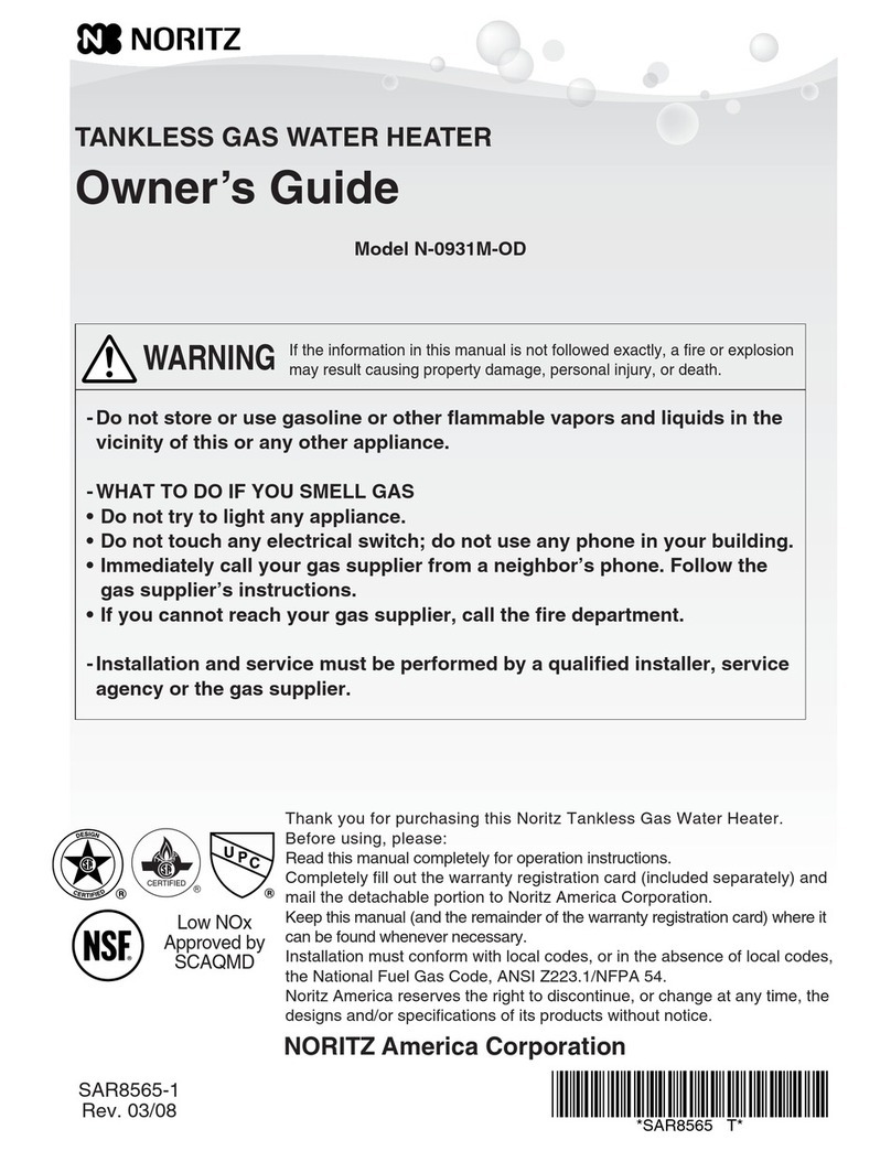
Noritz NR98-OD-NG User manual

Noritz

Noritz NR98-OD-NG User manual

Noritz N-063S User manual

Noritz

Noritz N-063S User manual

Noritz ecoTOUCH NRC111-DV-LP User manual
Noritz

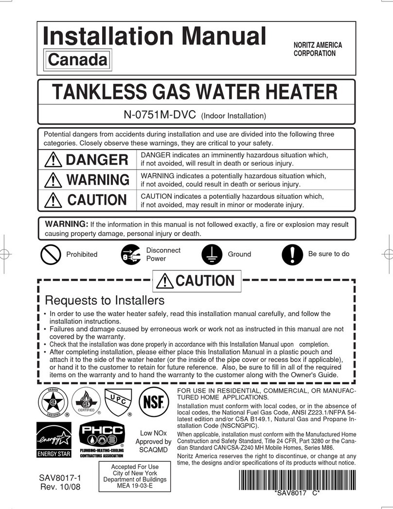
Noritz ecoTOUCH NRC111-DV-LP User manual

Noritz NCC1991-OD User manual

Noritz

Noritz NCC1991-OD User manual

Popular Water Heater manuals by other brands

clage German pool CEX13 operating instructions

clage

clage German pool CEX13 operating instructions

DeDietrich KALIKO TWH 200 EV Installation and service manual

DeDietrich

DeDietrich KALIKO TWH 200 EV Installation and service manual

veito FLOW Installation and operating instructions

veito

veito FLOW Installation and operating instructions

ICI Caldaie COSMOGAS AGUATANK 150 Instructions for installation, use and maintenance manual

ICI Caldaie

ICI Caldaie COSMOGAS AGUATANK 150 Instructions for installation, use and maintenance manual

Savio Laser 11 A Instruction manual for installation and use

Savio

Savio Laser 11 A Instruction manual for installation and use

Kenmore 153.582400 Use & care guide

Kenmore

Kenmore 153.582400 Use & care guide

STIEBEL ELTRON Eltronom SHU 5 S Operating and installation instructions

STIEBEL ELTRON

STIEBEL ELTRON Eltronom SHU 5 S Operating and installation instructions

clage E-Mini Series Operating and installation instructions

clage

clage E-Mini Series Operating and installation instructions

Solar SunX 317365-002 instruction manual

Solar

Solar SunX 317365-002 instruction manual

Bradford White EF Series Service manual

Bradford White

Bradford White EF Series Service manual

Dimplex ECSd125-580 Installation and user instructions

Dimplex

Dimplex ECSd125-580 Installation and user instructions

Dux 32FCR6N installation manual

Dux

Dux 32FCR6N installation manual

TESY GCV7/4S 10047 Instructions for use and maintenance

TESY

TESY GCV7/4S 10047 Instructions for use and maintenance

A.O. Smith Gphe 50 instruction manual

A.O. Smith

A.O. Smith Gphe 50 instruction manual

Rinnai REP199i Installation and operation manual

Rinnai

Rinnai REP199i Installation and operation manual

Toyotomi Oil Miser OM-148 (Type D) Operation and maintenance instructions

Toyotomi

Toyotomi Oil Miser OM-148 (Type D) Operation and maintenance instructions

Koryo KWHZF15Y user manual

Koryo

Koryo KWHZF15Y user manual

Pentair PSC-14-4-02 Installation and operation manual

Pentair

Pentair PSC-14-4-02 Installation and operation manual

manuals.online logo
manuals.online logoBrands
  • About & Mission
  • Contact us
  • Privacy Policy
  • Terms and Conditions

Copyright 2025 Manuals.Online. All Rights Reserved.

SKJ70NL
Rev. 10/13
NR501-OD, NR662-OD
This instructi nal manual is nly intended f r use by a qualified service pr fessi nal r auth rized N ritz
NR501, NR662 Series Heat Exchanger
Replacement
M del Include:
Page 1
N ritz America C rp rati n
11160 Grace Avenue, F untain Valley, CA 92708
Ph ne 866-766-7489 Fax 714-241-1196
Service Representative. Any unauth rized use f this manual may result in v iding the warranty.
Please c ntact N ritz Technical Supp rt (866-766-7489) f r additi nal supp rt.
NR501-OD, NR662-OD Series Heat Exchanger Replacement Pr cedure
Diagram
1.
(1) Disc nnect electrical p wer t unit
(2) Turn ff gas and water
(3) Rem ve 4 screws
(4) Rem ve drain 2 valves and drain the unit c mpletely
(5) Rem ve the c ver - circuit b ard
2.
(1) Disc nnect the c nnect rs fr m the circuit b ard
(2) Rem ve 2 gr und wires
(3) Rem ve the circuit b ard; there is a screw n middle-
upper f the circuit b ard. Let the circuit b ard hang
utside f the unit
3.
(1) Unplug Flame R d and Igniti n Plug
(2) L sen the cable tie and unplug the freeze preventi n
heater, thermal fuse (2)
(3) Unplug the high limit switch and the thermist r - heat
exchanger
(4) Unplug all wires that attach t the wiring harness
except water serv - main
Page 2
Unplug all wires that attach t the wiring harness and the
b dy f water heater
Pr cedure
Rem ve the fr nt c ver
Disc nnect the c nnect rs fr m the circuit b ard and
rem ve the gr und wire, and the circuit b ard
(4)
(1)
(2)
C ver - Circuit B ard
(3)
Water Serv - Main
NR501-OD, NR662-OD Series Heat Exchanger Replacement Pr cedure
Diagram
4.
(1) Rem ve 3 big silver screws n the manif ld plate that
attach the manif ld t the burner
(2) Rem ve 2 smaller silver screws fr m the manif ld
plate that attach the manif ld t the gas valve
(3) Rem ve manif ld plate and unplug the c nnect r
fr m gas s len id valves (3)
5.
(1) Rem ve "C" Clamp (3)
(2) Rem ve the water fl w sens r
Page 3
Pr cedure
Rem ve the manif ld plate
Disc nnect pipes fr m the water fl w sens r and the water
serv - main
(1)
(1)
(2)
Water Fl w Sens r
(2)
(3)
NR501-OD, NR662-OD Series Heat Exchanger Replacement Pr cedure
Diagram
6.
(1) Rem ve the 2 set screws n the b tt m f the burner
(2) Rem ve the 2 set screws n the t p f the case
(supp rt b tt m f the assembly)
(3) C pper Heat Exchanger(CU HE), Burner, and Fan will
c me ut in ne secti n. Rem ve fr m the unit.
7.
(1) Rem ve 10 screws h lding the burner t the CU HE
(2) Separate the burner fr m the CU HE
8.
(1) The gasket n the fr nt f the exhaust b x
(2) Fr nt side: Freeze preventi n heater
(3) Left side: High limit switch and thermist r - heat
exchanger
*Replace new O Ring f r the thermist r - heat
exchanger
Page 4
Rem ve heat exchanger c mp nents fr m ld heat
exchanger and put n new heat exchanger
Pr cedure
Rem ve the heat exchanger fr m the case
Replacing the CU HE
(1)
(2)
(1)
(3)
(2)
NR501-OD, NR662-OD Series Heat Exchanger Replacement Pr cedure
Diagram
(4) Attach the thermal fuse and 6 clamps fr m 4 sides f
heat exchanger, See 4 views f the heat exchanger t
make sure the thermal fuse is r uted c rrectly
Page 5
Pr cedure
The end f insulati n tube(Black) and the
clamp n the left are lined up
Right side
Install the thermal fuse(White) inside f
the st pper
St pper
Back side
Keep the thermal fuse straight
Left side - 1
Left side - 2
Make sure t r ute the thermal
fuse as sh wn in the diagram t
the right (Left side - 1 & 2)
Fr nt side
NR501-OD, NR662-OD Series Heat Exchanger Replacement Pr cedure
Diagram
(5) Place the new freeze preventi n heater with ne that
was shipped in the heat exchanger kit.
Wrap the freeze preventi n heater ar und utlet pipe
fr m the CU HE as sh wn in diagrams
(6) Make sure t r ute the wire as sh wn
in the diagram (6)
9.
(1) Rem ve ld burner gasket and replace with new ne
10.
(1) Inlet t the CU HE
(2) Outlet fr m the CU HE
Page 6
Pr cedure
Place new O Rings n new CU HE
Replace gasket
(2)
(1)
(1)
(5)
(6)
Outlet Pipe
(6)
NR501-OD, NR662-OD Series Heat Exchanger Replacement Pr cedure
Diagram
11.
(1) Attach 10 screws ar und perimeter f the burner and
the CU HE
12.
(1) Secure the 2 set screws n the b tt m f the burner
(2) Secure the 2 set screws n the t p f the case
13.
(1) Maintain the high limit switch, the thermist r - heat
exchanger, the thermal fuse, and the freeze
preventi n heater as sh wn in diagram (1)
(2) Maintain wiring harness as sh wn in diagram (2)
(3) Insert the utlet pipe t the water serv - main and
attach "C" clamp
Insert the water fl w sens r t the inlet water
c nnecti n and attach "C" clamp.
And then insert the inlet pipe t the water fl w sens r
and attach "C" clamp.
Page 7
Rec nnect water c nnecti ns
Pr cedure
Reattach the burner and the CU HE
Replace the assembly back inside the case
(1)
(2)
(1)
(2)
(3)
NR501-OD, NR662-OD Series Heat Exchanger Replacement Pr cedure
Diagram
14.
(1) Plug the c nnect r t gas s len id valves (3) as right
diagram
(2) C nfirm that there is -ring bef re replace the
manif ld plate
(3) Replace the 2 smaller silver screws fr m the manif ld
plate that attach the manif ld t the gas valve
(4) Replace the 3 big silver screws n the manif ld plate
that attach the manif ld t the burner
(5) Hand tighten 5 screws equally
15.
(1) Replace drain 2 valves
(2) Turn n c ld water shut ff valve sl wly (check f r
leaks ar und “C” clamps)
(3) If y u get leaks shut ff water and re-secure “C”
Clamps
Page 8
Pr cedure
Check f r water leaks
Replace the manif ld plate
(4)
(2)
(1)
BK & BL
wire
O & BL
wire GY & BL
wire
(3)
NR501-OD, NR662-OD Series Heat Exchanger Replacement Pr cedure
Diagram
16.
(1) Plug all wires that attach t the wiring harness
(2) Tie wires by cable tie as right diagram
(3) Tie wires by cable tie as right diagram
(4) Put the all wires in the p siti n as sh wn
in diagram (4)
(5) Secure the gr und wire
Page 9
Pr cedure
Plug all wires that attach t the wiring harness and the b dy
f the water heater
(5)
(4)
(2)
Cable Tie
Water Fl w Sens r
Thermist r - Air
Thermist r - C ld Water
Thermist r - H t Water
(3)
Cable Tie
NR501-OD, NR662-OD Series Heat Exchanger Replacement Pr cedure
Diagram
(6) Replace the circuit b ard; secure the screw n middle-
upper f the circuit b ard.
Secure the gr und wire.
(7) Rec nnect the c nnect rs t the circuit b ard
(8) Plug the high limit switch and the thermist r - heat
exchanger
(9)
(10)
Plug the freeze preventi n heater, the thermal fuse (2)
and tie the wires by the cable tie
Plug Flame R d and Igniti n Plug.
Page 10
Pr cedure
Take ut all wires n the
utside f the line
(6)
C nfirm that the blue c nnect r is
disc nnected.
(10)
(9)
(8)
Push the yell w
c nnect r.
Left side
Right side