North American Cable Equipment IP-POE24M Assembly instructions

IP-POE24M Hardware Installation Manual

Table of Contents
- I -
Table of Contents
Chapter 1 IP-POE24M Switch .............................................................................................................................................. 1
1.1 Standard Configuration ......................................................................................................................................... 1
1.2 Characteristic Parameters of IP-POE24M............................................................................................................. 3
1.3 ROHS Description ................................................................................................................................................. 4
Chapter 2 Installation Preparation ........................................................................................................................................ 5
2.1 Cautions ................................................................................................................................................................ 5
2.2 Safety Advice......................................................................................................................................................... 5
2.2.1 Safety Principles ....................................................................................................................................... 5
2.2.2 Safety Notices ........................................................................................................................................... 5
2.2.3 Safety Principles for Live Working............................................................................................................. 6
2.2.4 Electrostatic Discharge Prevention ........................................................................................................... 6
2.3 Requirements for Common Locations................................................................................................................... 7
2.3.1 Environment .............................................................................................................................................. 7
2.3.2 Location Configuration Prevention............................................................................................................ 7
2.3.3 Cabinet Configuration ............................................................................................................................... 7
2.3.4 Power Requirements................................................................................................................................. 8
2.4 Installation Tools and Device ................................................................................................................................. 8
Chapter 3 Installing the IP-POE24M Switch ......................................................................................................................... 9
3.1 Installation Flow of IP-POE24M ............................................................................................................................ 9
3.2 Installing the Chassis of the Switch....................................................................................................................... 9
3.2.1 Installing the Machine Box on the Desk .................................................................................................. 10
3.2.2 Installing the Chassis on the Cabinet...................................................................................................... 10
3.3 Connecting the Port............................................................................................................................................. 10
3.3.1 Connecting the Console Port .................................................................................................................. 10
3.3.2 Connecting Fast-Ethernet Interface ........................................................................................................ 12
3.3.3 Connecting the 1000M Ethernet Port...................................................................................................... 14
3.4 Checking After Installation................................................................................................................................... 16
Chapter 4 Maintaining the Switch....................................................................................................................................... 17
4.1 Opening the Chassis ........................................................................................................................................... 17
4.2 Closing Chassis................................................................................................................................................... 18
Chapter 5 Hardware Fault Analysis.................................................................................................................................... 19
5.1 Fault Separation .................................................................................................................................................. 19
5.1.1 Faults Relative with Power and Cooling System..................................................................................... 19
5.1.2 Faults Relative with Port, Cable and Connection.................................................................................... 19
5.2 Indicator Description............................................................................................................................................ 19
IP-POE24M Hardware Installation Manual
- 1 -
Chapter 1 IP-POE24M Switch
This document describes the characteristics and parameters of the IP-POE24M and
gives an overview of IP-POE24M physical interfaces.
1.1 Standard Configuration
The accessory ports of the IP-POE24M is composed of 24 fast-Ethernet ports, four
1000M optical/electrical ports and one console port. See table 1-1.
Table 1-1 Attributes of the necessary port
Port
Attribute
fast-Ethernet POE port
An port, which has a 10/100M auto-adaptation,
MDI/MDIX auto-identification for cable,
UTP(RJ45) port and the LINK/ACT 100Mbps
indicators. Each fast-Ethernet port has the POE
function. Each port can provide the outside up to
30W power consumption and the total power
consumption reaches 400W.
1000M optical/electrical port
Electrical port: 10/100/1000M auto-adaptation,
MDI/MDIX auto-identification of cable, UTP(RJ45)
port and the LINK/ACT indicators
SFP port: having LINK/ACT indicators
Console port
An RJ45 port with a rate of 9600 bps
Additionally, IP-POE24M has a grounding column, a socket and a power switch at its
rear panel.
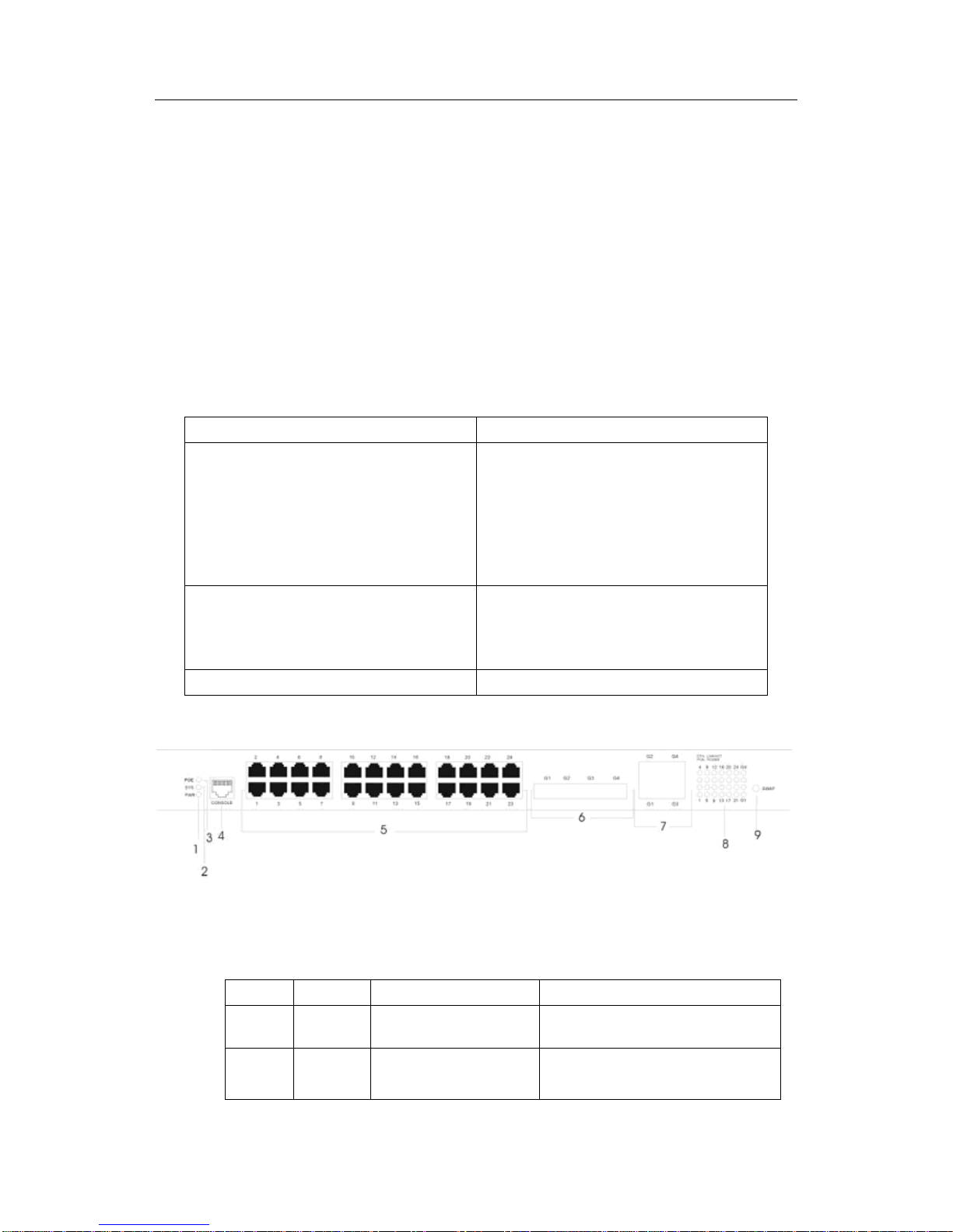
Figure 1-1 Front template of the IP-POE24M switch
Table 1-2 Parts at the front template of the IP-POE24M switch
No.
Abbrev.
Name
Description
1
PWR
Power indicator
If the switch is powered on, the indicator
is on.
2
SYS
System indicator
If the indicator is always on, the system
is being started.

IP-POE24M Hardware Installation Manual
- 2 -
If the indicator flickers, the system works
normally.
3
POE
POE指示灯POE indicator
If the POE indicator is on, it means that
24 indicators on the right side show the
state of the POE port.
4
CONSOLE
Console port
Manages the switch locally.
5
1-24
24 electrical port with the
POE function
Forward the 10/100M Ethernet electrical
signals and provide POE function.
Their peers can be connected to the PD
devices which satisfy the IEEE 802.3af
standard.
6
G1-G4
Gigabit-Ethernet optical
port
Forwards the 1000M Ethernet optical
signals.
7
G1-G4
Gigabit-Ethernet electrical
port
Forwards the 10/100/1000M Ethernet
electrical signals.
8
LINK/ACT
Normal mode of the
indicator: indicating the
LINK/ACT state of each
port
POE mode of the indicator:
indicating the POE power
supply state of each port
Normal mode:
If the indicator is always on, the link on
the port is normal.
If the indicator flickers, the data is
received or transmitted through the port.
POE mode:
If the indicator is always on, the port is
powered through the POE mode.
If the indicator is off, the port is not
supplied with power.
9
SWAP
A shift key for exchanging
the normal mode with the
POE mode of the indicator
If you press the shift key in normal
mode, the indicator will enter the POE
mode. If you press again, the indicator
will enter the normal mode again.
If you leave the key alone for 30
seconds in POE mode, the indicator
automatically enters the normal mode.
Figure 1-2 Rear template of the IP-POE24M switch

IP-POE24M Hardware Installation Manual
- 3 -
Table 1-3 Parts at the rear template of the IP-POE24M switch
No.
Abbrev.
Name
Description
1
None
Grounding
column
Properly ground the system.
2
None
Power switch
ON means activating power, while
OFF means disabling power.
3
None
AC power socket
AC100-240V
1.2 Characteristic Parameters of IP-POE24M
Protocol standard
IEEE 802.1d Spanning Tree Protocol
IEEE 802.1p Class of Service
IEEE 802.1q tagged VLAN
IEEE 802.3x Flow control
IEEE 802.3ad Link aggregation
IEEE 802.3af standard
Network management
standard
RFC 1157 SNMP v1/v2
RFC 1213 MIB II
RFC 1757 RMON 1,2,3,9
Memory
EPROM: 512k Bytes
Flash Memory: 8M Bytes
SDRAM: 64Mbytes
Standard configuration
24 10/100Base-TX ports
One Console port
Four fixed 1000M optical/electrical Ethernet ports
Specifications
442.50*315.00*44mm
Working
temperature/humidity
0℃-60℃; 10%-85% no condensation
Storage temperature/
humidity
-40℃-80℃; 5%-95% no condensation
AC power supply
Input voltage: AC100-240V
Input frequency: 47-63Hz
Input current: 5A/230V
Power consumption
Up to 400W
Table of contents
Popular Switch manuals by other brands

SMC Networks
SMC Networks SMC6224M Technical specifications

Aeotec
Aeotec ZWA003-S operating manual

TRENDnet
TRENDnet TK-209i Quick installation guide

Planet
Planet FGSW-2022VHP user manual

Avocent
Avocent AutoView 2000 AV2000BC AV2000BC Installer/user guide

Moxa Technologies
Moxa Technologies PT-7728 Series user manual

Intos Electronic
Intos Electronic inLine 35392I operating instructions

Cisco
Cisco Catalyst 3560-X-24T Technical specifications

Asante
Asante IntraCore IC3648 Specifications

Siemens
Siemens SIRIUS 3SE7310-1AE Series Original operating instructions

Edge-Core
Edge-Core DCS520 quick start guide

RGBLE
RGBLE S00203 user manual


