North Shore Safety EVSE 2 User manual
EVSE 2 Charging Station
7335 Production Drive Mentor, OH 44060 Phone: 440-205-9188 Fax: 440-205-9187 [email protected] www.nssltd.com

Table of contents
1 Introduction .................................................................................................................................................................. pg. 3
2 Important Safety Warnings and Cautions .................................................................................................................... pg. 4
3 Regulatory Information ................................................................................................................................................ pg. 4
3.1 Regulatory Information .......................................................................................................................................... 4
3.2 Product Specication ............................................................................................................................................. 4
3.3 Radio and Television Interference .......................................................................................................................... 4
4 Features and Specications ......................................................................................................................................... pg. 4 - 5
4.1 Ground Fault Protection ......................................................................................................................................... 4
4.2 Automatic Reset ..................................................................................................................................................... 4
4.3 Ground Assurance Monitoring ................................................................................................................................ 4
4.2 Self-Testing ............................................................................................................................................................. 4
4.4 Features and Specications Charts ........................................................................................................................ 4
5 Applicable Electrical Systems ....................................................................................................................................... pg. 6-7
5.1 Applicable Electrical Systems ................................................................................................................................. 6
5.2 Electrical Requirements .......................................................................................................................................... 7
5.3 Grounding Instructions ............................................................................................................................................ 7
6 Amperage and Breaker Parameters ............................................................................................................................. pg. 8
7 Mounting Instructions .................................................................................................................................................... pg. 8-14
7.1 Package contents ................................................................................................................................................... 8
7.2 Tool for Package Contents ...................................................................................................................................... 8
7.3 Finished Wall Installation ......................................................................................................................................... 9-11
7.4 Masonry Wall Installation .........................................................................................................................................12-13
7.5 Mounting Template .................................................................................................................................................. 14
8 Power and Status LED Indications ................................................................................................................................ pg. 15-16
9 Troubleshooting ............................................................................................................................................................. pg.16
10 Miscellaneous ..............................................................................................................................................................pg.17
10.1 Maintennance ........................................................................................................................................................ 17
10.2 Cleaning ................................................................................................................................................................ 17
10.3 Storage and Moving .............................................................................................................................................. 17
11 Warranty ...................................................................................................................................................................... pg.17
Installation and Operating Instructions | North Shore Safety EVSE2 Series Charging Station | 2
page 2

Installation and Operating Instructions | North Shore Safety EVSE2 Series Charging Station | 3
11IntroductionIntroduction
The EVSE2 Charging Station is designed for the North Ameri-
can market to charge plug-in electric vehicles (PHEV) and
battery electric vehicles (BEV).
This document provides instructions for the EVSE2 Charging
Station and is not for use for any other product. Before instal-
lation or use of this product, you should review this manual
carefully and consult with a licensed contractor, licensed
electrician, or trained installation expert to ensure compliance
with building codes and safety standards.
2 Important Safety Warnings2 Important Safety Warnings
and Cautionsand Cautions
Please read and follow these safety Warnings and Cautions
carefully before operating the EVSE2 Charging Station.
Failure to follow these instructions may result in serious
injury or property damage.
►When using electrical products, basic precautions
should always be followed, including the following.
This manual contains important instructions for
model VSSM - 232NA25 that shall be followed during
installation, operation, and maintenance of the unit.
►Read all the instructions before using this product.
►Children should be supervised when this product is
used around children.
► Do not put ngers into the EVSE2 connector.
► Do not install the EVSE2 near ammable, explosive,
or combustible materials. Do not locate or store
ammable, explosive, or combustible materials near
the EVSE2.
► Do not use this product if the exible power cord or
EVSE2 cable are frayed, have broken insulation, or
display any other signs of damage.
►Do not use this product if the enclosure or the
EVSE2 connector is broken, cracked, open, or show
any ther signs of damage.
►The EVSE2 contains no user-serviceable parts. Do
not attempt to open, repair, or service the EVSE2
yourself. Do not attempt access to the internal com-
ponents of the EVSE2 unit in any way. Do not tamper
with any of the product labeling and/or the clear
back overlay that is meant for North Shore Safety
technical maintenance personnel only. If the EVSE2
requires servicing, contact North Shore Safety.
SAVE THESE INSTRUCTIONS!SAVE THESE INSTRUCTIONS!
CAUTIONSCAUTIONS
►Disconnect main service power to the EVSE2 before
cleaning the unit. Do not use cleaning solvents to clean
any part of the EVSE2. Clean enclosure, cable, and
connector with a clean, dry cloth to remove dust and
dirt accumulation.
►Disconnect main service supply or unplug unit to
achieve electrical isolation.
►If the EVSE2 fails to operate correctly in accordance
with the operation manual, do not use this device.
Contact North Shore Safety for repair or replacement.
►Improper installation of the EVSE2 can result in
personal injury or product damage.
►This EVSE2 installation guide is not a substitute for
electrical safety precautions.
► Use this EVSE2 within the specied operating
parameters. Failure to do so may result in injury or
death.
►Locate and install this EVSE2 in a location where the
charge cable will not be stepped on, tripped over, or
subject to damage or stress.
►The EVSE 2 must be connected to a grounded, metal,
permanent wiring system, or an equipment-grounding
conductor must be run with the circuit conductors and
connected to the equipment-grounding terminal on the
EVSE2.
►DO NOT USE AN EXTENSION CORD ON THE EVSE2.
This can cause a shorting or over-heating condition
that could lead to injury or death.
►Incorrect installation of the EVSE2 can result in
damage to the vehicle’s battery and to the EVSE2 itself.
These damages will void the warranty for the vehicle and
the EVSE2.
►Do not operate the EVSE2 in temperatures beyond its
operating range of -31°F to +122°F (-35°C to +50°C).
!
WARNINGSWARNINGS
!
page 3

Installation and Operating Instructions | North Shore Safety EVSE2 Series Charging Station | 4
33Regulatory InformationRegulatory Information
3.1 Regulatory Information3.1 Regulatory Information
At the end of service life, the EVSE2 should be recycled
according to local laws and regulations.
3.2 Product Specication3.2 Product Specication
All EVSE2 specications and descriptions are accurate at the
time of this document’s printing. We always strive to constantly
improve and update our products. North Shore Safety reserves
the right to make changes at any time, without notice and
without obligation.
3.3 Radio and Television Interference3.3 Radio and Television Interference
The equipment described in this manual has been designed to
protect against Radio Frequency Interference (RFI). However,
there are some instances where high-powered radio signals or
nearby RF-producing equipment (such as digital phones, RF
communications equipment, etc.) could aect EVSE2 oper-
ations. If interference to the EVSE2 occurs during charging,
contact North Shore Safety.
4 Features and Specications
The EVSE2 includes ground-fault protection, automatic
reset upon grid power loss, ground assurance monitoring, and
self-testing capabilities. Manual resetting of the EVSE2 is not
necessary.
4.1 Ground Fault Protection
Continually provides a safe power supply to the vehicle. If a
ground fault is present, the EVSE2 detects it and cuts power
ow, protecting people and the vehicle from an electric shock
hazard.
4.2 Automatic Reset
If main line side power supply is interrupted during charging,
the EVSE2 will reset itself automatically and reattempt charging
after main line side power supply is restored.
If the problem is associated with a ground fault, the EVSE2
makes automatic reset attempts in sequential 15 second
periods. If the charging mode can not be restored, the
appropriate failure indication of a solid red. Status light will ap-
pear on the unit’s front panel.
See the Power and Status LED Indications Table (page 19).
The automatic reset feature ensures that your vehicle will be
charged and ready to use by automatically restoring power
after temporary interruptions (grid-power outages, temporary
ground faults, and power surges.
4.3 Ground Assurance Monitoring
A proper electrical ground is critical to reliable groundfault
protection. The EVSE2 includes a ground monitoring circuit to
assure presence of a safe electrical ground.
4.4 Self-Testing
To assure proper functionality and safety, the EVSE2 includes
self-testing and diagnostics circuitry, which is automatically
performed prior to each charging cycle. circuit to assure
presence of a safe electrical ground.
page 4

Installation and Operating Instructions | North Shore Safety EVSE2 Series Charging Station | 5
Ground Fault
Trip Level
18 mA (nominal; 20mA Max) (US)
Ground
Assurance
50K ohm Max (US), 120VAC-Earth
Ground Fault
Test
Automatic before each cycle (Firmware
controlled)
Ground Fault
Retry
Automatic retries at 15-sec intervals (per
UL2231-2)
Stop Charge Manual, 2 minute time-out
Master Clear For System Reset (Overrides Ground
Fault Retry and all other fault conditions)
Power
Indication
Amber LED
Charge
Status
Indicators
Amber (Ready)
Cyan (EV Plugged In)
Green/Blue Flashing (Charging)
Red Flashing (Fault) (see tables)
Ratings and
Agency
Approvals
Agency Approvals
Standard Compliances through a Na-
tional
Registered Testing Lab (NRTL)
North American (US) Operation
UL 2594 Ed. 2 (2016)
UL 2251
UL 2231-1 & -2 Ed. 2 (2016)
UL1998
SAE J1772
NEC Article 625 (2017)
Product FeaturesProduct Features Technical SpecicationsTechnical Specications
Voltage and
Wiring
(120V above
ground)
* 240VAC single-phase (US): L1, L2, and
safety ground.
*208VAC 3-phase, wye-connected (US):
Any 2 phases and safety ground.
* 240VAC 3-phase, delta-connected
(US):
with center tap on one leg. Use only the
two phases on either side of the center
tap. The two phases must both measure
120V AC to ground. Do not use the third
leg (208VAC to ground “stinger”)
Product Usage Unit must be properly secured to a
vertical surface and is rated for stationary
use only.
Dimensions &
Weight
Height = 9.0” (229mm)
Width = 7.3” (185mm)
Depth = 2.8” (71mm)
Cable Length = 25ft(7.6m) per NEC625
Weight = 12-lbs (5.4kg)
Input Voltage
Phase AC
175 VAC – 264 VAC and 60Hz
Output
Amperage
32A Max (model dependent)
Surge
Protection
6kV @ 3000A
Temperature
Storage
-40°F to +185°F (-40°C to +85°C)
Temperature
Operating
Humidity
-31°F to +122°F (-35°C to +50°C)
Up to 95% non-condensing
Enclosure NEMA 3R (rain-proof) & per UL 50E
page 5
Installation and Operating Instructions | North Shore Safety EVSE2 Series Charging Station | 6
5Applicable Electrical
Systems
5.1 Applicable US Systems
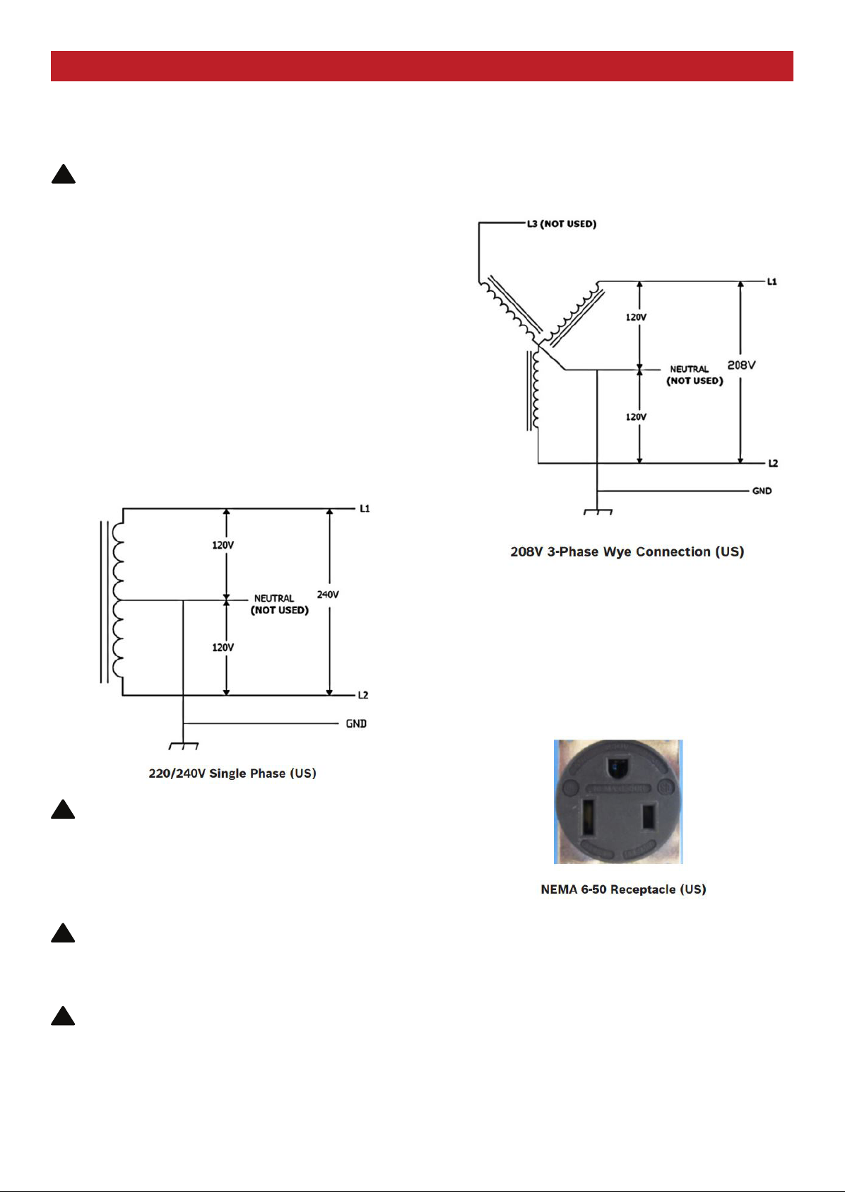
5.1.1 220/240V Single Phase Connection
IMPORTANT Identify the onsite service connectionIMPORTANT Identify the onsite service connection
before installing the EVSE2. If you are unsure of thebefore installing the EVSE2. If you are unsure of the
available service connection, consult the local utilityavailable service connection, consult the local utility
company.company.
DO NOT USE AN EXTENSION CORD ON THE EVSE2. ThisDO NOT USE AN EXTENSION CORD ON THE EVSE2. This
can cause a shorting or over-heating condition that couldcan cause a shorting or over-heating condition that could
lead to injury or death.lead to injury or death.
The L1, L2, and Ground outputs in the following illustrationsThe L1, L2, and Ground outputs in the following illustrations
correspond to the inputs on thecorrespond to the inputs on the EVSE2. For the (earth) ground. For the (earth) ground
connection, always connect the neutral at the service panel toconnection, always connect the neutral at the service panel to
earth ground. Ground fault protection is not possible unless theearth ground. Ground fault protection is not possible unless the
neutral (center tap on the service transformer) is connected toneutral (center tap on the service transformer) is connected to
an earth ground.an earth ground.
5.1.2 208V 3-Phase Wye Connection
Any two of the legs can be used to provide 208V to the EVSE2
with a Wye-connected secondary. For example, L1 and L2, or
L1 and L3, or L2 and L3. Reference the wiring diagram below.
5.1.3 Wall Receptacle Geometry
The drawing below represents the appropriate wall receptacle of
EVSE2 plugs-in. This receptacle is to be installed by a licensed
electrcian.
NOTE: A current-carrying neutral is not required for the
Charging Station for 208V connections.
WARNING: The EVSE2 is a single-phase device.WARNING: The EVSE2 is a single-phase device.
Do not connect all three phases of a 3-phase feed.Do not connect all three phases of a 3-phase feed.
Only three wires are connected (2 conductors andOnly three wires are connected (2 conductors and
1 ground). Take care that the service transformer1 ground). Take care that the service transformer
secondary connection is known and that the threesecondary connection is known and that the three
wires from the mainpanel circuit breaker arewires from the mainpanel circuit breaker are
correctly connected and labeled.correctly connected and labeled.
WARNING: The EVSE2 must be installed by aWARNING: The EVSE2 must be installed by a
licensed electrician and in accordance with alllicensed electrician and in accordance with all
local electrical codes, ordinances, and authoritieslocal electrical codes, ordinances, and authorities
having jurisdiction.having jurisdiction.
WARNING: Do not install the EVSE2 nearWARNING: Do not install the EVSE2 near
ammable, explosive, or combustible materials. ammable, explosive, or combustible materials.
Do not locate or store ammable, explosive, or Do not locate or store ammable, explosive, or
combustible materials near the EVSE2.combustible materials near the EVSE2.
!
!
!
!
page 6

Installation and Operating Instructions | North Shore Safety EVSE2 Series Charging Station | 7
5.2 Electrical Requirements
CAUTIONSCAUTIONS
CAUTIONSCAUTIONS
!
!
The AC electrical connection must have a grounded, dedicated
servicemain. No other loads shall be connected to the same
circuit. Use of a non-dedicated circuit could exceed the current
rating of the circuit breaker and cause it to trip or open.
Do not use portable or stationary backup generating equipment
to charge the vehicle. This may cause damage to the vehicle’s
charging system. Only charge the vehicle from utility-supplied
power.
5.3 Grounding Instructions
WARNING: This product must be grounded. If itWARNING: This product must be grounded. If it
should malfunction or break down, groundingshould malfunction or break down, grounding
provides a path of least resistance for electricprovides a path of least resistance for electric
current to reduce the risk of electric shock. Thiscurrent to reduce the risk of electric shock. This
product is equipped with a cord having anproduct is equipped with a cord having an
equipment grounding conductor and a groundingequipment grounding conductor and a grounding
plug. The plug must be plugged into an appropriateplug. The plug must be plugged into an appropriate
outlet that is properly installed and grounded inoutlet that is properly installed and grounded in
accordance with all local codes and ordinances.accordance with all local codes and ordinances.
WARNING: Improper connection of the equipmentWARNING: Improper connection of the equipment
grounding conductor is liable to result in a risk ofgrounding conductor is liable to result in a risk of
electric shock. Check with a qualied electrician or electric shock. Check with a qualied electrician or
serviceman if you are in doubt as to whether theserviceman if you are in doubt as to whether the
product is properly grounded. Do not modify theproduct is properly grounded. Do not modify the
plug provided with the product; if it will not t the plug provided with the product; if it will not t the
outlet, have a proper outlet installed by a qualied outlet, have a proper outlet installed by a qualied
electrician.electrician.
!
!
page 7

Installation and Operating Instructions | North Shore Safety EVSE2 Series Charging Station | 8
6 Amperage and Breaker
Parameters
7Mounting Instructions
The EVSE2 has been factory set at an output current setting of
4 for Table 1 and 5 for Tables 2 and 3. For all other amperages,
changes to output amperage may be made by a qualied
electrician as follows:
1. Unplug the EVSE2 from the wall outlet and turn power o to
the outlet at the breaker panel.
2. Remove the adhesive overlay from the molded well on the
back of the EVSE2.
3. Using a small at-blade screwdriver, set the current-adjust-
ment selector to the applicable output current-limiting setting
indicated in the appropriate table below.
NOTE:
1. North American current setting is 30A (setting 4). This
setting is NOT to be exceeded. Settings of 30A or less
(settings 1-4) only are permitted on North American
models.
2. Adhesive overlay must be replaced securely to the
molded well to preserve the EVSE2’s environmental ratings
and warranty.
Table-1 - North American Current Adjustment Settings
Current Adjustment
Selector Setting
Output
(Amps)
Corresponding Breaker
Required
1 12 15
2 16 20
3 24 30
4 32 40
5 32 40
7.1 Package Contents
►(1)EVSE2 Series Charging Station
►(1)EVSE2 Series Charging Station hardware kit:
(2) #8 x 1-1/4” Pan-head Screws (for EVSE2 stud-mount
applications)
(2) 3/16” x 1-1/4” (5mm) Tapered-head Masonry
Screws (for EVSE2 masonry-mount applications)
►(1) EVSE2 Cord-set Hanger
►EVSE2 Cord-set Hanger hardware kit:
(2) Cord-set Hanger Spacers
(2) #10 x 2-1/2” Philips Black-oxide Screws (for Cordset
Hanger stud-mount applications)
(2) 3/16”(5mm) x 2-1/4” Flat-head Philips Masonry
Screws (for Cord-set Hanger masonry-mount applications)
7.2 Tools Required for Package Contents
►(1)EVSE2 Series Charging Station
►(1)EVSE2 Series Charging Station hardware kit:
(2) #8 x 1-1/4” Pan-head Screws (for EVSE2 stud-mount
applications)
(2) 3/16” x 1-1/4” (5mm) Tapered-head Masonry
Screws (for EVSE2 masonry-mount applications)
►(1) EVSE2 Cord-set Hanger
►EVSE2 Cord-set Hanger hardware kit:
(2) Cord-set Hanger Spacers
(2) #10 x 2-1/2” Philips Black-oxide Screws (for Cordset
Hanger stud-mount applications)
(2) 3/16”(5mm) x 2-1/4” Flat-head Philips Masonry
Screws (for Cord-set Hanger masonry-mount applications)
page 8

Installation and Operating Instructions | North Shore Safety EVSE2 Series Charging Station | 9
7.3 Finished Wall Installation
Ideally, the EVSE2 should be mounted to the studs of a drywall/wood-stud structure, or to a
masonry-wall. For a drywall / wood-stud structure the EVSE2 is specically designed to be secured
to the studs. This is the reason the two mounting
slots are designed into the EVSE2’s back mounting surface in a centered, vertical in-line
conguration (not unlike that of a standard multi-plug power-strip).
1. Using a stud nder, locate the desired mounting points for the EVSE2’s two (2) mounting
screws (denoted on the template with the symbols), and draw a vertical line to mark the stud
site.
2. Using adhesive tape, secure the mounting template (included on page 18 of this manual) to the
desired mounting location wall surface. Mount the template at a height of 45” from the oor to
the bottom of the template.
WARNING: Read all instructions before installing the EVSE2WARNING: Read all instructions before installing the EVSE2
!
page 9

Installation and Operating Instructions | North Shore Safety EVSE2 Series Charging Station | 10
3. Using a 1/8” (3-mm) drill bit, drill 2-holes at the target-points on the template. These two points
are vertically located with reference to each other (they are also 4.9 in [125-mm] apart).
4. Install two (2) #8 pan-head screws to the screw holes; drive these screws leaving a 0.40” space
from the top of the screw head to the wall surface. This will provide the proper spacing required
for the mounting slots on the back of the unit.
page 10

5. Align the EVSE2 to the mounting screws and gently slide the unit down to secure it within the
rear mounting slots. Plug the EVSE2 into the appropriate, existing power receptacle.
NOTE: The EVSE2 has 4 radiased corner standos
that must be touching the wall-mounting surface to
assure stability. Tighten the 2 mounting screws as
needed to accomplish this.
Installation and Operating Instructions | North Shore Safety EVSE2 Series Charging Station | 11
page 11

2. Using a 1/8” (3-mm) masonry drill bit, drill 2-holes at the target-points (denoted with the symbol)
on the template.
These two points are vertically located with reference to each other. (They are also 4.9 in [125-
mm] apart.)
Installation and Operating Instructions | North Shore Safety EVSE2 Series Charging Station | 12
7.4 Masonry Wall Installation7.4 Masonry Wall Installation
1. Using adhesive tape, secure the mounting template (included on page 18 of this manual) to the
desired mounting location on the wall surface. Mount the template at a height of 45” from the
oor to the bottom of the template.
page 12

Installation and Operating Instructions | North Shore Safety EVSE2 Series Charging Station | 13
3. Remove the template from the wall and install two (2) 3/16” (5-mm) tapered-head masonry
screws. Drive these screws leaving a 1/2” space from the top of the screw head to the wall
surface. This will provide the proper spacing required for the mounting slots on the back of the
unit.
4. Align the EVSE2 to the mounting screws and gently slide the unit down to secure it within the
rear mounting slots.Plug the EVSE2 into the appropriate, existing power receptacle.
NOTE: The EVSE2 has 4 radiased corner standos
that must be touching the wall-mounting surface to
assure stability. Tighten the 2 mounting screws as
needed to accomplish this.
page 13

Installation and Operating Instructions | North Shore Safety EVSE2 Series Charging Station | 14
7.5 Mounting Template7.5 Mounting Template
page 14

Installation and Operating Instructions | North Shore Safety EVSE2 Series Charging Station | 15
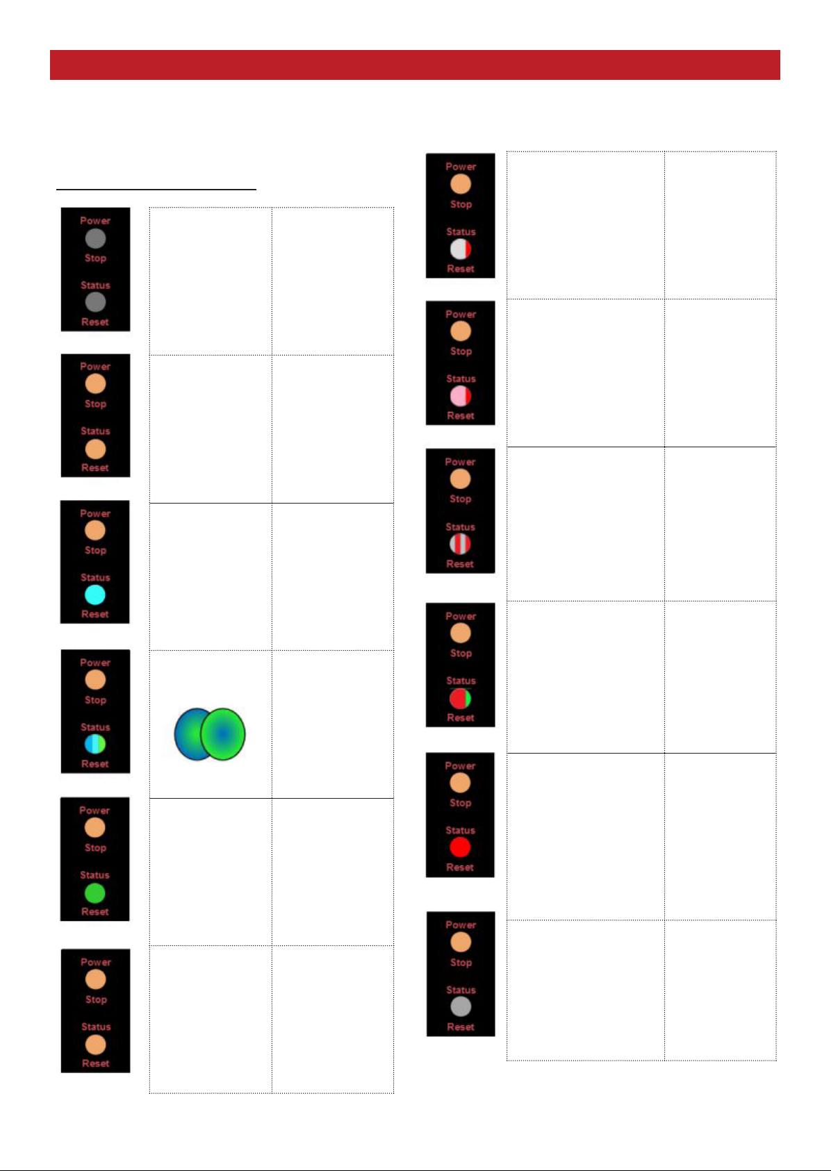
8 Power and Status LED Indications8 Power and Status LED Indications
Operating Instructions - Power and Status LED IndicationsOperating Instructions - Power and Status LED Indications
Normal standby
indication, both
lights are amber.
EVSE2 Status - Vehicle not coupled.
EVSE2 Status - Vehicle has just coupled; systems communicate desired power; beginning (or ending) of charging
EVSE2 Status - Normal charging operation
EVSE2 Status - Manual end of charge to uncouple
Power on, status light is
cyan.
This indicates a normal
start or stop of the charging
sequence between the
EVSE2 and the vehicle.
Power on, status light is a slow
blue/green transition.
Normal charging in progress
Charging completes
automatically or when the stop
button is pressed
After pressing the power/stop
button, a stready blue indicator
lights for a 2-minute period
during which the vehicle can
be uncoupled. If the coupler is
latched, press the stop button
again.
Once uncoupled, both indica-
tors turn to standby.
Charging resumes automatically, with vehicle
request, if power is lost and restored.
See advanced details of operation on the
following page.
Power on, status light is
green.
This indicates either that
charging has completed or
that the vehicle has decided
to delay charging.
Apply AC power. If Status light blinks red,
uncouple vehicle and press the reset
button to begin self test. If the error
persists, there may be an AC power
problem such as incorrect voltage,
grounding, or polarity. For safety, turn o
AC breaker at panel, uncouple vehicle if
connected; contact a service
professional. Do not re-power.
page 15
Installation and Operating Instructions | North Shore Safety EVSE2 Series Charging Station | 16
Power and Status LEDPower and Status LED
Indications (cont’d)Indications (cont’d)
9 Troubleshooting9 Troubleshooting
Normal Charging SequenceNormal Charging Sequence
Supply power is o Indicators are dark
Supply power is on;
no vehicle
connected
Both indicators are
stready amber
Vehicle connects;
system normal;
EVSE2
communicates...
Status indicator is
cyan
Normal charging Color alternates
blue/green
Charge completed Stready green;
Supply power is on;
vehicle
disconnected
Sready amber
Connection to vehicle
unsatisfactory.
First, press reset button
on EVSE2.
If needed, then try re-
moveing and re-inserting
coupler to vehicle
Short red ash
EVSE2 over-heated (this
may be caused ambient
temperature
exceeding 50C (122F).
After cooling system may
restart
Dim red; bright
red ash
Safety ground not detect-
ed (do not touch vehicle)
or wrong supply voltage
detected
Suppy power must be
disconnected at discon-
nect or breaker before
servicing
Fast-blinking red
Momentary fault - EVSE2
retries automatically in 16
seconds
Red; short green
ash
GROUND FAULT or
system failure,
Remove coupler then
press EVSE2 reset button
Otherwise, supply power
must be diconnected at
disconnect or breaker
Stready red
Remove coupler then
press EVSE2 reset button
EVSE2 failure
Otherwise, supply power
must be disconnected
at disconnect or breaker
before servicing
Indicator dark
page 16

Installation and Operating Instructions | North Shore Safety EVSE2 Series Charging Station | 17
10 Miscellaneous10 Miscellaneous
10.1 Maintenance10.1 Maintenance
WARNING: Do not attempt to service the EVSE2.WARNING: Do not attempt to service the EVSE2.
The EVSE2 has no user-serviceable components.The EVSE2 has no user-serviceable components.
CAUTIONCAUTION
CAUTIONCAUTION
!
!
!
If the unit is not operating properly, contact North Shore Safety
at 1-877-4SAFE4U (472-3348) for assistance. The EVSE2
requires no scheduled maintenance, only periodic cleaning.
Always be sure to return the charging cable and coupler to
its proper storage area to avoid potential damage to the
unit and to prevent potential trip hazards.
Regularly inspect the EVSE2 unit and charging cable for
signs of damage. If the EVSE2 unit or charging cable are
damaged, contact North Shore Safety for service or repair.
10.2 Cleaning10.2 Cleaning
10.3 Storage and Moving10.3 Storage and Moving
Always turn o service power (supply-side power at the main
service panel) before cleaning the EVSE2 and/or charging
cable.
Never use cleaning solvents, abrasive powders/liquids or
scouring pads to clean the EVSE2 and cable/coupler.
Clean the EVSE2 unit and cable/coupler with a soft damp
or dry cloth to remove dust or dirt.
Unit storage temperature range: -40°F to +185°F (-40°C to
+85°C) . When transporting the EVSE2 unit, do not carry by
only the plug or by the charging cable.
Contact North Shore Safety for EVSE2 relocation or storage
requirements at 1-877-4SAFE4U (472-3348).
11 Warranty11 Warranty
North Shore Safety warrants to the consumer its Line-Gard
products to be free from defects in materials and workmanship,
under normal use and service, for a period of two years from
date of purchase. North Shore Safety, at its option, will repair or
replace the defective products without charge within 2-years of
the date of the product’s purchase
provided that the defect occurred during normal use. The
defective unit must be returned freight prepaid, with a RGA
(Returned Goods Authorization) including a description of the
problem, and a proof of purchase date to the Quality Assurance
Dept. North Shore Safety, Ltd. 7335 Production Drive, Mentor,
OH 44060.
North Shore Safety will not be liable, directly or indirectly, for
installation or removal of this device, or for any personal injury,
or property damages, or incidental, indirect, or consequential
damages of any kind, as a result of a defective device. The
exclusive remedy, under this warranty, is the repair or replace-
ment of the defective device. In no case shall North Shore
Safety’s liability exceed the purchase price. This warranty is void
or not covered if this device is found to be: not properly installed,
tampered with, not used according to label instructions and
ratings, enclosure breached (button cover label, conduit hubs,
vent, or lid fasteners), surged, short circuited, or abused.
page 17
Table of contents


