10
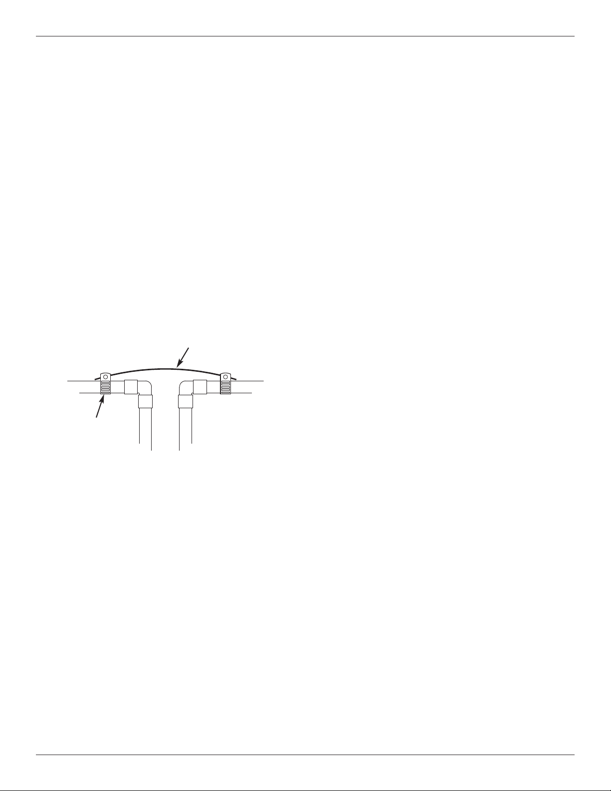
COLD WATER PIPE GROUNDING
CAUTION: The house cold water pipe (metal only)
is often used as a ground for the house
electrical system, The 3-valve bypass
type of installation, shown in Figure 8,
will maintain ground continuity. If you
use a plastic bypass valve at the unit,
continuity is broken. To restore the
ground, do the following:
1. Install a #4 copper wire across the removed section
of main water pipe, securely clamping it at both
ends (See Figure 14) - parts not included.
NOTE: Check local plumbing and electrical codes
for proper installation of the ground wire.
The installation must conform to them. In
Massachusetts, plumbing codes of
Massachusetts shall be conformed to.
Consult with your licensed plumber.
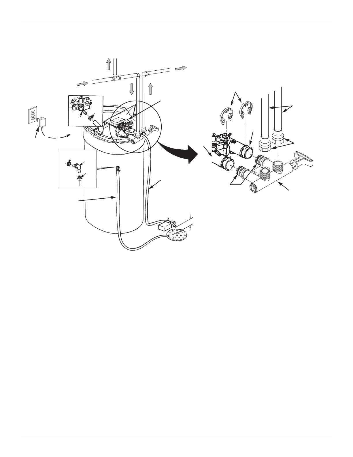
Installation Instructions
INSTALL VALVE DRAIN HOSE
NOTE: See valve drain options on pages 6 & 7.
1. Measure, cut to needed length and connect the 3/8”
drain line (provided) to the water softener valve
drain fitting. Use a hose clamp to hold the hose in
place.
IMPORTANT: If codes require a rigid drain line see
“Valve Drain requirements" section.
2. Run the drain hose (or a rigid line) to the floor drain.
Secure drain hose. This will prevent “whipping'' dur-
ing regenerations. Be sure to provide a 1-1/2”
minimum air gap to prevent possible sewer
water backup. See “Air Gap Requirements" sec-
tion.
NOTE: In addition to a floor drain, you can use a laun-
dry tub or standpipe as a drain point for this
hose. Avoid long drain hose runs, or elevating
the hose more than 8 feet above the floor.
FIG. 14
Ground
Wire
lamp (2)
1. Measure, cut to needed length and connect the 3/8”
drain line (provided) to the salt storage tank overflow
elbow and secure in place with a hose clamp.
2. Route the hose to the floor drain, or other suitable
drain point no higher than the drain fitting on the salt
storage tank (This is a gravity drain). If the tank
overfills with water, the excess water flows to the
drain point. ut the drain line to the desired length
and route it neatly out of the way.
IMPORTANT: For proper operation of the water soften-
er, do not connect the water softener
valve drain tubing to the salt storage
tank overflow hose.
ADD WATER AND SALT TO THE SALT
STOR AGE TAN
1. Using a container, add about three gallons of clean
water into the salt storage tank.
2. Add salt to the storage tank. Use nugget, pellet or
coarse solar salts with less than 1% impurities.
PLUG IN THE POWER SUPPLY
During installation, the water softener wiring may be
moved or jostled from place. Be sure all leadwire con-
nectors are secure on the back of the electronic board
and be sure all wiring is away from the valve gear and
motor area, which rotates during regenerations.
1. Plug the water softener’s power supply into an elec-
trical outlet that is not controlled by a switch and is
approved by local codes.
NOTE: The water heater is filled with hard water and,
as hot water is used, it will refill with condi-
tioned water. In a few days, the hot water will
be fully conditioned. To have fully conditioned
hot water immediately, wait until the initial
recharge is over. Then, drain the water heater
(following instructions for water heater) until
water runs cold.
PROGRAM THE CONTROLLER
1. Install the softener’s top cover and salt lid.
2. omplete the Programming Steps on Pages 13 & 14.
INSTALL SALT STORAGE TAN OVERFLOW
HOSE