NORTH STATES 4940 User manual

Quality Products
for the way you live
IMPORTANT: PLEASE KEEP FOR FUTURE REFERENCE!
For helpful tips and instructions, please visit our website: www.northstatesind.com or
contact our Customer Care department via email: CustomerService@northstatesind.com
Phone: (763) 486-1756 or Toll Free: (800) 848-8421
INSTRUCTIONS FOR MODELS 4940/4946
Intended for use with children 6-24 months

A. Screws
B. Panel
C. Wall Fi ng C
D. Gate Panel
E. Wall Fi ng A
F. Wall Fi ng B
G. Floor Spacer D
H. Template
To ensure safe op on, add onal or replacement parts should be obtained only from North States or
its authorized distributors. Contact inform on appears on the cover of these in ons. Replacement
parts can be ordered at h //northstatesind.com/main/shop-parts/
Any damage to property during installa on or your safety gate is the sole responsibility of the end user.
Your safety gate contains
the following:
x5
x8 x2
AC
B
IMPORTANT: Retain for future reference – Read carefully
Read the en instru on before assembling and installing this product.
If you sell or give away this product, make sure you give this instru on to the new owner. Thank you.
x1 EFGH
D
Page 2
WARNING
• Children have died or been seriously injured when gates are not securely
installed. ALWAYS install and use gates as directed using all required parts.
• STOP using when a child can climb over yard or dislodge the gate.
• Install only with locking/latching mechanism securely engaged.
• To prevent falls, never use at top of stairs.
• NEVER use to keep child away from pool.
• This product will not necessarily prevent all accidents.
• NEVER leave child unattended.
• This product intended for use with children from 6 months up to 24
months of age.
• Periodically check all fasteners to be sure they are tight and secure, STOP
using 3-in-1Superyard if any parts are missing or become damaged.
• Hardware is included for use in sold materials only, such as wood or metal.
• Never leave anything in the 3-in-1 Superyard that could provide a foothold
or create a danger of suocation or strangulation.
!

Step 1: Unfold the 3-in-1 Superyard. Step 2: Pos on and adjust the se ons to a
hexagon. Turn se ons to align hexagonal
mark with arrow on opposite hinge (see
Figure 2).
Note: The Superyard should be placed on a
flat surface.
Step 3: Remove the ve al
bars in both panels you wish
to connect. Turn clockwise to
loosen and pull down to
remove.
Step 4: Remove the
Socket Cap E.
Note: Keep for future
use as a barrier.
Page 3
Figure 2
Figure 3
Step 5: To connect the panels
together, ve ally li one panel
allowing the upper and lower
hinge housings to slip into place in
the ma ng panel (See Figure 4).
Figure 4
Figure 1

Step 6: Insert the
ve al bar into
recess of lower
hinge mount.
Press “A” down
and slide it into
upper hinge, as
shown in Figure
5B.
Note: When set
up as an
enclosure, you
will have one
extra ve al
bar.
Step 7: To secure gate as an enclosure, ten
each ve al bar counter-clockwise (hand- ht).
See Figure 5C.
Note: Loosen each ver l bar clockwise before
folding the Superyard for storage.
Properly set-up as an enclosure.
Page 4
Step 1: Unfold the 3-in-1 Superyard.
Step 2: Pos n the 3-in-1 Superyard to fit in your opening.
Select the walls you wish to mount the hardware to.
Note: To accommodate different sized openings, you can add
or remove an even number of panels. Add onal hardware is
available for purchase when using an odd number of panels.
Figure 5A Figure 5B
Figure 5C Figure 6

Step 3: On the end panels, remove the ve al
bars.
Turn clockwise to loosen the ve al bar, then
pull down to remove.
Note: To repos on the panel with the door,
simply follow the dire ons to set up the
Superyard as an enclosure. Select and
disconnect the two panels you desire to mount
to the wall or surface.
Page 5
Step 6: Place panels on the mounted wall
ngs, as shown in Figure 12A and 12B.
Step 7: Insert removable bars through wall
ng-C on both sides of gate, pos oning the
bars in lower hinge housing.
Step 4: Pos on the template ve al to the floor and
mark the screw holes. Mount the wall ngs A, B, C
onto the wall with screws included.
Step 5: A ach floor spacer-D to lower
hinge housing.
Figure 7
Figure 8A 8B 8C 8D 8E
Figure 9A 9B 9C 9A

Step 8: Insert the ve al bars
in the upper hinge housing and
upper hinge holder, rota ng
the hand grips un they are
hand- ht.
Page 6
Two-Panel Extensions sold
separately.
Note: An unlimited number of
panels can be added.
Figure 10A 10B
Figure 11A 11B
Procedure to open gate:
11A. Press the release bu on. 11B. Li the gate panel upward. 11C. Swing gate open.
Figure 12
Swing the gate to the open pos on to hold the gate open for easy access. See Figure 12.
Step 9: To secure gate as a
barrier, ten each ve al bar
counter-clockwise (hand- ht).
See Figure 10C.
Note: Loosen each ve al bar
clockwise before folding the
Superyard for storage.
10C
11C
GATE STAY-OPEN FEATURE
The stay-open feature is for adult use only. Once the gate is held open, the automa closing feature of
the gate will be disabled, so your child could move back and forth without res on.

Page 7
If the gate does not stay closed, verify that the mark in the le upper corner of the gate is aligned with the mark on the
upper locking housing, as shown in Figure 13C.
If the mark on the le upper corner does not align with the mark on the upper locking housing, please make the
adjustments below to ensure that the door panel can be auto closed.
If the upper locking housing is offset toward the right (13A) or le (13B), please loosen the screw on upper locking housing ,
then adjust the door panel and upper locking housing un the two marks are aligned (13C). Make certain to re hten the
screw (13D).
13B
13C 13D
Note: Please use two
screwdrivers when tening
or loosening the screws (13D).
If the upper locking housing is misaligned upward (13E) or downward (13F), please loosen the screw on the door lower
hinge (13G), then press the door panel and the door lower hinge together (13H) un the two marks on the le corner are
aligned. Make sure the screw is re htened.
13E 13F
Figure 13A
13G 13H
Distributed exclusively in the United States by
North States Industries, Inc.
5455 Highway 169 N
Plymouth, MN 55442
www.northstatesind.com
Manufactured in
Guang Dong, China
Care
CLEANING:
Clean the Superyard using warm water and a mild detergent. Use a so cloth or sponge to avoid scratches. Never use
solvents or chemicals to clean the Superyard.
DISCLAIMER:
Any damage to property during installa n of your safety gate is the sole responsibility of the end user.

Productos de calidad
para su estilo de vida
INSTRUCCIONES PARA LOS MODELOS 4940/4946
IMPORTANTE: ¡CONSERVE COMO REFERENCIA FUTURA!
Para obtener consejos útiles e instrucciones, visite nuestro sitio web: www.northstatesind.com, o
Comuníquese con nuestro Departamento de Atención al Cliente por correo electrónico:
info@northstatesind.com
Teléfono: +1 (763) 486-1756 o número gratuito: (800) 848-8421
Diseñado para usarse con niños de 6 a 24 meses de edad

x5
x8 x2
AC
B
x1 EFGH
D
IMPORTANTE: Conserve este folleto para referencias futuras. Léalo detenidamente.
Lea todas las instrucciones antes de armar e instalar este producto.
Si vende o regala esta unidad, asegúrese de entregar al nuevo propietario estas instrucciones. Se lo agradecemos.
A. Tornillos
B. Panel
C. Accessorios para pared - C
D. Panel de puerta
E. Accessorios para pared - A
F. Accessorios para pared - B
G. Espaciador para piso D
H.
Su puerta de seguridad
incluye lo siguiente:
Para asegurar el funcionamiento seguro, las piezas adicionales o de repuesto deben obtenerse únicamente de
North States o de sus distribuidores autorizados. La información de contacto aparece en la portada de estas
instrucciones.
Se pueden pedir piezas de repuesto en http://northstatesind.com/main/shop-parts/
Cualquier daño a la propiedad durante la instalación de su puerta de seguridad es exclusiva responsabilidad
usario fínal.
Página 9
ADVERTENCIA
• Niños han muerto o sufrido lesiones graves porque una puerta no estaba
instalada de manera segura. SIEMPRE instale y use la puerta conforme a las
instrucciones, utilizando todas las piezas requeridas.
• DEJE de usarla cuando un niño pueda trepar sobre la puerta o desprenderla.
• Instálela únicamente con el mecanismo de bloqueo y enganche
debidamente enganchado.
• Para evitar caídas, nunca utilice la puerta en la parte superior de las escaleras.
• NUNCA debe usarse para mantener a un niño alejado de una piscina.
• Este portón no necesariamente evita todos los accidentes.
• NUNCA deje a los niños sin supervisión.
• Este producto está diseñado para usarse con niños de 6 a 24 meses de edad.
• Compruebe periódicamente todos los jadores para asegurarse de que
están prietos y seguros; DEJE de utilizar 3-in-1 Superyard si faltan piezas o
están dañadas.
• Las piezas de instalción ajuntas sólo se deben usar en materiales solidos,
tales como la madera o el metal.
• No deje objetos en el 3-in-1 Superyard que podrían ser utilizados como
puntos de apoyo o constituir un peligro de asxia o estrangulación.
!

Step 1: Unfold the 3-in-1 Superyard. Step 2: Pos on and adjust the se ons to a
hexagon. Turn se ons to align hexagonal
mark with arrow on opposite hinge (see
Figure 2).
Note: The Superyard should be placed on a
flat surface.
Step 3: Remove the ve al
bars in both panels you wish
to connect. Turn clockwise to
loosen and pull down to
remove.
Step 4: Remove the
Socket Cap E.
Note: Keep for future
use as a barrier.
Page 3
Figure 2
Figure 3
Step 5: To connect the panels
together, ve ally li one panel
allowing the upper and lower
hinge housings to slip into place in
the ma ng panel (See Figure 4).
Figure 4
Figure 1
Página 10
Figura 1
Figura 2
Figura 3
Tapa del orificio E
Soporte delabisagra inferior
Figura 4
Montaje como un cercado
Paso 1: Despliegue la Superyard 3 en 1. Paso 2: Ubique y ajuste las secciones para
formar un hexágono. Gire las secciones para
alinear la marca hexagonal con la flecha en la
bisagra opuesta (vea la Figura 2).
Nota: Superyard debe colocarse sobre una
superficie plana.
Paso 3: Quite las barras vercales
en ambos paneles que desee
conectar. Gírelas en sendo
horario para aflojarlas y re de
ellas hacia abajo para quitarlas.
Paso 4: Quite la tapa del
orificio E. Nota: Consérvela
para uso futuro como
barrera.
Paso 5: Para conectar los paneles
entre sí, levante vercalmente un
panel, permiendo que los
alojamientos de las bisagras superior
e inferior se deslicen a sus lugares en
el panel con el que se está acoplando
(vea la Figura 4).

Step 6: Insert the
ve al bar into
recess of lower
hinge mount.
Press “A” down
and slide it into
upper hinge, as
shown in Figure
5B.
Note: When set
up as an
enclosure, you
will have one
extra ve al
bar.
Step 7: To secure gate as an enclosure, ten
each ve al bar counter-clockwise (hand- ht).
See Figure 5C.
Note: Loosen each ver l bar clockwise before
folding the Superyard for storage.
Properly set-up as an enclosure.
Page 4
Step 1: Unfold the 3-in-1 Superyard.
Step 2: Pos n the 3-in-1 Superyard to fit in your opening.
Select the walls you wish to mount the hardware to.
Note: To accommodate different sized openings, you can add
or remove an even number of panels. Add onal hardware is
available for purchase when using an odd number of panels.
Figure 5A Figure 5B
Figure 5C Figure 6
Figura 5A Figura 5B
Figura 5C Figura 6
Ármela adecuadamente como un cercado.
Página 11
Paso 6: Introduzca
la barra vercal
en la cavidad del
montaje de la
bisagra inferior.
Presione “A” hacia
abajo y deslícela
en la bisagra
superior, como se
muestra en la
Figura 5B.
Nota: Cuando se
arme como un
cercado, tendrá
una barra vercal
adicional.
Paso 7: Para fijar la puerta como un cercado,
do anhorario
(ajuste con la mano). Vea la Figura 5C.
Nota: Afloje cada barra vercal en sendo horario
antes de doblar la Superyard para su
almacenamiento.
Paso 1: Despliegue la Superyard 3 en 1.
Paso 2: Ubique la Superyard 3 en 1 de modo que calce
en su abertura.
Elija las paredes en las que desea instalar los accesorios.
Nota: Para adaptarla a aberturas de diferente tamaño,
puede agregar o quitar un número par de paneles.
número impar de paneles.
Instalación como puerta barrera
MONTAJE EN LA PARED

Step 3: On the end panels, remove the ve al
bars.
Turn clockwise to loosen the ve al bar, then
pull down to remove.
Note: To repos on the panel with the door,
simply follow the dire ons to set up the
Superyard as an enclosure. Select and
disconnect the two panels you desire to mount
to the wall or surface.
Page 5
Step 6: Place panels on the mounted wall
ngs, as shown in Figure 12A and 12B.
Step 7: Insert removable bars through wall
ng-C on both sides of gate, pos oning the
bars in lower hinge housing.
Step 4: Pos on the template ve al to the floor and
mark the screw holes. Mount the wall ngs A, B, C
onto the wall with screws included.
Step 5: A ach floor spacer-D to lower
hinge housing.
Figure 7
Figure 8A 8B 8C 8D 8E
Figure 9A 9B 9C 9A
Paso 3: En los paneles de los extremos, quite las barras
vercales.
Gírelas en sendo horario para aflojar la barra vercal,
luego re de ella hacia abajo para quitarla.
Nota: Para reubicar el panel que ene la puerta,
simplemente siga las instrucciones para armar la
Superyard como un cercado. Seleccione y desconecte
los dos paneles que desee montar en la pared o
superficie.
Paso 4: Ubique la planlla vercalmente respecto del piso y
marque los orificios de los tornillos. Monte los acoplamientos
de pared A, B, C sobre la pared con los tornillos incluidos.
Paso 5: Conecte el separador de piso D
con el alojamiento de la bisagra inferior.
Paso 6: Coloque los paneles sobre los
acoplamientos de pared instalados, como se
muestra en la Figura 12A y 12B.
Paso 7: Introduzca las barras extraíbles a través del
acoplamiento de pared C en ambos lados de la puerta,
ubicando las barras en el alojamiento de la bisagra inferior.
Página 12
Figura 7
Figura 12A
Acoplamientos depared: lado A Acoplamientos depared: lado B
Acoplamientos depared: lado A Acoplamientos depared: lado B Acoplamientos depared: lado A Acoplamientos depared: lado B
Acoplamientos depared: lado A
Alojamiento de
la bisagra inferior
Separadordepiso: D
Acoplamientos
de pared–C
Acoplamientos
de pared–C
Acoplamientos
de pared–C Acoplamientos
de pared–C

Step 8: Insert the ve al bars
in the upper hinge housing and
upper hinge holder, rota ng
the hand grips un they are
hand- ht.
Page 6
Two-Panel Extensions sold
separately.
Note: An unlimited number of
panels can be added.
Figure 10A 10B
Figure 11A 11B
Procedure to open gate:
11A. Press the release bu on. 11B. Li the gate panel upward. 11C. Swing gate open.
Figure 12
Swing the gate to the open pos on to hold the gate open for easy access. See Figure 12.
Step 9: To secure gate as a
barrier, ten each ve al bar
counter-clockwise (hand- ht).
See Figure 10C.
Note: Loosen each ve al bar
clockwise before folding the
Superyard for storage.
10C
11C
GATE STAY-OPEN FEATURE
The stay-open feature is for adult use only. Once the gate is held open, the automa closing feature of
the gate will be disabled, so your child could move back and forth without res on.
Paso 8: Introduzca las barras
vercales en el alojamiento de la
bisagra superior y en el soporte
de la bisagra superior, girando las
empuñaduras de mano hasta que
estén ajustadas con la mano.
Paso 9: Para fijar la puerta
como una barrera, ajuste cada
barra vercal en sendo
anhorario (ajuste con la
mano). Vea la Figura 10C.
Nota: Afloje cada barra vercal
en sendo horario antes de
doblar la Superyard para su
almacenamiento.
Figura 10A10B
11B11C
Figura 11A
Figura 12
Acoplamientos de pared:lado AAcoplamientos de pared:lado B
Página 13
Procedimiento para abrir la puerta:
Presione el botón deliberación.
Levante el panel de lapuerta hacia arriba.
Abra la puerta.
CARACTERÍSTICA MANTENER ABIERTA LA PUERTA
La caracterísca mantener abierta la puerta es solo para uso de adultos. Una vez que la puerta se mantenga
abierta, la función de cierre automáco de la puerta se desacvará, de modo que su hijo podría pasar hacia
un lado y hacia el otro sin restricciones.
Gire la puerta hasta la posición abierta para mantener la puerta abierta para un acceso fácil. Vea la figura 12.
Las extensiones de dos paneles
se venden por separado.
Nota: Se pueden agregar un
número ilimitado de paneles.

Page 7
If the gate does not stay closed, verify that the mark in the le upper corner of the gate is aligned with the mark on the
upper locking housing, as shown in Figure 13C.
If the mark on the le upper corner does not align with the mark on the upper locking housing, please make the
adjustments below to ensure that the door panel can be auto closed.
If the upper locking housing is offset toward the right (13A) or le (13B), please loosen the screw on upper locking housing ,
then adjust the door panel and upper locking housing un the two marks are aligned (13C). Make certain to re hten the
screw (13D).
13B
13C 13D
Note: Please use two
screwdrivers when tening
or loosening the screws (13D).
If the upper locking housing is misaligned upward (13E) or downward (13F), please loosen the screw on the door lower
hinge (13G), then press the door panel and the door lower hinge together (13H) un the two marks on the le corner are
aligned. Make sure the screw is re htened.
13E 13F
Figure 13A
13G 13H
Distributed exclusively in the United States by
North States Industries, Inc.
5455 Highway 169 N
Plymouth, MN 55442
www.northstatesind.com
Manufactured in
Guang Dong, China
Care
CLEANING:
Clean the Superyard using warm water and a mild detergent. Use a so cloth or sponge to avoid scratches. Never use
solvents or chemicals to clean the Superyard.
DISCLAIMER:
Any damage to property during installa n of your safety gate is the sole responsibility of the end user.
Página 14
Solución de problemas
Si la puerta no se manene cerrada, verifique que la marca en la esquina superior izquierda de la puerta esté
alineada con la marca en el alojamiento de bloqueo superior, como se muestra en la Figura 13C.
Si la marca en la esquina superior izquierda no se alinea con la marca en el alojamiento de bloqueo superior, realice
los ajustes a connuación para asegurarse de que el panel de la puerta pueda cerrarse automácamente.
Si el alojamiento de bloqueo superior está corrido hacia la derecha (13A) o hacia la izquierda (13B), afloje el tornillo
del alojamiento de bloqueo superior, luego ajuste el panel de la puerta y el alojamiento de bloqueo superior hasta
que las dos marcas estén alineadas (13C). Asegúrese de volver a ajustar el tornillo (13D).
Figura 13A13B
13D13C
13E13F13G13H
Esquina superiorizquierda
Alojamiento del
bloqueo superiorPanel de
la puerta
Esquina superior izquierda
Alojamiento del
bloqueo superiorPanel de
la puerta
Nota: Ulice dos
destornilladores al ajustar o
aflojar los tornillos (13D).
Si el alojamiento de bloqueo superior está desalineado hacia arriba (13E) o hacia abajo (13F), afloje el tornillo de la
bisagra inferior de la puerta (13G), luego presione el panel de la puerta y la bisagra inferior de la puerta (13H) entre sí
hasta que estén alineadas las dos marcas en la esquina izquierda. Asegúrese de volver a ajustar el tornillo.
LIMPIEZA
Limpie la Superyard con agua bia y un detergente suave. Use un paño suave o una esponja para evitar rasguños.
Nunca ulice solventes o sustancias químicas para limpiar la Superyard.
LIMITACIÓN DE LA RESPONSABILIDAD:
Cualquier daño a la propiedad durante la instalación de su puerta de seguridad es exclusiva responsabilidad del
usuario final.
Cuidado
Alojamiento del
bloqueo superior
Distribuido exclusivamente en los Estados Unidos por
Fabricado en
Rev 1/2017
Bisagra inferior
de la puerta
Rev 9/2018
Other manuals for 4940
1
This manual suits for next models
1
Table of contents
Other NORTH STATES Security Sensor manuals
Popular Security Sensor manuals by other brands

olympia electronics
olympia electronics GR-736/21L manual
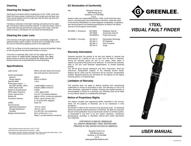
Greenlee
Greenlee 170XL user manual
Eaton
Eaton Sure-Lites 2C installation instructions
System Sensor
System Sensor SpectrAlert CH24MC Series Installation and maintenance instructions
Grasslin
Grasslin talis PF 360-8-2 Operating manual set
Velleman
Velleman PIR700 user manual
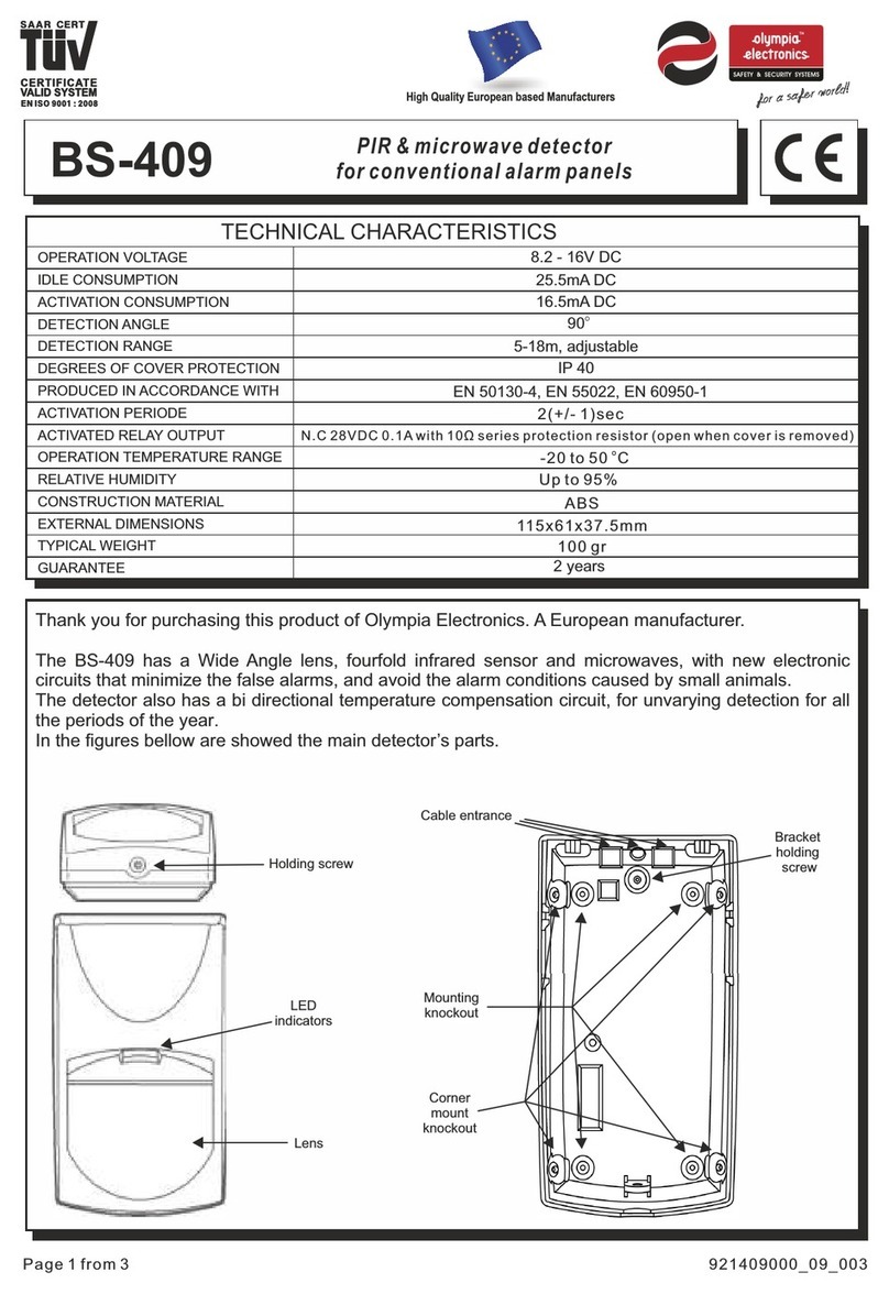
olympia electronics
olympia electronics BS-409 quick start guide
BEA
BEA IXIO-DT3 user guide
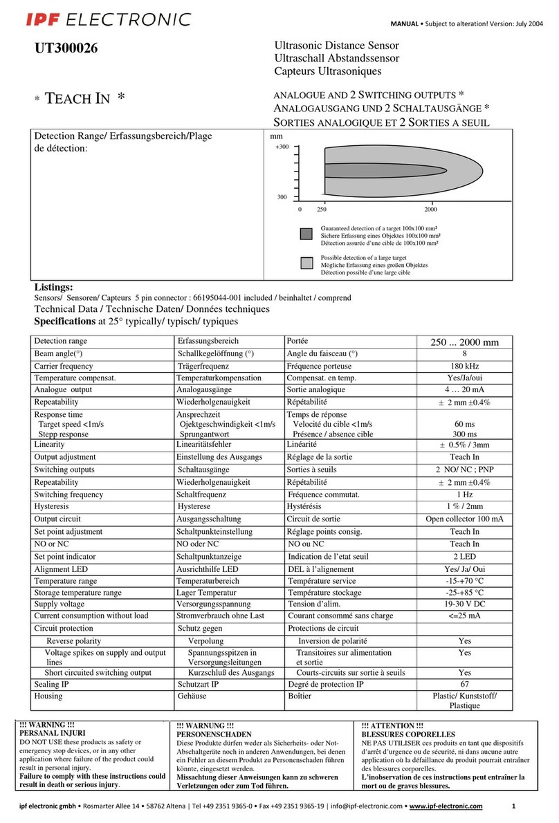
ipf electronic
ipf electronic UT300026 manual
Tecnoalarm
Tecnoalarm INFROTEK MASK quick guide
Danieli Automation
Danieli Automation ID2202 Installation, use and maintenance manual
AMC
AMC SMILE 19 installation instructions


