New Cosmos Electric KS-7R User manual

Carbon Dioxide Detector
KS-7R
Instruction Manual
Keep this manual for easy reference.
Carefully read this manual prior to use.
This manual describes the standard model. If your unit has end-user-specific
options, this manual will be superseded by your delivery specifications.
Instruction Manual No.
GAE-139-01
June 2019

Table of Contents
1. Introduction................................................................................................................................1
2. General Precautions..................................................................................................................2
3. Package Contents.....................................................................................................................3
4. Unit Dimensions and Components............................................................................................4
4-1. Outer Appearance..............................................................................................................4
4-2. Inner Components .............................................................................................................5
5. Installation .................................................................................................................................6
6. Wiring ........................................................................................................................................9
6-1. Pin Terminal/Insulated Sleeve Installation.......................................................................10
6-2. Wire Connection/Disconnection to/from Terminal Block..................................................11
6-2-1. Power Terminal Block ...............................................................................................11
6-2-2. External Output Terminal Block.................................................................................11
6-3. Cable Tie Installation .......................................................................................................11
7. Operation.................................................................................................................................12
7-1. Precautions before Use...................................................................................................12
7-2. Operating Procedure .......................................................................................................12
7-3. LCD Operation.................................................................................................................14
7-3-1. LCD...........................................................................................................................14
7-3-2. Normal Operation Status...........................................................................................14
7-3-3. Full Scale and Alarm Set Values Display..................................................................15
7-3-4. Peak Value Display and Reset..................................................................................15
7-3-5. Operation during Gas Alarm .....................................................................................15
7-4. User Mode .......................................................................................................................16
7-4-1. User Mode Operation................................................................................................16
7-4-2. Switching Maintenance Mode On/Off [Mode 1] ........................................................17
7-4-3. Zero Adjustment [Mode 2].........................................................................................18
7-4-4. Air Adjustment [Mode 3]............................................................................................18
7-4-5. Alarm Test [Mode 4] ..................................................................................................19
7-4-6. Alarm Event History [Mode 5] ...................................................................................20
7-4-7. Clock Setting [Mode 6]..............................................................................................21
7-5. Maker Mode.....................................................................................................................22
7-5-1. Maker Mode Activation..............................................................................................22
7-5-2. Alarm Set Value Change...........................................................................................23
8. Maintenance............................................................................................................................24
8-1. Inspection Contents and Frequency................................................................................24
8-2. Clock Battery Replacement.............................................................................................26
9. Troubleshooting.......................................................................................................................28
10. Specifications.........................................................................................................................30
11. Warranty ................................................................................................................................31
12. Expected Sensor Life ............................................................................................................31
13. Detection Principle ................................................................................................................32
14. Glossary ................................................................................................................................33
15. Proper Product Disposal at End of Life.................................................................................34
- 1 -
1. Introduction
Thank you for purchasing the New Cosmos KS-7R carbon dioxide detector.
To ensure safe and reliable operation, please read this instruction manual prior to use.
This unit detects carbon dioxide and is intended for use in a non-hazardous indoor area, e.g. office,
laboratory, or clean room, for the early detection of a gas leak.
The unit will relay the gas concentration value as an analog signal (4-20mADC) to external
equipment while simultaneously displaying the gas concentration value on its display.
This unit monitors carbon dioxide levels, and when they reach a preset level, the unit will produce
audio-visual alarms and activate relay contacts.
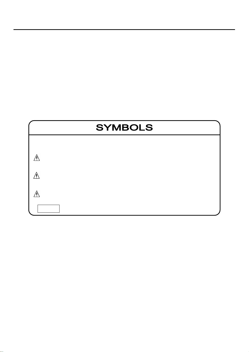
This manual uses Danger, Warning, Caution and Note symbols to draw attention to
procedures, materials, methods, and processes, which require particular attention.
: Indicates an imminently hazardous situation that can result in
death or serious injury.
: Indicates a potentially hazardous situation that may result in death
or serious injury.
: Indicates a hazardous situation that may result in minor injury or
property damage.
: Provides information on product handling.
DANGER
CAUTION
WARNING
NOTE
- 2 -
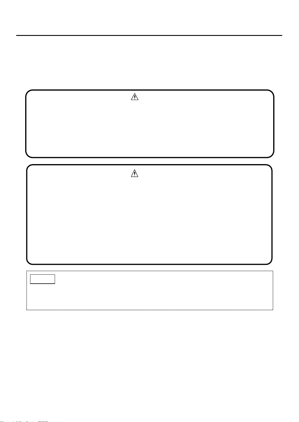
2. General Precautions
Carefully read this manual prior to use.
Follow the precautions below to ensure safe operation.
Only use this product in accordance with applicable laws and regulations.
Only a qualified electrician with knowledge of wiring and installation procedures should perform
wiring and installation.
▪In the event of a gas alarm, follow the safety procedures in accordance with your
company's regulations.
▪This product is not explosion-proof equipment and should not be installed in a
hazardous area.
▪Secure the cover by tightening the two fastening screws. Proper gas detection is not
possible if the cover is not tightly closed.
WARNING
Operation during power outage
In the event of a power outage during operation, the detector will automatically
resume operation once power is restored, provided the main power switch, under
the cover, is in the on (up) position.
NOTE
▪Do not disassemble, modify, or alter the structure of this unit or its electrical circuits.
Doing so may compromise the performance of the product.
▪This product is not drip-proof equipment and should be kept away from splashing
water.
▪Condensation inside the product may cause a device failure. If used continuously in a
high humidity environment, take measures to prevent condensation.
▪The product’s analog output resolution is 1,000 steps. Because of the difference in
resolution or number of displayed gas concentration digits, or connected impedance,
some errors in displayed gas concentration value may be observed.
If the fault threshold needs to be set via analog output, set it to 1.0mA.
CAUTION

- 3 -
3. Package Contents
The following items are included in a standard package. If any items are missing or
damaged, please contact New Cosmos or its authorized representative for replacement.
Item
Qty.
Description
CO2detector (KS-7R)
1
Mounting screw
2
M5x12 with spring washer (wall mounting)
Cable tie
1
To be used to bundle electric cables
Pin terminal
9
To be crimped to cables and inserted into the
terminal block
Insulating sleeve
9
To be installed in a crimped pin terminal to provide
insulation
Instruction manual
1
This manual
Inspection certificate
1
- 4 -
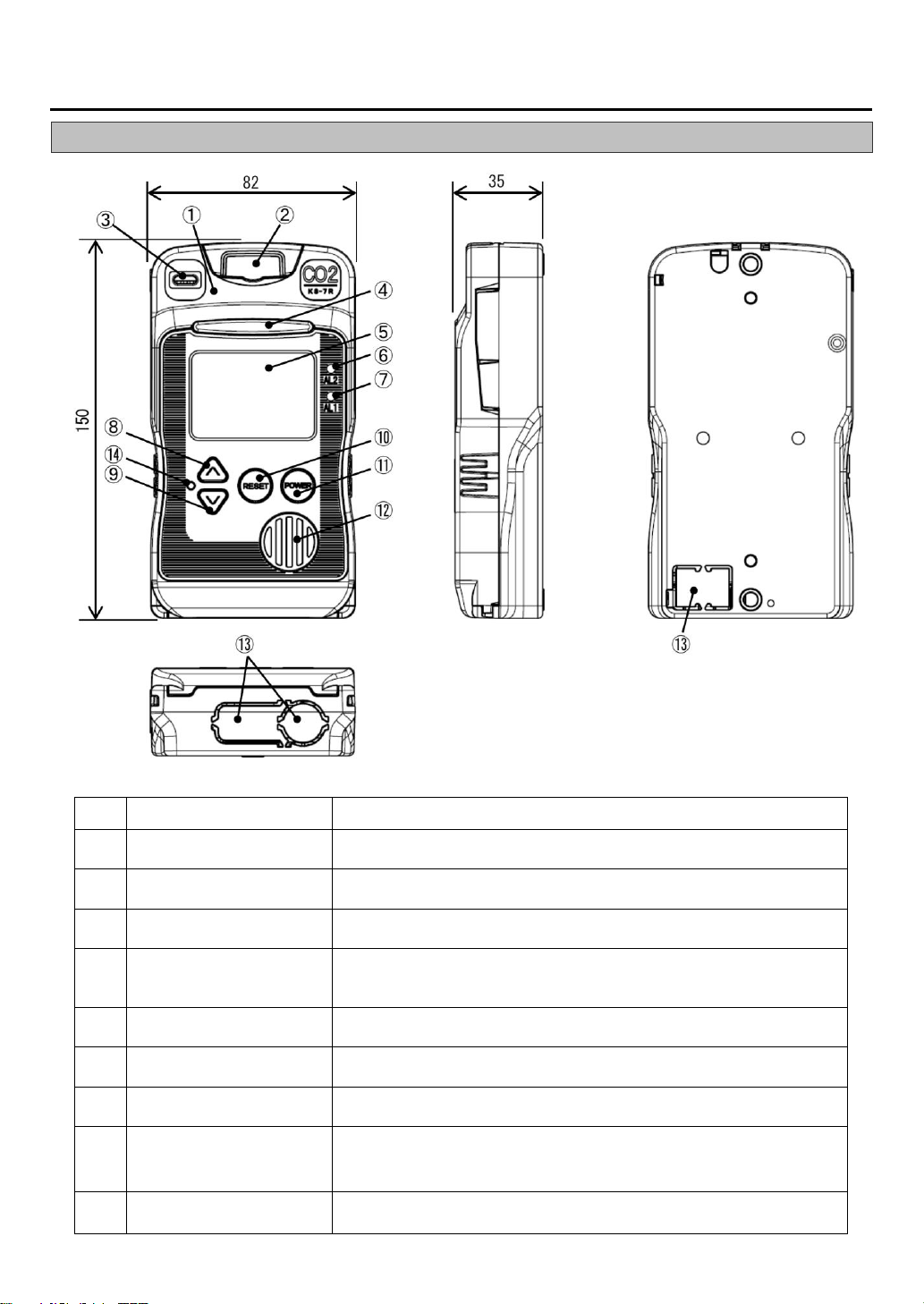
4. Unit Dimensions and Components
4-1. Outer Appearance
Item
Component
Description/Function
1
Cover
Slide up and lift the cover to access to the main power switch and to
wire external cables. This cover is normally closed.
2
Screw cover
Houses one mounting screw, and two fastening screws that attach the
cover to the unit. This cover is normally closed.
3
Gas detection port
Gas inlet to the CO2sensor.
4
Status indicator
During normal operation all three green internal LEDs are lit. In the
event of an 1st/2nd stage alarm, four internal amber/red LEDs light
sequentially.
5
LCD
Displays CO2concentration, parameter values, error codes, and
status icons.
6
AL2 alarm light, red
Flashes red in the event of a 2nd stage alarm. The light will become
solid if reset by pressing the RESET button.
7
AL1 alarm light, amber
Flashes amber in the event of a 1st stage alarm. The light will become
solid if reset by pressing the RESET button.
8
▲ (Up) button
During normal operation, press to display the highest peak value of
gas concentration after powering-up on the LCD.
Used for making settings in combination with other buttons.
9
▼ (Down) button
Used for making settings in combination with other buttons.
Dimensions are in mm.

- 5 -
Item
Component
Description/Function
10
RESET button
During normal operation, press to display the full scale and alarm set
values. Used for muting an on-going audio alarm.
11
POWER button
Press and hold for three seconds to turn on/off the detector.
12
Speaker opening
Opening for audio.
13
Cable entry (3 places)
Make a cutout (cable entry) with a nipper to connect external cables to
the terminals.
14
Maintenance button
Recessed button used for making settings.
4-2. Inner Components
Item
Component
Description/Function
1
Cover
Slide up and lift the cover to access to the main power switch and
to wire external cables. This cover is normally closed.
2
Screw cover
Houses one mounting screw, and two fastening screws that attach
the cover to the unit. This cover is normally closed.
3
Fastening screw (2 places)
Located under the screw cover.
Screws that attach the screw cover to the unit.
4
Terminal block
Connect to external wiring.
5
Main power switch
Turns on/off the main power.

- 6 -
5. Installation
▪Leave a distance of more than 30mm from each side of the detector for
removal purpose.
▪Leave a distance of more than 50mm from the top of the detector to allow the
cover to slide open.
▪Leave enough space for cable wiring below the detector.
NOTE
▪Avoid strong mechanical shock, impact or vibration to the detector by dropping or
bumping. Failure to do so may impair the performance of the detector.
▪Do not install the detector in the following conditions.
- Outdoors
- Exposure to water spray
- Outside the following operating temperature/humidity
-10 to +50 °C (no rapid temperature change)
0 to 85% RH (no condensation)
- Presence of corrosive gas
- Exposure to impact or vibration
- Presence of high frequencies or a magnetic field
- Exposure to electrical noise
- Exposure to dust
- Exposure to high winds (higher than 6 m/s or 13.4 mph)
▪Install the detector in a location that ensures easy access for maintenance.
▪Install the detector vertically with the sensor on top. Proper gas detection is not possible
if installed inverted, at an angle, or horizontally.
▪CO2is heavier than air, so the recommended sensor height is 150 cm (head height)
unless otherwise required by applicable laws or regulations. Install the unit with its gas
detection port free from obstructions.
▪Secure the cover by tightening the two fastening screws. Proper gas detection is not
possible if the cover is not tightly closed.
▪Do not use or store the detector where alcohols, acetone, or volatile oil is present. That
may compromise the product’s detection performance.
▪Do not use or store the detector where chlorine or corrosive gas is present. That may
compromise the product’s detection performance.
▪Exposure to alkali metals especially salt spray) or other inorganic elements may
contaminate the sensor and compromise the detection performance.
▪Accurate measurement is not possible, if installed beyond standard sea-level
atmospheric pressure range (e.g. at high-altitude).
▪
CAUTION
▪This product is not explosion-proof equipment and should not be installed in a hazardous
area.
▪Do not use the product at an area where the CO2concentration is less than 360 ppm.
WARNING

- 7 -
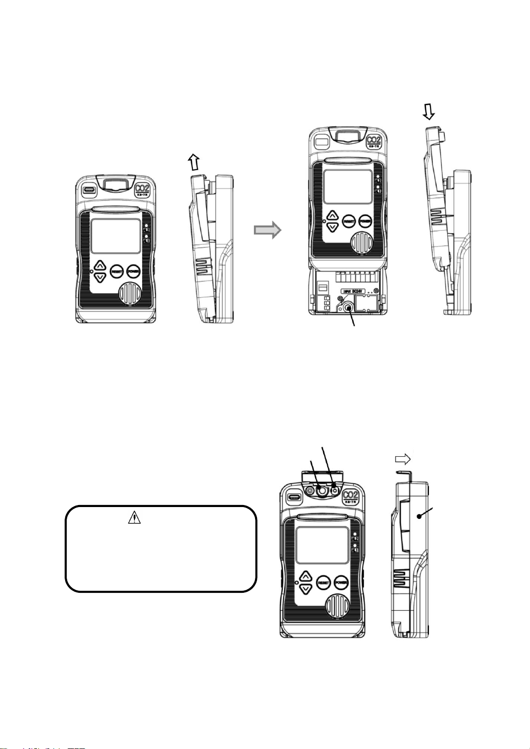
Wall-mount the detector using two M5 mounting screws (pitch: 134) according to the following
procedure.
1. Open the screw cover.
2. Loosely install the mounting screw (top).
3. Loosen the two fastening screws.
4. Slightly pull the cover forward.
Dimensions are in mm.
2. Loosely install
mounting screw (top)
3. Loosen two
fastening screws
Cover
4. Pull cover forward
Screw cover
1. Open screw cover
Clearance for cover
to slide
Cable entry
Mounting hole
Sensor
- 8 -
5. Slide the cover up (cover is open).
6. Firmly tighten the mounting screw (bottom) to secure the detector to the wall.
7. Slide the cover down (cover is closed).
8. While pressing the cover down toward the case,
9. Tighten the mounting screw (top).
10. Secure the screw cover to the case with the two fastening screws.
11. Close the screw cover.
CAUTION
Secure the cover by tightening the
two fastening screws. Proper gas
detection is not possible if the cover
is not tightly closed.
5. Slide cover up
6. Tighten mounting screw
(bottom)
7. Slide cover down
10. Tighten two fastening screws
Case
9. Tighten mounting screw
8. Press down
cover
- 9 -
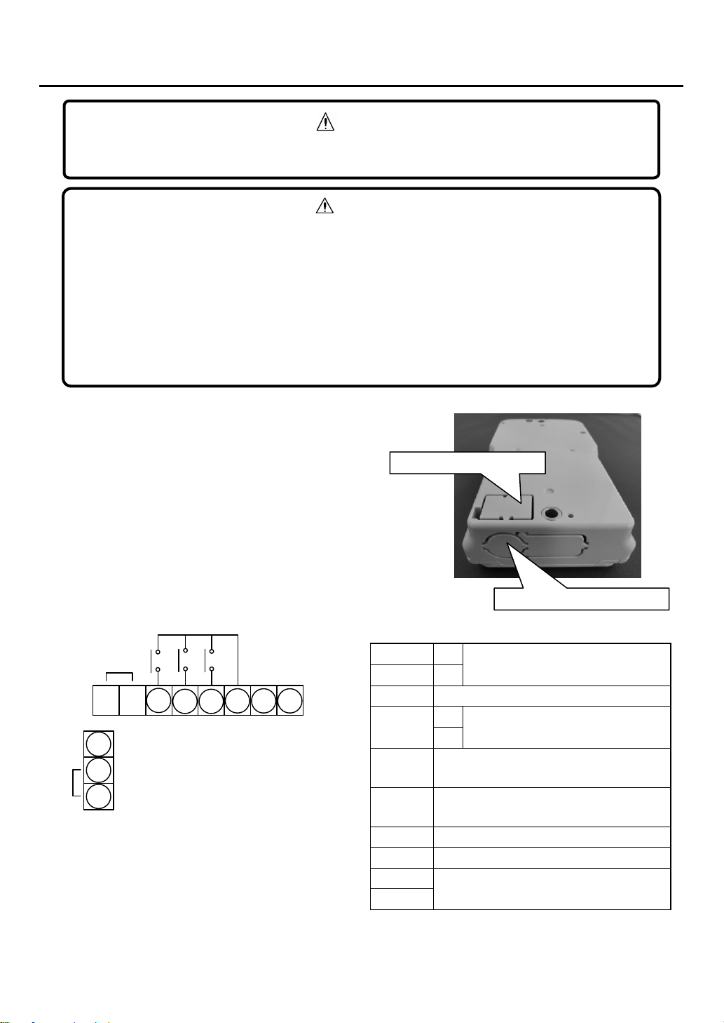
6. Wiring
The knockout holes for cable entry are provided
on the back and bottom of the unit, and can be
removed using a nipper.
Use a shielded cable (with 0.5 to 1.25mm2wires)
up to 500m in length with an outside diameter of
10.5mm or less.
NO: Normally Open
NC: Normally Closed
P
+
Power supply, 24 VDC
N
-
E
Earth terminal for grounding the detector
Signal
+
Analog output, 4-20mA DC
-
ZA1/ ZB1
1st stage alarm relay contact
(Dry NO or NC)
ZA2/ZB2
2nd stage alarm relay contact
(Dry NO or NC)
TA/TB
Faultalarmrelaycontact (Dry NO or NC)
COM
Common
D
Not used
C
NO contacts
-
+
R
S
C
D
COM
Signal
E
N
P
+-
ZA2
ZA1
TA
▪Remove any power source during wiring work to prevent electric shocks.
▪After wiring is completed, close the detector’s cover to prevent electric shocks.
WARNING
▪New Cosmos is not responsible for the cost or any damage resulting from controlling
external equipment (e.g. interlock) by using the detector’s outputs (e.g. analog output,
alarm relay contact output).
▪Connect wires to their corresponding terminals by referring to the marking on the
terminal block.
▪Keep the connection cable away from the electrical power line.
▪When using with external devices, isolate the product’s 4-20mA analog output from
power lines of external devices in order to prevent inflow current and noise.
CAUTION
Knockout hole on the bottom
Knockout hole on the back
- 10 -
6-1. Pin Terminal/Insulated Sleeve Installation
Recommended parts/tools
Part
Model (Manufacturer)
Remarks
Electric cable
Shielded cable (with 0.5-1.25mm2 wires)
Outer diameter: 10.5mm or less
Pin terminal
TC1.25-16 (Nichifu)
(Included in package)
Used for 0.25- 1.65mm2twisted wire
Insulating sleeve
VC1.25 (Nichifu)
(Included in package)
Crimping tool
NH1 (Nichifu)
1.25
Terminal block (reference)
Part
Model (Manufacturer)
Remarks
Power terminal block
ML-1400-S1L-3P
(Sato Parts)
Diameter: 0.65-1.6mm
External output terminal block
FFKDSA1/H1-5, 08-8
(Phoenix Contact)
Diameter: 0.2-1.5mm
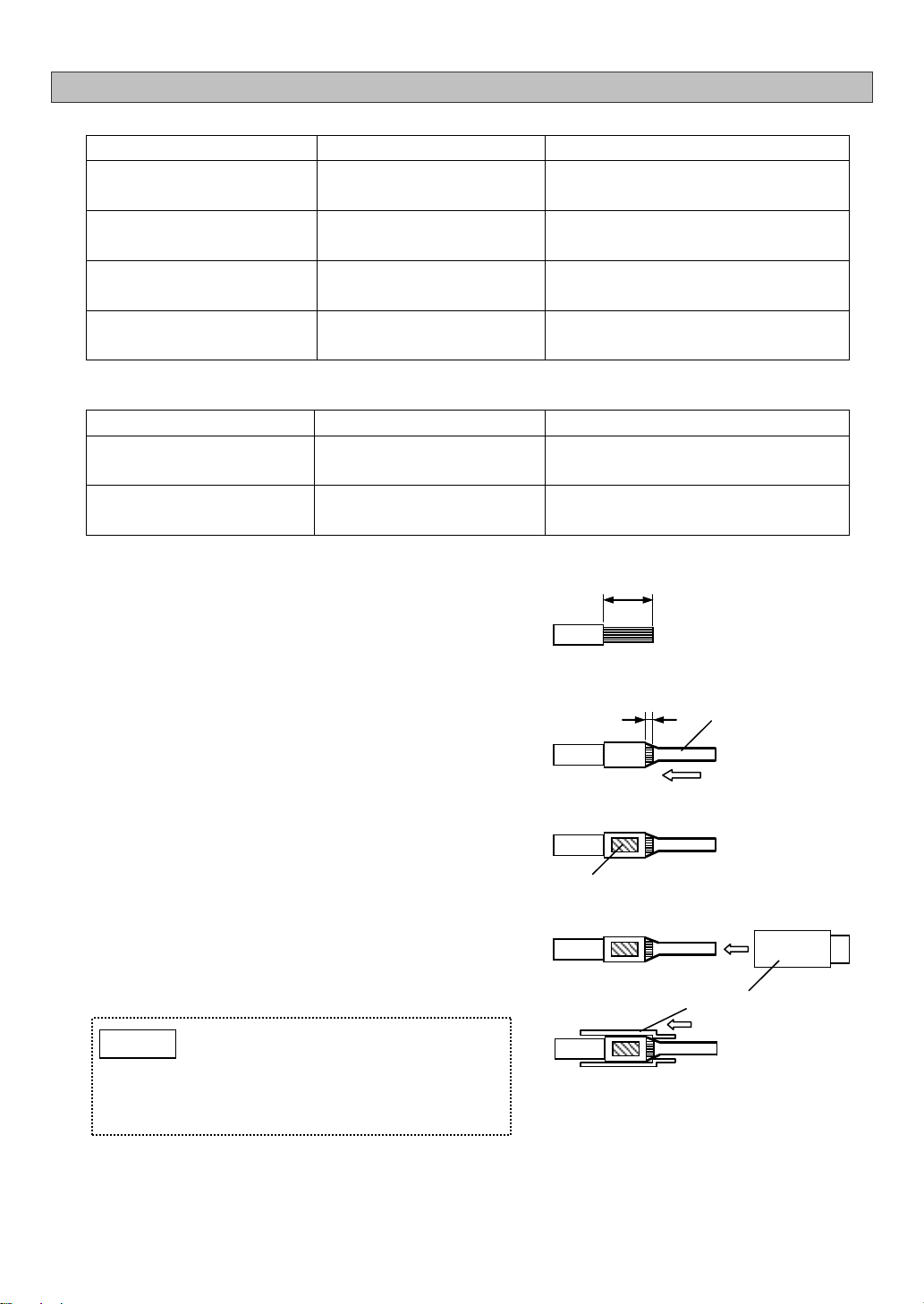
1) Wire stripping
Strip the wire.
Recommended stripped wire length: 5.5mm
2) Pin terminal installation
Insert the stripped wire into a pin terminal until
1mm of stripped wire can be seen from the end
of the pin terminal’s barrel.
3) Terminal crimping
Crimp the center of the barrel.
4) Insulating sleeve installation
Attach an Insulating sleeve to the crimped pin
terminal.
5.5
1
Pin Terminal
Barrel
Insulating sleeve
Completely insert
Completely insert the pin terminal into
the insulating sleeve. Not doing so may
cause an insufficient pin length when
wired to the terminal block, which may
result in a poor connection.
NOTE

- 11 -
6-2. Wire Connection/Disconnection to/from Terminal Block
6-2-1. Power Terminal Block
6-2-2. External Output Terminal Block
6-3. Cable Tie Installation
Use a cable tie for bundling the in-coming cables through
the cable entry and secure them to the unit’s wall.
The unit has a cable tie holder inside its case near the
bottom.
Pre-install a cable tie by feeding it thru the tie holder and
make a loop. To easily bundle the wiring of in-coming
cables to the terminal block, feed these cables thru this
loop and secure to the case wall.
Cable tie
Cable entry
Insert each pin terminal to its
corresponding slot on the terminal block.
(Connection)
(Disconnection)
While pressing the release button with a
precision screwdriver (recommended tip
thickness: 2.6 mm), lift the pin terminal.
(Disconnection)
(Connection)
Insert each pin terminal to its
corresponding slot on the terminal block.
While pressing the release button with a
precision screwdriver (recommended tip
thickness: 3.0 mm), lift the pin terminal.

- 12 -
7. Operation
7-1. Precautions before Use
7-2. Operating Procedure
1) Follow steps 1, 3, 4, and 5 of 5. “Installation”to
slide up and open the cover. (The cover is not
fully opened.)
1. Open the screw cover.
3. Loosen the two fastening screws.
4. Slightly pull the cover forward.
5. Slide the cover up (cover is open).
2) Set the main power switch to the on (up)
position.
3) Follow steps 7, 8, and 10 of 5. “Installation”to
close the cover and tighten the screws.
7. Slide the cover down (cover is closed).
8. While pressing the cover toward the case,
10. secure the screw cover to the case with the
two fastening screws.
CAUTION
Secure the cover by tightening the
two fastening screws. Proper gas
detection is not possible if the cover
is not tightly closed.
Status indicator
LCD
POWER button
▪Before turning on the unit, check that all wiring is correct. Refer to 6. “Wiring”or delivery
specifications if provided.
▪Ensure there is no target or interfering gas in the air before use.
▪Before the sensor output is stable, the relay contacts may possibly activate after the
warm-up completes. If the relay contact outputs are used to interlock external devices,
release the interlocks to prevent possible activation, if necessary.
▪During the warm-up, the analog signal output is fixed at 4mA and the external relay
contacts are disabled.
CAUTION
Screw cover
Cover
Partly
open
Main power
switch
- 13 -
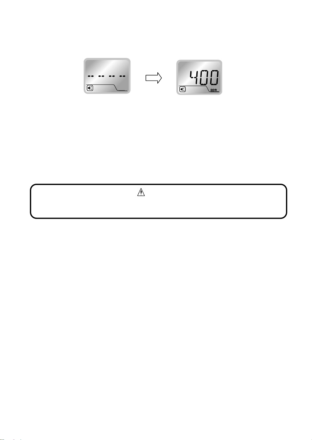
4) Press and hold the POWER button for three seconds to turn on the detector. (two beeps) The three
green LEDs inside the status indicator start flashing and “- - - -”is displayed on the LCD. The
warm-up cycle lasts two minutes. During the warm-up cycle, the analog output is fixed at 4 mA,
gas and fault alarms are deactivated, and the detector cannot enter to User mode.
5) When the warm-up cycle is completed, the three green flashing LEDs inside the status indicator
become solid, the gas concentration is displayed on the LCD, and normal operation starts.
6) Perform an alarm test. (Refer to 7-4-5. “Alarm Test”)
Confirm that an alarm activates.
7) To turn off the detector, press and hold the POWER button for three seconds to stop its operation,
then set the main power switch to the off (down) position.
Warm-up operation
Normal operation
CAUTION
If the gas detector has not been powered for a long period of time (i.e. between shipment
and initial energization), it may take longer for the sensor to stabilize.

- 14 -
7-3. LCD Operation
7-3-1. LCD
Item
Icon/Display
Description/Function
1
Audio alarm icon
Lit during active audio alarm.
2
AL1 icon
1st stage alarm notification.
3
AL2 icon
2nd stage alarm notification.
4
Concentration value and information
CO2concentration value, parameter values, error
codes, etc.
5
Unit of measurement
A unit of gas concentration.
6
Clock battery level indicator
Lit when the clock battery level is low.
7
Alarm event history icon
Lit when an alarm event is being accessed.
8
Maintenance mode icon
Lit when Maintenance mode is active.
7-3-2. Normal Operation Status
During normal operation the green status indicator is fully lit,
the gas concentration value is displayed on the LCD, and
the AL1 and AL2 alarm lights are off.
Buttons and switch
POWER button
RESET button
▲(UP) button
▼(DOWN) button
Maintenance button
CAUTION
▪The LCD indication is fixed at “360 ppm”, even if the actual gas concentration is less.
▪The audio alarm icon is not displayed when your detector is a silent alarm option
(specified at time of order).
1
2
3
4
5
6
7
8

- 15 -
7-3-3. Full Scale and Alarm Set Values Display
▪Press the RESET button (one beep) to display the “full scale concentration”, “1st stage alarm set
value”, and “2nd stage alarm set value”in sequence.
7-3-4. Peak Value Display and Reset
▪Press the ▲button. (one beep) The “peak value after powering-up”and “PEAK”will be displayed
alternately.
▪To return to the normal gas concentration display, press the RESET button. (one beep)
The display will show the full scale value and alarm set values, then return to the normal gas
concentration display.
▪To reset the peak value, press the ▲and ▼ buttons at the same time. (two beeps)
The peak value is reset then the display returns to the normal gas concentration display.
7-3-5. Operation during Gas Alarm
▪When the CO2concentration reaches the alarm set value, the alarm light flashes, the status
indicator sequentially-flashes and the audio alarm sounds.
▪There are two options to clear a gas alarm, manual-resetting and self-resetting. By default, the
detector is set to self-resetting mode. Please specify the alarm clearance option at the time of
order.
▪The alarm hysteresis range is 200 ppm. The alarm will not be cleared until the gas concentration
exceeds the alarm set value by more than the hysteresis value. E.g. when the alarm set value is
2000 ppm and an alarm is activated, the alarm will not be cleared until the concentration reaches
1800 ppm or lower.
E.g. Peak value is 1000 ppm.
Alarm relay contact reset: If the RESET button is pressed while the
concentration is below “alarm set value –hysteresis”, the alarm relay contact will
return to its normal position and the alarm light will turn off.
NOTE
Audio alarm mute: If the RESET button is pressed during a gas alarm, the audio
alarm will be muted and the flashing alarm light(s) will become solid. If the
RESET button is pressed and held, the alarm will not be muted.
NOTE

- 16 -
7-4. User Mode
7-4-1. User Mode Operation
▪To enter User mode, press the maintenance button while
the unit is on. After one beep, “1”and its abbreviated
mode name “MT”will be alternately displayed.
▪To select the mode options, use the ▲and ▼buttons.
▪To confirm your selection, press the maintenance button. To return to the previous step, press
the RESET button.
▪To execute the selected mode, press and hold the maintenance button for three seconds.
▪To return to normal operation mode, press and hold the RESET button for five seconds.
Mode
Mode name
Abbreviated mode name
1
Switching Maintenance mode on/off
MT
2
Zero adjustment
0 ppm
3
Air adjustment
400 ppm
(target concentration level)
4
Alarm test
AL T
5
Alarm event history
AL H
6
Clock setting
DATE
< 1st stage alarm >
▪AL1 alarm light (amber) flashes and the status indicator sequentially-flashes amber.
▪Audio alarm beep: Fast, high and low beep tones.
▪COM-ZA1 alarm relay contact closes. / COM-ZB1 alarm relay contact opens.
< 2nd stage alarm >
▪AL2 and A1 alarm lights (red and amber) flash and the status indicator sequentially-flashes
red.
▪Audio alarm beep pattern: Very fast high and low beep tones.
▪COM-ZA2 alarm relay contact closes and COM-ZA1 alarm relay contact remains closed. /
COM-ZB2 alarm relay contact opens and COM-ZB1 alarm relay contact remains open.
▪During User mode, gas detection, alarm operation, analog output, and contact
output activation are active as during normal operation mode. However, audio
alarm mute and alarm clearance are not active and cannot be used.
▪Return to normal operation mode after using User mode.
NOTE
Use a rounded pin (e.g. precision screwdriver) for pressing the Maintenance
button.
NOTE

- 17 -
7-4-2. Switching Maintenance Mode On/Off [Mode 1]
1) Enter User mode. Press the ▲/▼button to
select “1”. (each press of the button is followed by
one beep) “MT”and “1”(mode number) will be
alternately displayed.
2) Press the maintenance button. (one beep)
“OFF”will flash.
3) Press the ▲button. (one beep)
“ON”will flash.
4) Press and hold the maintenance button for three
seconds (beep pattern: short–long–short–short) to
confirm the selection.
The maintenance icon is displayed, and “1”and
“MT”will be alternately displayed, indicating that
the unit is in Maintenance mode.
5) To end Maintenance mode, take the steps 1) to 4)
above to switch Maintenance mode from “ON”to
"OFF". Confirm the maintenance icon has turned
off.
During Maintenance mode, the gas alarm relay contacts and gas alarm audio are
disabled. Turn off Maintenance mode during normal operation.
WARNING
Maintenance icon
If the unit is returned to normal operation mode
while in Maintenance mode, the “concentration
value”and “- - - -”will be alternately displayed
and the maintenance icon will remain displayed.
NOTE

- 18 -
7-4-3. Zero Adjustment [Mode 2]
Enter User mode. Press the ▲/▼button to select “2”.
(each press of the button is followed by one beep)
“0 ppm”and “2”will be alternately displayed.
7-4-4. Air Adjustment [Mode 3]
Enter User mode. Press the ▲/▼button to select “3”.
(each press of the button is followed by one beep)
“*** ppm”(target concentration level) and “3”will be
alternately displayed.
(E.g. Target concentration level is 400 ppm)
▪Do not perform a zero adjustment. Accurate detection is not possible without proper
adjustment.
▪To adjust the sensor, a zero or air adjustment is necessary. Air adjustment is
recommended.
▪Sensor adjustment (air/zero adjustment) should only be performed by qualified
technician. For adjustment, contact your New Cosmos representative (fees apply).
CAUTION
▪Do not perform an air adjustment. Accurate detection is not possible without proper
adjustment.
▪To adjust the sensor, a zero or air adjustment is necessary. Air adjustment is
recommended.
▪Sensor adjustment (air/zero adjustment) should only be performed by qualified
technician. For adjustment, contact your New Cosmos representative (fees apply).
▪400 ppm CO2gas is used for air adjustment.
CAUTION
Table of contents
Other New Cosmos Electric Security Sensor manuals


Popular Security Sensor manuals by other brands

Techly
Techly I-LIGHT-SNR11TY quick start guide

LinMot
LinMot DM01-48-FS25 installation guide

Lehmann electronic
Lehmann electronic MEDISWITCH VarioFon instruction manual

Maple Armor
Maple Armor FW562-A instruction manual

System Sensor
System Sensor 8100A FAAST Installation and maintenance instructions

Pyronix
Pyronix XD10TTAM manual


Tyco
Tyco WS4933 Series Installation and operating instructions

iNels
iNels RFSF-1B manual

Malta Dynamics
Malta Dynamics C7000 instruction manual

Merritt Manufacturing
Merritt Manufacturing Churchill installation instructions

Nice
Nice HSDIM23 Instructions and warnings for installation and use

ARTELLI
ARTELLI MARS Instructions for use