North FGASE4 Owner's manual

Technical instruction
Manual for use and maintenance
GAS COOKER
MODELS
FGASE4 • EGASE4 • GASE2 • GASE2A • GASE2B • FGASE6 • EGASE6 • GASE21 •
GASE22 • GASE23 • GASE24 • GASE26
These appliances comply with requirements of E.E.C 90/396
SOTIRIOS D. PRODANAS & CO
PROFESSIONAL ELECTRIC & GAS MACHINES FOR RESTAURANT – PATISSERIES – SNACK BAR
OFFICE – FACTORY :National Road Kilkis-Thessaloniki (Entrance Galiko) Tel ++30 23410 41819 Fax ++30 23410 41539
P.O Box 400 70, P.C : 560 00 www.north.gr - e-mail : info@north.gr

1. PART I – INSTALLATION
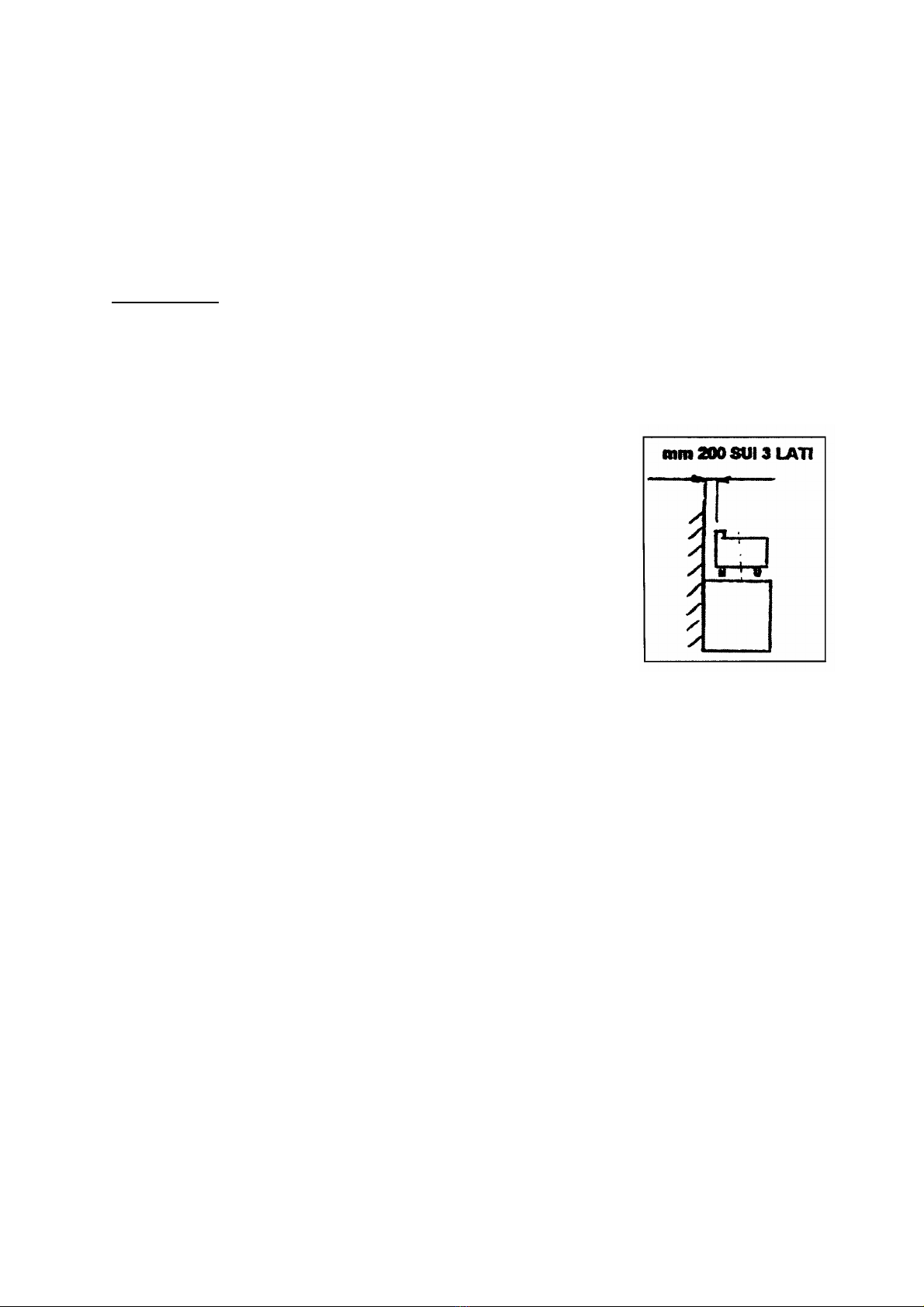
We will present the essential data, technical characteristics and our advice for the
correct installation, use and maintenance of the appliances described. Let us remind
you that the appliances are professional use and that all procedures of installing,
connecting to the distribution network and positioning of the appliance in operation
should be carried out by properly qualified personnel and that all safety measures
applicable in the country of installation should be observed.
The manufacturer cannot be held responsible for any possible damage to
property, human beings or animals that might be caused by misuse of the
appliance or by using the appliance for purposes other than those
recommended for or not foreseen in this manual.
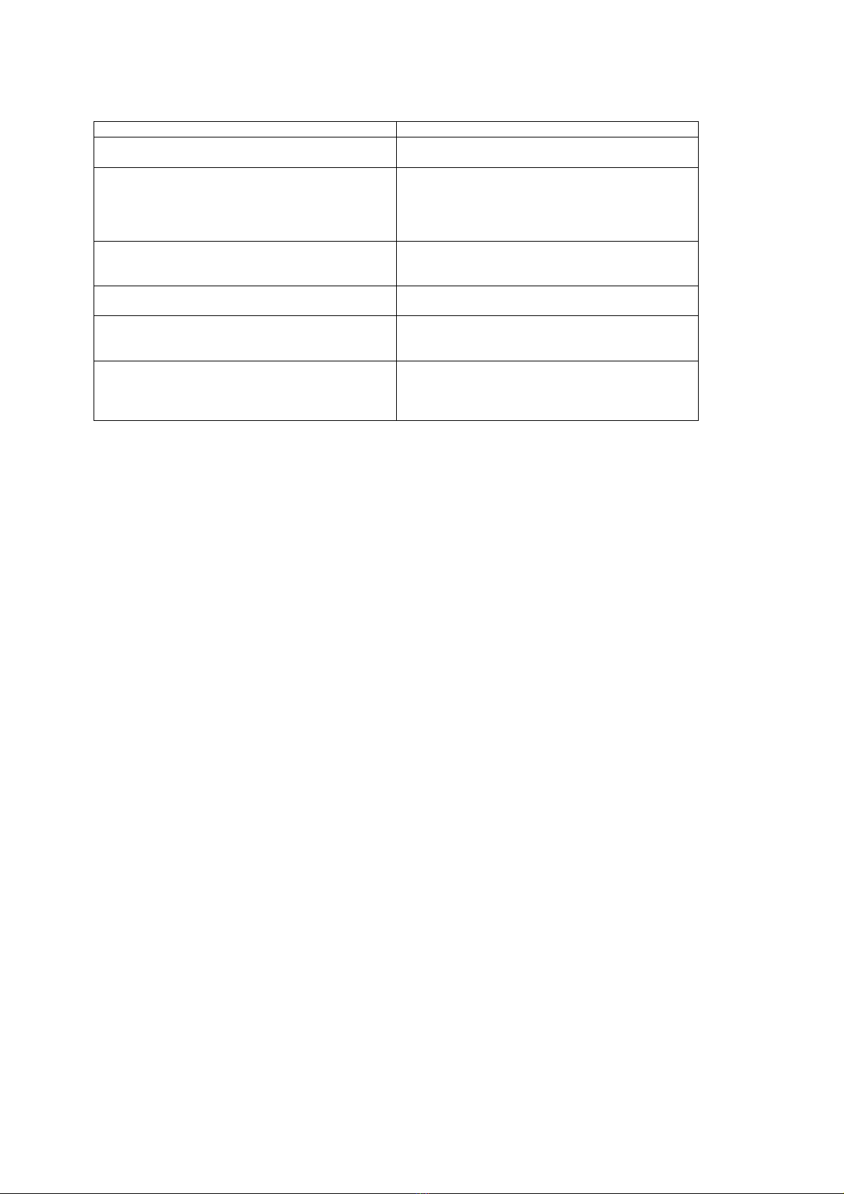
FIGURE 1: Technical Characteristics
Consumption Calories
Model Dimensions
(cm) Oven
Dimensions Type Frame Burner kW G30
Kg/h G20
m³/h G25
m³/h Mj
GASE21 32,5X36,5X16 - A INOX CAST IRON 6 0,43 0,49 0,62 21,6
GASE22 62,5X36,5X16 - A INOX CAST IRON 10,5 0,83 1,11 1,29 37,8
GASE23 93X36,5X16 - A INOX CAST IRON 16,5 1,32 1,60 1,92 59,4
GASE24 62,5X70X16 - A INOX CAST IRON 21 1,62 2,20 2,52 75,6
GASE26 93X70X16 - A INOX CAST IRON 31,5 2,34 3,24 3,82 113,4
GASE2 40.5 X 70 X 43 - A INOX CAST IRON 10.5 0.83 1.11 1.29 37.8
GASE2A 82 X 40.5 X 43 - A INOX CAST IRON 7.5 0.59 0.79 0.92 27
GASE2B 82 X 40.5 X 43 - A INOX CAST IRON 9 0.71 0.95 1.11 32.4
EGAS4 82 X 70 X 43 - A INOX CAST IRON 18 1.42 1.90 2.22 64.8
EGAS6 119 X 70 X 43 - A INOX CAST IRON 27 2.13 2.86 3.32 97.2
FGASE4 82 X 70 X 95 55x52x25 A INOX CAST IRON
& INOX 24.5 1.93 2.59 3.02 88.2
FGASE6 119 X 70 X 95 55x52x25 A INOX CAST IRON
& INOX 33.5 2.64 3.54 4.12 120.6
Unit Big Medium Small Oven
Normal Thermal energy provided KW 6 4.5 3 5
Reduced thermal energy provided KW 2 1 1 1.70
G 30 Main air regulation at 28… 30 mbar Mm APERTA APERTA APERTA APERTA
G 20 Main air regulation at 20 mbar Mm 11 APERTA 8.0 9
G 30 Main air regulation at 50 mbar Mm 16 APERTA 8 11
G 25 Main air regulation at 25 mbar Mm 11 APERTA 8 9
G 25 Main air regulation at 20 mbar Mm 11 APERTA 8 9
G 30 Main burner nozzle at 28… 30 mbar Mm 1.25 1.20 0.85 1.30
G 20 Main burner nozzle at 20 mbar Mm 1.90 1.60 1.30 2.00
G 30 Main burner nozzle at 50 mbar Mm 1.10 0.95 0.75 1.15
G 25 Main burner nozzle at 25 mbar Mm 2.00 1.65 1.40 2.10
G 25 Main burner nozzle at 20 mbar Mm 2.10 1.70 1.45 2.20
G 30 Pilot burner nozzle (28… 30 mbar and
50 mbar) No 20 20 20 20
G 20 Pilot burner nozzle at 20 mbar No Registered Registered Registered Registered
G 25 Pilot burner nozzle at 20 mbar & 25
mbar No Registered Registered Registered Registered
G 30 by-pass valve (28… 30 mbar and 50
mbar) Mm 55 40 40 --
G 20 by-pass valve at 20 mbar Mm Registered Registered Registered Registered
G 25 by-pass valve at 20 mbar & 25 mbar Mm Registered Registered Registered Registered

1.1 Standards and Requirements
We would like to remind you that appliances installed in places open to the public should
meet specific requirements. Among them there are:
• Specific standards for the type of public place.
• Safety standards against fire and cause of panic in public place.
• General standards for the installation of cooking appliances in refreshment
facilities.
• General standards concerning installation using combustible gas and liquid
hydrocarbons.
1.2 Packing
Make sure packing is intact before removing the appliance. Open cardboard carefully to
ensure no metal stapling, adhesive tape or other packing components litter the
environment, as these can prove hazardous.
1.3 Obstacles and Position
• Make sure there is enough space available for the placement of the appliance.
Make sure that the surface it stands on is stable and level.
• Remove the protective tape from the external parts of the appliance, making sure
no glue or plastic is stuck on the surface. If there are residues of glue, remove
them using the right solvent.
• Make sure the appliance is level on the surface available. If necessary, regulate its
height accordingly, by adjusting the legs of the appliance.
1.4 Connection
Before connecting the appliance to the network make sure that:
• The gas available it is the one the appliance is regulated for. If it is not, do not
proceed with connection. Regulate the appliance for the gas available following
instructions under 2.2.
• Burners are manufactured to stand thermal and mechanical stress and are
equipped with fixed nozzles. This is why it is necessary to change the nozzles
every time you change the type of gas.
• Data concerning the regulation of the appliance are to be found on the label of the
right hand wall.
• Connect the appliance to the network using only metal piping, either rigid or
flexible.
• Make sure the pressure used is the pressure the appliance is regulated for. In no
case should pressure exceed 50 mbar.
• Use the right sealing materials for all connections and check them for leaks.
• It is important for walls adjacent to appliance to be protected from the heat. Use
refractory materials or allow at least 200mm between the appliance and any
adjacent walls (see figure below).
• Network connection should be made through a gate valve. This valve should be
closed when the appliance is not in operation.

1.5 Combustion Products
Appliances should be installed in places appropriate for the removal of fumes according
to installation specifications. Our appliances are classified as gas type A.
Such appliances must send fumes into appropriate air extractors connected to safe and
effective pipes that direct them outdoors.
! CAUTION !
Appliances must always be positioned below 200 mm ON THREE SIDES an air
extractor, which directs fumes outdoors.
Appliances with an overall thermal power exceeding 14 Kw must be installed below an
air extractor with a switch and pilot for the gas supply system.
Specifically, the supply circuit electric valve at the top
of the appliance must be switched-off.
Make sure there are set by installation standard UNI-CIG 8723,
point 4.3 ‘’Removal of combustion products’’.
Indicatively, the air extractor must guarantee aspiration power
equivalent to 35 m³ of air per hour for every Kw of thermal
power provided.
Pipes to collect fumes from the appliances and direct them to
a single air-extractor point can be provided at your request.
In this case, too, the appliance must be placed under an
air-extractor.

2. OPERATION
The appliance operates under normal power with the nozzles mentioned above (see
Table of Figure 1). Supply pressure must correspond to the value mentioned in the
relevant data table.
2.1 Pressure Control
In order to measure the supply pressure, you need a liquid manometer with a minimum
sub-division of 0,1 mbar (eg a U-shaped pressure gauge).
Follow this procedure:
• Remove the appliance to regulate the opening to be found behind.
• Unscrew the screw shutting the pressure valve.
• Connect the manometer and measure the pressure.
• Remove manometer, re-screw the screw and make sure there are no leaks.
2.2 Regulation for operation with varius gases
Both the packaging and the appliance carry the regulation data for suitable gases. If
regulation is necessary for another type of gas, you should:
a) make sure which type of gas and pressure correspond to the values mentioned in
the relevant data table.
b) Choose the right nozzle for the specific type of gas and the pressure available in
place, keeping in mind data included on Figure 3 of this manual (keep in mind that
pressure should never exceed 50 mbar) and replace nozzle, if necessary.
2.3 Main burner regulation
• Replace nozzle by unscrewing it and screwing the one appropriate for the type of
gas.
• Regulate main air supply through the regulating ring, adjusting distance A as seen
on the Table of Figure 1.
• In order to regulate the flow of the main air supply, unscrew place ring in desirable
position and screw the screw back on until shut.
• To make sure the regulation of the main air supply is the right one, see that no
flames break away from the burner when it is cold and there is no flame going back
into the nozzle when the burner is hot.

2.3 Regulation of the pilot burner
In order to regulate the nozzle of the pilot burner, it is necessary to remove the base wall
so that you can gain better access to the pilot.
• The nozzle of the pilot burner has a bore regulated for gas G30. In order to adjust it
for the use of G20, unscrew the connection that keeps the nozzle in place.
• Using a small screwdriver unscrew the nozzle anti-clockwise until the flame is
properly regulated.
• Return any parts you may have removed into their previous position.
• No regulation of main air supply is necessary for the pilot burner. In order to
regulate the flame, light the pilot burner and make sure the flame is of a regular
shape and reaches the thermal couple. If flame is not regular, check the regulation
again.
2.4 Operation Control
• Check that the appliance is level on the supporting surface.
• Make sure there is a good clean air inflow.
• Make sure there are no leaks or loss of gas.
• Set the appliance in operation.
• Check flame stability of both the main and the pilot burner.
• Make sure non-combusted gases have an appropriate outlet.
2.5 Interventions, repairs and replacements
(for authorized technicians only)
Even if the appliance is used correctly, some problems may arise for various reasons.
The table that follows mentions some possible problems and some suggestions to put
them right.
! CAUSION !
• Before any intervention for maintenance, repairs or simple cleaning of the
appliance, you must shut the gas supply gate valve at the top of the appliance.
• At the end of any intervention for maintenance or repairs to some parts the
appliance related to gas, check for air-tightness and make sure there are no leaks
or losses.

FIGURE 3 Possible Problems
PROBLEM POSSIBLE EXPLANATION
Gas smell Possible gas loss:
Check external pipes and connections
Smell of non-burned gas
Check that combustion is proper / Check that gas
consumptions is not excessive / Check that hot
fume circuit is not obstructed / Check that air-
extractor and area ventilation are operating
property
The pilot burner does not light Check that the electrode is property placed.
There may be a leak in the gas supply pipe or a
problem with the nozzle
The pilot burner goes out Check that the flame is large enough to heat the
thermal couple
‘’Explosions’’ in the burners Check gas pressure.
Make sure the pilot burner flame is not too far from
the main burner
The main burner does not light
Check there is a leak in the gas supply pipe or any
problem with the nozzle / The burner parts may be
improperly placed / Check the position of the pilot
burner
2.6 Gate valve
• The valve that regulates the gas inflow offers thermal safety, which makes sure
that the gas flow is interrupted if the flame goes out.
2.7 Regulation of minimum burning
• The (by-pass) valve nozzle has 1,20mm bore and has to be fully screwed for gas
G30. In case of regulation for other gases (G20), the by-pass has to be unscrewed
(by turning the screw anti-clockwise until a clear and regular flame appears). In
order to regulate the by-pass, light the burner at the minimum setting, remove the
handle from the valve and regulate the screw marked with an arrow, until a clear
and regular flame appears. The regulation must be fully screwed when changing
from methane to G.P.L. or must be open in the opposite case.
2.8 Interventions and repairs
• If intervention is necessary in the gate valve, all you have to do is to remove the
handle and the front wall.
• In order to replace the gate valve you need to unscrew the connections in the
following order:
First, the connections of the thermal couple and the pilot burner, then the
connection of the gas outlet and, finally, the connection of the gas inflow.
• Replacing other parts, such as the pilot burner, the thermal couple and the ignition
source is simple, once the base wall is removed.

3.PART III – For the user
3.1 Operation – General Precautions
We would like to remind you that these appliances are designed exclusively for
professional use and must be operated by specialized personnel.
In order to set the appliance into operation, observe meticulously everything included
in these pages as well as ordinary safety measures:
• Make sure there is no gas leak.
• Check that the flame is regular by going from maximum to minimum settings.
• Check that the burner lights properly along its full length.
• Check that the pilot burner operates properly.
• Make sure there is a good inflow of clean air.
3.2 Lighting
• When fryer is off, the gate valve handle is vertical and the round indication is at the
top.
• Press the handle slightly and turn it anti-clockwise until you bring it to the flame
indication.
• While you keep the handle pressed, light the appliance using the piezoelectric
ignition device. The flame of the pilot burner will light (the first time you light it, you
must persist because the pipes are full of air and it might take some time before
the burners light).
• Once the pilot burner is lit, keep the handle pressed for a few seconds until thermal
safety couple warms well.
• Turn the handle anti-clockwise until you bring it to the position of the highest flame
and make sure the burner is fully lit.
• The next position is that of the medium flame; you can choose this setting once the
oven has reached the desirable temperature.
3.3 Maintenance
• Before you carry out any maintenance work, you must shut the gas supply gate
valve found at the top of the appliance.
• The user should sign a maintenance contract with technical personnel; this
contract should foresee at least one full check-up annually.
• We specifically recommend regular checking to make sure the pilot burner the
ignition source and the flame regulator are clean.
• The gate valve must be checked at least once a year and, if necessary, the
specific protective oil should be replaced.
• If all instructions of this manual are observed, NORTH appliances will be of perfect
service for a long time.
• The manufacturer cannot be held responsible for any damage caused to property,
human beings or animals due to misuse of the appliances or non-observance of
the instructions included in this manual.
This manual suits for next models
11
Table of contents
Other North Cooker manuals