Northeast Aerodynamics 2M Aquila F3A User manual
Copyright © 2008, Northeast Aerodynamics, Inc. v1.1
2MAquilaF3A
AssemblyManual
Fig1:Completed2MAquilaF3A
(YellowColorSchemeShown)
SPECIFICATIONS
EngineRequirement1.20to1.40cu.In.2C
AXI5330/FAI(orequivalent)
WingSpan70in.
WingArea900sq.in
FuselageLength77in.
WeightRange9.3lbs
WingLoadingrange21.9oz/sq.ft.@9.3lbs
CubicWingLoading8.8
RadioFunctionThrottle,Elevator,Rudder,Aileron
NumberofServos5

- 2 -
Introduction
TheAquilaF3APatternairplanewasbornoutoftheneedforhighqualityARF
airplanescapableofcompletingtheMaster'spatternwitheaseyetbeableto
beflownbynoviceF3ApilotseffectivelyintheSportsmanclass.Bylookingat
theindustrywedecidedtobuildthisairplanearoundtwodifferentpower
plants.
ThefirstpowerplantistheOS1.20AXenginewiththestockmuffler.This
engineismorethancapableofflyingthisairplanethroughthesequences
withoutthecomplexityofapiped‐enginearrangement.Thissimplifiesthe
designandmaintenancesothattheentrylevelF3Apilotcaneasilytransition
fromhisSportairplanetoanF3Acapableairplane.
WantaPipe?ApipetunnelishiddenbeneaththeMonokoteonthebellyof
theAquila.Soifastandardmufflerarrangementisnottoyourliking,oryou
justwantmorepower,youcaneasilyaddyourpipetothisairplane!
ThesecondpowerplantistheAXI5330/FAIelectricmotor.Couplethismotor
witha10SpackofLiPobatteriesandyou'llhaveanelectricF3Aairplane
capableofcompletingtheMaster'spatternschedulewithpowertospare!
TheAquilahasreceivedthebenefitof2yearsdevelopmentanddesignand
wasdesignedfromthegrounduptobeathoroughbredF3Aperformerand
notasportairplanethatlookslikeapatternship.
Ourwhitecolor‐schemewasselectedafterlengthydebatesandisdesignedfor
easeofvisibilityduringallaspectsofflightfromtake‐off,maneuvers,to
landing.WehaverecentlyaddedaYellowcolor‐schemetoourAquilaF3A
ARFs.WecoverourAquilaARFsonlyinhighqualityMonokotefilm.

- 3 -
Builtusingthelatestdesignandmanufacturetechnologies,thekitfeaturesall
built‐upconstructionforeaseofmaintenanceandrepair,shouldyouneedto.
Thedesignwasalsogivenenoughgroundclearancetosupportan18"
propeller.Theairplanealsofeaturesafloatingfirewallarrangementthatlets
youexactlypositionyourmotor(electricorglow)tothecowlandspinner
plate.Oncepositioned,thefloatingfirewallisfixedinplace.
Wantsomethingdifferent?Sendusasketchwithyourowncolorscheme.If
yourschemehasbroadappeal,we'llconsideritforinclusioninourcolor
schemeofferingsandyou'llgetthecreditforthecolorschemedesign.
Thehardwarepackageisfairlycomplete;howeverthehardwareismetric‐size.
You'llneedtoaddyourradiogear,engine,etc.Controlhornsareprovided,as
arethewheels,andothercomponentsincludingafueltank.Asalways,itis
yourresponsibilitytoensurethehardwareyouuseinyourairplaneis
satisfactoryfortheconditionsyouintendtoflyin.Pleasefeelfreeto
substitutehardwareandinstallationpracticesasyourexperiencedictates.
TheconstructionoftheAquilaF3Aismostlybalsa,lite‐ply,andsomefiberglass
(cowl,wheelpants,etc).Thisenablesustobuildtheseaircraftverylightand
verystrong.The2‐piecewingissupportedbyanannealedaluminum25mm
diameterwingtubeandsocket.Thehorizontalstabilizersarealsosupported
byatubeandareremovableforeasytransportation.

- 4 -
Tools,Supplies,andAccessories
TOOLSNEEDEDTOBUILDTHE2MAQUILAF3A
Phillipsandpan‐headscrewdrivers(various
sizes)
CanopyGlue
ElectricorhanddrillandvariousdrillbitsHingeGlue
Needle‐nosedpliersLow‐tackMaskingtape
#11knifeThread‐lockingcompound
SmallMetricsocketsThinandMediumThickCA
8‐32Tap
ACCESSORIESNEEDEDTOCOMPLETETHISKIT
(1)Receiverandon‐boardradiogearper
yourspecifications
(1)12”fuelline
(1)engine(1)muffler
(5)StandardSizedHigh‐PrecisionServos
(DigitalServosarepreferred)
(?)22‐AWGservowiretosupportyour
servoinstallation
6‐32all‐threadrodforruddercontrolhorn4‐40orHeavyDutyPull‐Pullsystemfor
Rudder
(2)8‐32x1.5”socket‐headboltsforaxles(4)8‐32nyloninsertnuts
Pre‐ConstructionAids
Pleaseinspectthekituponarrivalandfamiliarizeyourselfwithallpartsinthe
kitandtheinstructionspriortobeginningconstruction.
Note:Alloftheboltsandnutsshippedwiththiskitaremetricthreadandsize.
Manyofthemountingpackagesofmountinghardwarearegenericforusein
multipleairplanes–notalloftheseitemswillbeusedbytheAquila.

- 5 -
BillofMaterials
o1FuelTankBagincludingafueltank,stopperandhardware.Fueltankismarkedas380mlin
volumebutisactually450mlinvolume.
o2nylonzip‐ties,inawhiteplasticbag,tomountthefueltankintothefuselage.
oTailWheelBagincludingmountinghardware.
o1MainWheelBagincluding2wheelsandmountinghardware.Werecommendreplacingthe
hardwareincludedinthisbagwith(2)8‐32x1.5socketheadboltsand(4)nylon‐insertnuts.
o1EngineMountincludingmountinghardware.Althoughthisenginemountandhardwarecan
beusedwiththekit,werecommendtheHyde‘C’mountfortheOS1.20AXengine.
o1SetAluminumLandingGearwithmountinghardware.NotethereisaLeftandaRightgearleg
andtheboltsare4mmthickand20mmor16mmlongalongwithappropriatelysizedwashers.
o13‐1/8”RedSpinnerwithmountinghardware.Werecommenda3”FAI‐styleTrue‐Turn
spinner.
o22CAHinges
o1PackageofCockpitMountinghardware(with2nylonboltsinsidetoholdthecockpitinplace
throughthefuselagesides).
o1Pull‐PullRudderCableset.Werecommendreplacingthiswitha4‐40heavydutypull‐pullset.
o1Packageofcontrolhorns.Thispackagealsoincludesasetforuseontherudder;however,
theywillnotfittheAquila’srudder.Werecommendusing6‐32all‐threadrodforcontrolhorns.
o1Packageof(2)wheelpants.
o1Packagefloatingfirewalllasercutwood.Assemblyrequired.
o1Wingtube‐‐25mmO.D.x26”length,with0.05”wallthickness
o1Stabtube–12.5mmO.D.
o1PackageElevatorpushrodassembly
o1Fuselagewithcowl,cockpitandcanopy
o2Stabilizer/elevatorhalves(leftandright)
o2Winghalveswithailerons(leftandright)
o1Rudder
o1bagofbolts,screws,plywood:
o(4)SocketheadM4x16mmformountingthelandinggeartothefuselage
o(4)SocketheadM3x20mmformountingthehorizontalstabilizerstothefuse
o(2)8‐32x2”NylonSlottedheadboltsforretainingthecockpittothefuselage
o(4)self‐taping#2x9/16”screwsformountingthecowltothefuselage
o3.5mmplywoodelevatorbearingdoubler
- 6 -
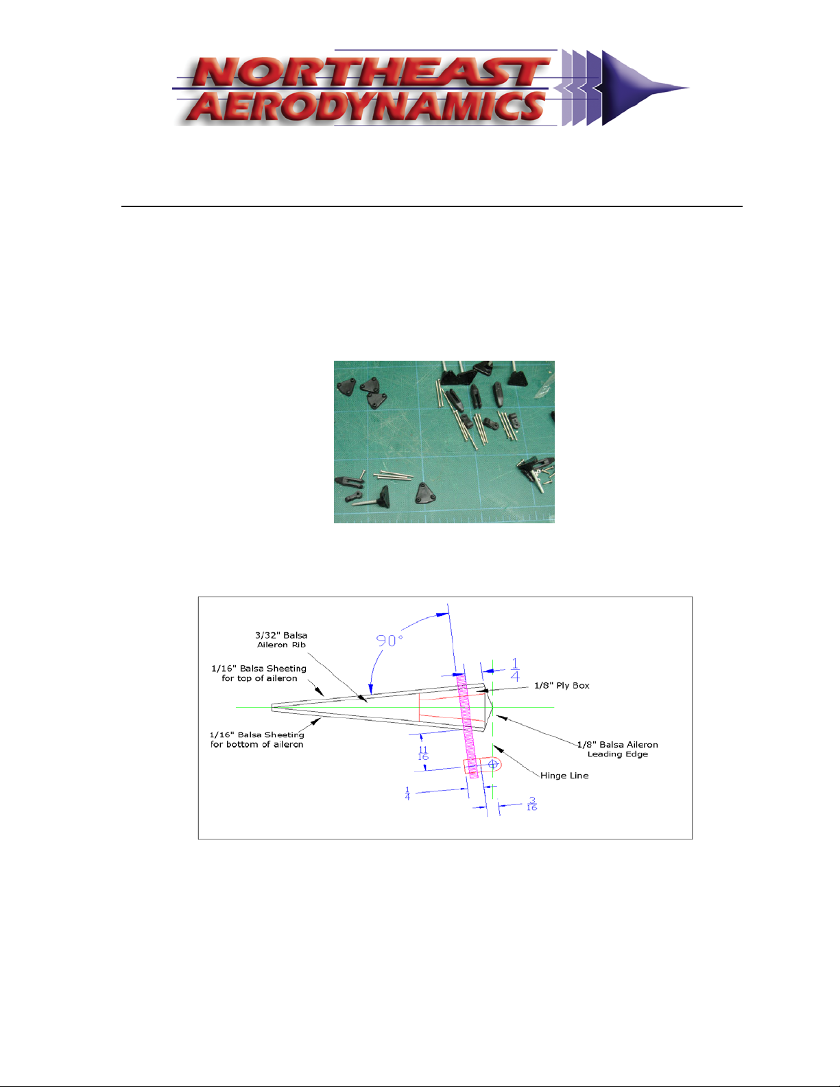
Attachingthecontrolhorns
1. Acompletesetofcontrolhornsareprovidedforyouinthekit.These
controlhorns,withtheexceptionoftherudderpair,canbeusedwith
yourAquilakit.However,werecommendthatyoureplacethe
providedhardwareanduse6‐32all‐threadrodtocreateyourcontrol
horns.
Apicturebelowwillguideyouinaddingthe6‐32controlhornsproperlyto
yourAquilaairplane:

- 7 -
AttachingtheControlSurfaces
1Selectacontrolsurfacetobeginwith,liketherightaileron.
2Removetheaileronfromthewing.
3Examinethepre‐cuthingeslots.Adjusttheseasneededtoensurethe
slotsarecenteredonboththewingandtheaileron.
4Lookingatthehinge,imagingthehingelineonthehinge.Pushapin
throughthecenterofthehingecenteredonthehingeline.Repeatfor
allofthehingesontheaileron.
5Insertthehingesintothecontrolsurfaceuntilthepincontactsthe
aileron.Thepinwillstopthehingefromgoingintotheaileronmore
thanhalf‐way.Dothisforalloftheaileronhinges.
6Aligntheailerontothewingandgentlyinsertallofthehingesintothe
wingwhilekeepingthehingehalf‐wayintheaileron.
7Oncetheaileronisproperlyseated,use3‐4ofdropsofthinCAfrom
thetopofeachhinge.
8FlipthewingoverandaddacoupleofdropsofthinCAtothebottom
ofthehingeandallowtheCAtocurecompletely.
9Removethepinsandflextheaileronuntilitmovesfreely.Checkfor
properandfreemovementofthecontrolsurface.Adjustasneeded.
10 RepeatSteps1through8foralloftheremainingcontrolsurfacestobe
hinged.
11 Setasideandallowtheseassembliestodrycompletely.
12 Itisagoodideatosealthehingelinewithsomeextracovering
materialorpackingtape(notprovided)fromtheundersideofthe
hingeline.

- 8 -
InstallingtheRudderServo
1. Installyourrudderservointotheprovidedmountinsidethefuselage
underthecockpit.
2. Locatethepull‐pullwireexitholespre‐cutintothefuselagesidesand
openupthecoveringhereasneededtorunyourpull‐pullcables
cleanlybetweenyourruddercontrolarmsandtheservocontrolarms.
3. Installthepull‐pullwirepertheinstructionsthatcamewiththepull‐
pullwirekityouselectedusingtheguidesbuiltintothefuselagesides.
Use4‐40gaugehardware.
4. Tensionthepull‐pullwirestoyourpreferences.
MountingtheHorizontalStabilizers
1. AttachyourselectedElevatorControlhornstotheelevatorhalves.
2. Usingthestabtubeprovidedattacheachstabilizerhalfwiththescrew
andwasherprovidedintothe3mm“T”‐nutsburiedinthefuselage.
Useadropofmedium‐holdthread‐lockingcompound(youdowantto
beabletoremovetheseboltssomeday)tosecurethestabboltsin
place.
3. Sincethesizeofthestabtubesleevevariesslightly,yourstabtubemay
havealightlyloosefitoraslightlytightfitforthefuselagesectionof
thesleeve.Werecommendthatyousandthetubeslightlyinthe
centersectiontoallowatighttubetofiteasierandthatyoubuildup
thecenterofthestabtubeifithasaslightlyloosefit.

- 9 -
MountingtheElevatorServo&Linkage
1. Youcanusetheservomountprovidedinthefuselagetomountyour
elevatorservo.Howeverthiswillintroduceaslightdifferential
betweenup‐elevatoranddown‐elevatorbecauseofthegeometry
differencebetweentheelevatorcontrolarmmovinginahorizontal
planeandtheelevatorsmovinginaverticalplane.
2. Abettersolutionistobuildanelevatorservomountingplatethat
allowstheelevatorservotobemountedonitssidethereforeallowing
theelevatorcontrolarmtobeinthesameplaneastheelevators.
3. Whicheversolutionyouselect,aligntheservosothattheservoarmis
exactlycenteredinthefuselage.
4. Thepush‐pullcontrolrodsystemusedintheAquilaisusedinagreat
manypatternplaneinstallationsandshouldbefamiliartomany
modelers.Feelfreetosubstituteyourowninstructionshereifyoufeel
theyarebettersuitedtoyourneeds.
5. LookingatthelongCFrodyouwillnoticethatthemanufacturer
anticipatedyourneedsandpre‐drilledholesinbothendsforthewire
pushrodstoattach.Unfortunatelytheholesthatarepre‐drilledforyou
arenotinthecorrectplace.PleaseusethickCAtoclosethepre‐drilled
holes.
6. Turnthefuselageupsidedownandlooktothetailoftheairplane.
Thereyouwillfindaremovablehatch.Pleaseremovethishatchfor
now.Thishatchallowsyoutoseewheretheelevatorpush‐rodswill
exitthefuselageandallowsyoutoseeawoodenbearing(platewitha
holeinit)thatwillsupporttheCFelevatorpushrod.

- 10 -
7. Usethedrawingbelowtoguideyourinstallationthroughthenextfew
steps:
8. Tapeorpinyourelevatorhalvesatafulldown‐elevatordeflection.
9. TapetheelevatorcontrolrodstotheCFtubeasshownintheright‐
handsideoftheabovefigure.
10. InserttheCFelevatorpushrodintothewoodbearinginsidetheaftend
ofthefuselageandadjustthepositionofthetwowirepushrodsuntil
themeetupproperlywiththeelevatorcontrolhorns.Ensurethatthe
CFpushrodisinsertedthroughthebearingbyatleasta1/4"orslightly
more.
11. CarefullyremovetheCFpushrodwiththetwowirepushrodsstill
attached.MarktheCFrodattheendwherethetwowirepushrods
wereattachedandthenremoveallofthetape.
12. Puta1/4”‘L’‐bendintothenon‐threadedendofeachpushrod.Then
measure1/4"aftofthemarksyoumadeinstep11.Drilla1/16”hole
intotheCFrodatthemarkthatyoujustmade.Placethewire
pushrodsalongtheCFpushrodandthe‘L’‐bendsintotheholesyou
madeearlier.UsethickCAtogluethewirepushrodstotheCF
pushrod.UsekickertosettheCA.
13. OncetheCAhasset,usestrongnylonthread,orKevlarthread,towrap
thejointcompletely,andthenapplythinCAtothethread.Heatshrink
tubingprovidedcanbeusedovertheCAjointstofurtherstrengthen
thewiretoCFjoint.

- 11 -
14. ReinstalltheCFpushrodwiththetwowirepushrodassemblyintothe
fuselageandintothebearingintheaftofthefuselage.Connectthe
wirepushrodendstotheelevatorcontrolhornsandsettheelevators
toneutral.Temporarilytapetheelevatorhalvesinthisposition.
15. Locatethelaser‐cut1/16”plywoodelevatorpushrodbearingdoubler.
ThepiecegetsaddedtotheendoftheCFpushrodfrombehindthe
bulkheadwiththebearinginit.Thebearingthatisinthebulkheadhas
aloosefit.This1/16”plywoodbearinghasaslightlysnugfitandwill
keeptheCFrodfrommovingaround.Trialfitthisbearingacoupleof
timesbeforeattemptingtoglueitinplace.Onceyouaresatisfiedthat
youcancorrectlyinstallthispart,addacoupleofdropsofthickCAto
thefrontfaceofthe1/16”plywoodpartandslipitontothebackofthe
CFrodandpressitintoplaceonthebackofthebulkhead.Youneed
enoughgluetoholdthepartinplacebuttoomuchgluemightglue
yourCFelevatorpushrodtothebearing.
16. Releasethetape,orpins,holdingtheelevatorandmanuallymovethe
elevatorsthroughthefullrangeofmotionneeded(bothupanddown)
andensurenothingisbindingandthatyouhavefreemovement.
Adjustthesetupasneeded.
17. Withyourelevatorservoinstalled,connectthewirepushrodtothe
elevatorservocontrolarm.
18. Settheelevatorhalvestoneutralandtape,orpin,theminthis
position.Alsosettheelevatorservoatneutral.
19. Youshouldseethatthewirepushrodconnectedtotheelevatorcontrol
armoverlapstheCFpushrod.UsethickCAandkickertogluethewire
pushrodtotheCFpushrod.
20. OncetheCAhasset,usestrongnylonthread,orKevlarthread,towrap
thejointcompletely,andthenapplythinCAtothethread.Heatshrink
tubingprovidedcanbeusedovertheCAjointstofurtherstrengthen
thewiretoCFjoint.
21. Justaftofthecockpitinsidethefuselageusescrapwoodtobuilda
supportfortheelevatorCFpushrod.
22. Remembertofreeyourelevatorhalvesandtestforfullmotion.
23. Adjustasneeded.

- 12 -
MountingtheWings
1. Installyouraileronservosintothewings,oneservoperwing.Usea
goodqualityhighprecisionservo(digitalservosprovidethebest
performance)andheavydutyextensionleadsfromtheservosthrough
theservotunneltothewing’sroot.
2. Usingasharphobbyknife,carefullyopenthecoveringonthefuselage
sidefortheservotunnel,andthewing‐retentionboltholelocatedjust
behindthewingtube.
3. Securingthewingtothefuselageforflight.Threealternativesare
presentedhere:
a. Thewingrootribhashada“T”nutembeddedintothewingso
thatyoucansecurethewingtothefuselagefrominsidethe
fuselageusingthegraynylonboltsandwasherssupplied.
b. Analternativemethodistolocatethehardpointatthewingtube
endontheundersideofthewing.Thishardpointcanbedrilled
andtappedsothatyoucansecurethewingstotheoutsideedge
ofthetube.Ifyouusethismethod,addapieceofhardwood
insidethewingtubeendfirstandallowittobedrilledandtapped
whenyouaddyourhold‐downscrewstothewing.
c. Usingascrewordowel,taptheembedded“T”nutinthewing
rootbackintothewingandremovethe“T”nutfromthewing.
Glueina1/4‐20nylonboltsothattheboltshaftextendsintothe
fuselageandsecurethebolttothewingwithepoxy.Nowenlarge
theholesinthefuselagesidetoallowtheboltshafttoenter.Use
awingnuttosecurely“pull”thewingtothefuselageby
tighteningthewingnuttothefuselageside.

- 13 -
MountingtheCockpitandCanopy
1. Thecockpitissecuredbytwodowelsinthefrontthatslipinto
correspondingholesinF1andbytwoscrewsintheback.
2. Placethecockpitontothefuselage.
3. Carefullylocatethetwoscrewsholesfortheretainingboltsonthe
fuselagesideandopenthecoveringthereusingthe“T”pinmethod
describedearlier.
4. Tapthefingerunderthecockpitforan8‐32thread.Addacoupleof
dropsofthinCAintothefreshlycutthreadsandthenwaitfortheCAto
curecompletely.Really,waitforittocompletelycure.Thentapthe
holeagainwiththe8‐32tap.Usethe8‐32x2”nylonboltsprovidedto
retainthecockpittothefuselage.Yes,youcancuttheboltlength
down.
5. Removethecockpitandlinethefuselagecockpitopeningandturtle‐
deckopeningwithwaxpaperandre‐installthecockpitandscrewitinto
place.Thewaxpaperwillpreventyoufromgluingyourcanopy/cockpit
tothefuselage.
6. Trimthecanopytofit.
7. Usingcanopyglue,gluethecanopytothecockpit/fuselageandholdin
placewithmasking/painter’stapeuntilthegluehascompletelycured
(24‐hours).Youcanalsouseaclearflexibletape(notprovided)to
securethecanopyinplaceinadditiontothecanopyglue.

- 14 -
AttachingtheLandingGear
1. Locatethelandinggearslotsinthesideofthefuselageandcarefully
openthecoveringwitha#11knife.
2. Locatethe(4)4mmx16mmsocketheadbolts
3. Locatethelandinggearboltholesinsidethefuselage.
4. Slidethelandinggearinthroughtheslotsinthefuselagesidesuntilthe
holesinthelandinggearalignwiththeholesinthelandinggearmount
insidethefuselage.
5. Inserteachlandinggearboltthroughasuppliedwasher.
6. Addadropofmediumholdthread‐lockingcompoundtotheendofthe
landinggearboltsandinserttheboltsthroughthelandinggearand
intothethreaded“T”nutsinsidethefuselage.Adjusttheholesinthe
landinggearifneeded.
7. Carefullytightenthelandinggearboltsuntilthelandinggearissnug.
- 15 -
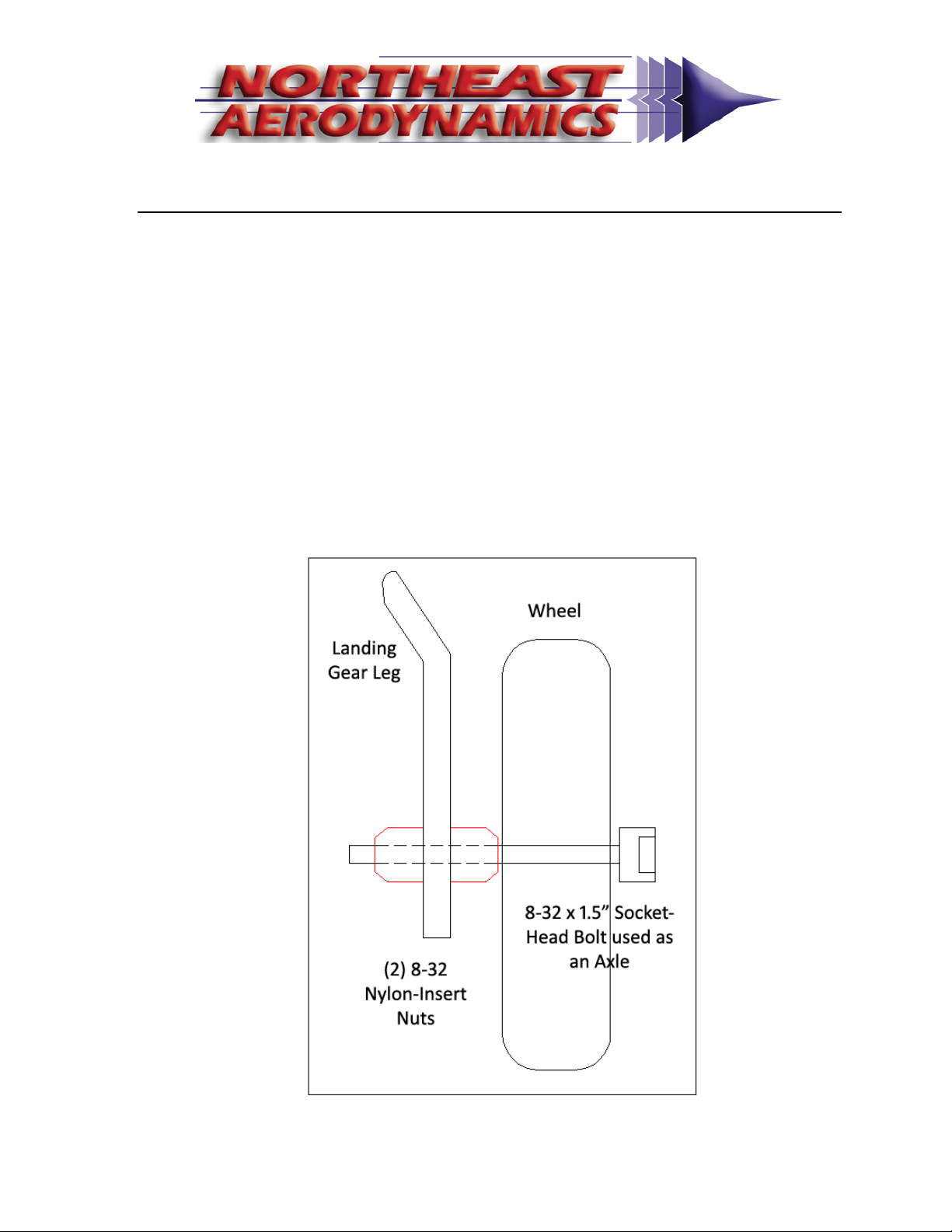
MountingtheWheelsandWheel‐Pants
1. Wehavefoundthatthesuppliedhardwareshouldbelookedatbutnot
usedformountingyourwheelsorwheelpantstotheAquila.We
recommendthatyouuse(2)8‐32x1.5”socketheadboltsand(4)8‐32
nyloninsertnutstomountyourwheelstothealuminumlandinggear
asdescribedbelow.
2. Inserttheboltthroughthecenterofyourwheel.Attachanyloninsert
nuttotheboltbackwards.Thiskeepstheflatsideofthenutawayfrom
thewheel.Tightenthisnutuntilyouareclosetothewheelandthe
wheelstillrotatesfreely.
3. Slidetheaboveassemblythroughtheholeinthelandinggearand
secureitwithanothernyloninsertnut(correctlyorientated).Tighten
thisnutuntiltheassemblyistightlyheldtothealuminumlandinggear.
- 16 -
4. Trialfityourwheelpantstothelandinggearwiththewheelalready
installed.Notethereisaleftwheelpantandarightwheelpant.You
willneedtocutaverticalslotintothewheelpantandplywoodinsertto
allowthewheeltoslipovertheaxle.Noteyouwillalsoneedtomake
theopeninginthewheelpantforthewheelslargertousethesupplied
wheels.Adjustasneededuntilthewheelpantslipsoneasilyandinto
thecorrectposition.
5. Settheplaneonitswheelsandadjusttheangleofthewheelpantsso
thatthewheelpanthasclearanceinthistake‐off/landingposture.
6. Usealong1/16”drillbitanddrillpilotholesintothewheelpantsusing
thepre‐drilledholesinthelandinggearasaguide.Useself‐taping
screwstolockthewheelpantsinplace.
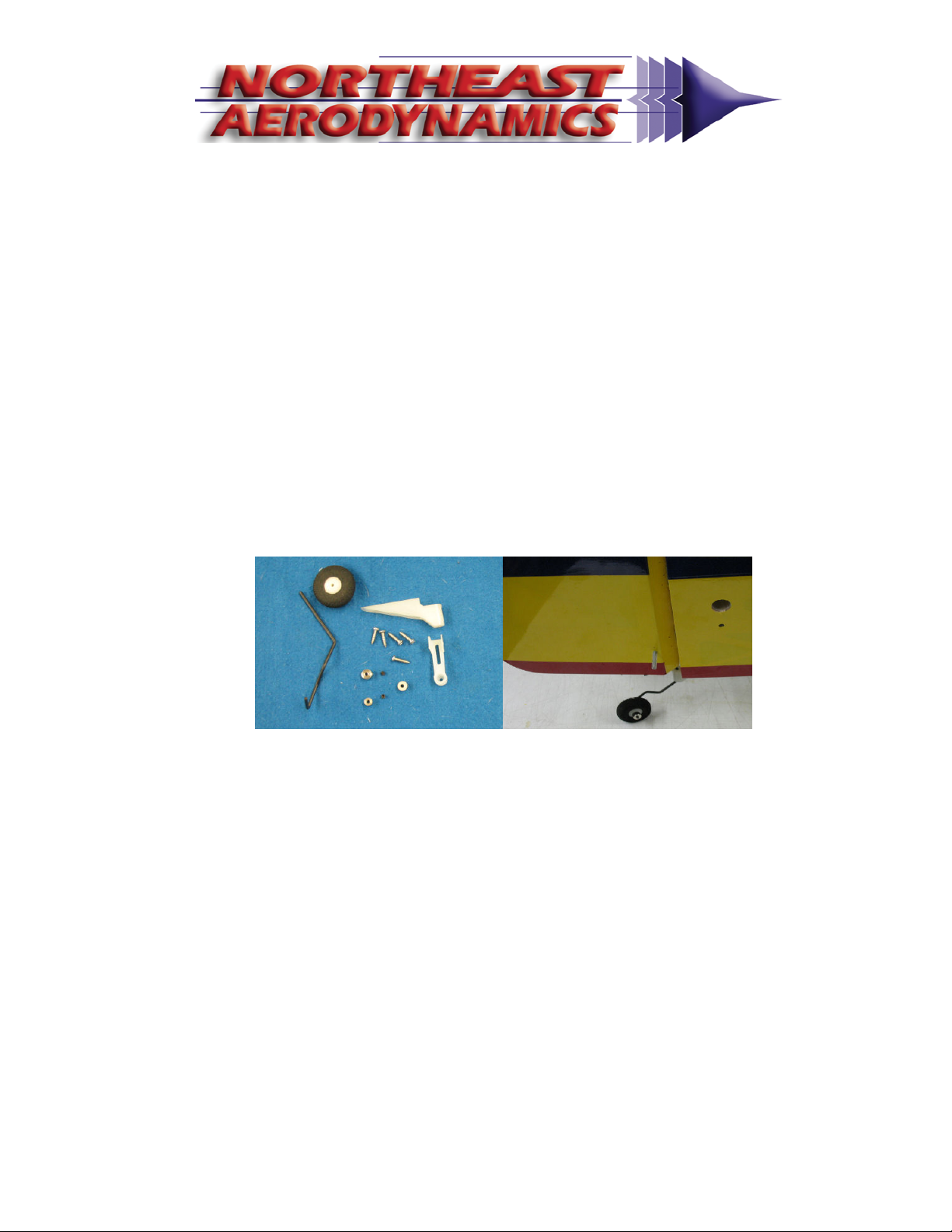
7. Mountthetailwheelwiththeprovidedhardware.
- 17 -
MountingCowl
1. Trialfitthecowlinplace.Notewherethemountingtabsextend
forwardofF1.
2. Carefullytapethecowlinplaceusingbluelow‐tackpainter’smasking
tapeandmarkwheretodrillpilotholesforthemountingscrews
3. Carefullydrill4pilotholes,onepertab,usinga1/16”drillbit.Then
removethecowl.
4. Enlargetheholesinthecowlslightly.Thiswillallowthescrewstopass
freelyinandoutofthecowl.
5. Enlargetheholesintheplywoodmountingtabstoallowa½”pieceof
yellowinnernyrod(notsupplied)tofitintotheholessnugly.Gluethe
yellownyrodintotheholeswithepoxyandensurethenyrodisflushto
theoutsideofthemountingtab(thisisthesidethatwillcomein
contactwiththecowl.
6. Beforemountingthecowl,useascrewandscrewitintoeachnyrod
endtoestablishthreadsontheinsideofthenyrod.

- 18 -
7. Reinstallthecowlandcarefullyseatthescrewsintothecenterofthe
nyrodandtakecarenottoallowthescrewstocutnewholesinthe
plywoodtabs.
8. Removethecowl.
- 19 -
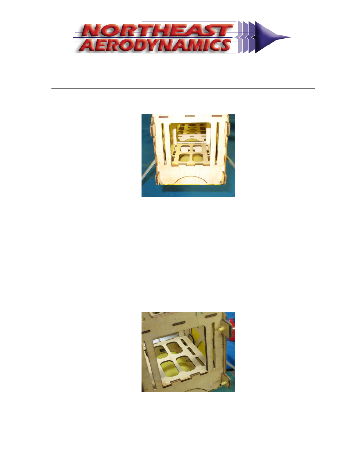
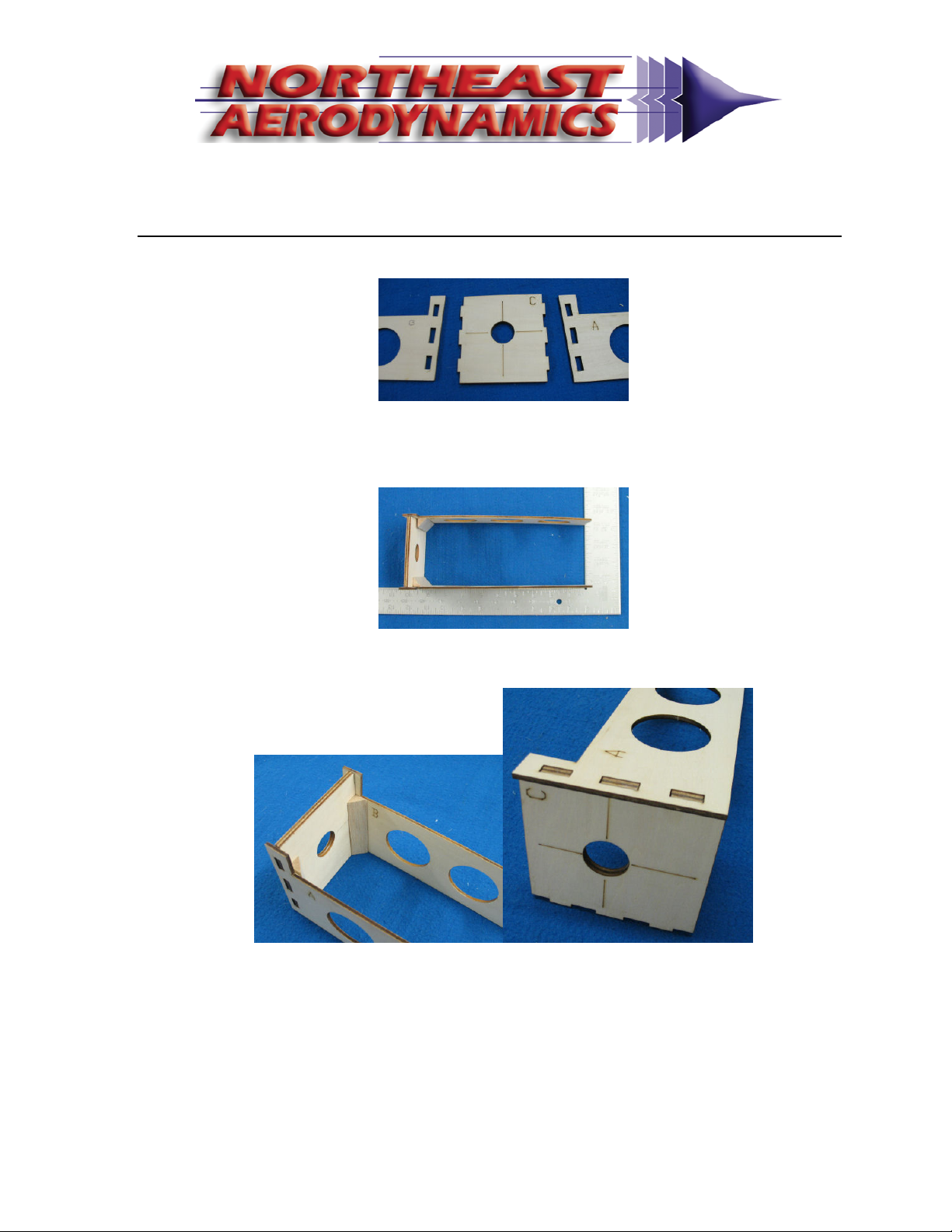
MountingYourEngine
1. Identifythepiecesofthefloatingfirewallassembly.
2. Usingabuildersquare,orothersquarecorner,assembleandalign
partsA,B,andC.NotetoobtaintheproperRight‐Thrustbothsides
mustbesquareasshown.
3. Gluethepiecestogetherusingepoxyandclampinplaceuntiltheepoxy
hascuredcompletely.Thenbracewiththetrianglestockprovided.

- 20 -
4. Youmightneedtoadjusttheopeningsinthefuselagetoallowthe
floatingfirewalltopassfreelythroughthepre‐cutslots.
5. Slidethefloatingfirewallintotheslotsandinstallyourenginemount.
Table of contents


