TROUBLESHOOTING
Contact Elenco Electronics if you have any problems. DO NOT contact your place of purchase as they will not
be able to help you.
-8-
OPERATING PROCEDURE
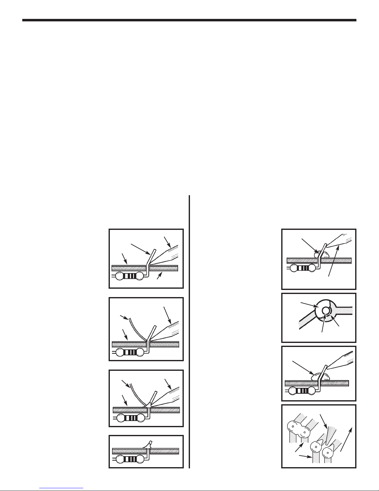
1. One of the most frequently occurring problems is
poor solder connections.
a) Tug slightly on all parts to make sure that they
are indeed soldered.
b) All solder connections should be shiny.
Resolder any that are not.
c) Solder should flow into a smooth puddle
rather than a round ball. Resolder any
connection that has formed into a ball.
d)
Have any solder bridges formed? A solder
bridge may occur if you accidentally touch an
adjacent foil by using too much solder or by
dragging the soldering iron across adjacent
foils. Break the bridge with your soldering iron.
2. Be sure that all components have been mounted
in their correct places.
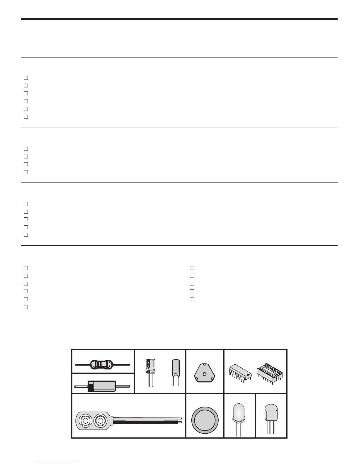
a) The LEDs will not light if they have not been
installed correctly. The flat side of the LEDs
should be in the same direction as marked on
the PC board.
b) Be sure capacitors C3 and C4 are installed
correctly. These capacitors are polarized so
be sure that the positive and negative leads
are in the correct hole as marked on the PC
board.
c) Be sure that ICs U1 and U2 are installed
correctly. The notch should be in the direction
shown on the PC board.
d) Be sure that transistor Q1 has been installed
correctly. The flat side of the transistor should
be in the same direction as marked on the PC
board.
e) Be sure that diode D1 is installed correctly.
The stripe on the diode should be on the
same side as the stripe marked on the PC
board.
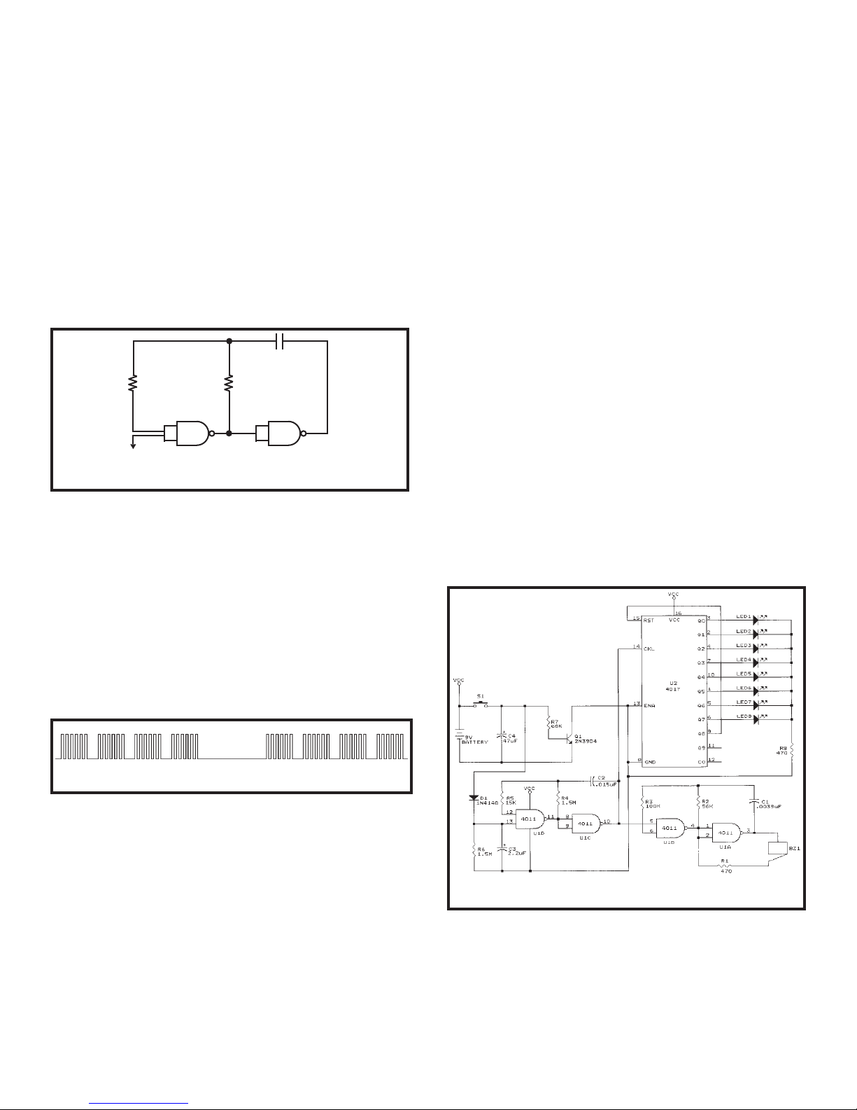
3. Use a fresh 9 volt ALKALINE battery.
4. NO SOUND AND NO LEDs
a) Check that the battery snap is wired as
shown on page 6 of this manual. The black
wire goes to J4 (–) and the red wire goes to
J3 (+).
b) Check that U1 and U2 are not installed
backwards. Be sure that there are no solder
bridges between the IC pins.
c) Check that the dimple switch is mounted with
the dome upward.
d) Check the value and the soldering of R7.
e) Check Q1.
5. CONTINUOUS SOUND AND LED
a) Check the wires in S1 and S2. They should
make contact with the dimple switch only
when the “ASK” ellipse on the red filter is
pressed.
6. LEDs BUT NO SOUND
a) Check that the buzzer is soldered as shown
in Figure H on page 7. Check the solder
connection between the jumper wire and the
center pad of the buzzer.
b) Check for soldering bridges between the pins
of U1.
c) Check the value and the soldering of R1, R2,
and R3.
7. LEDs STOP AS SOON AS THE SWITCH IS
RELEASED
a) Check that C3 and C4 are mounted with the
negative (–) lead in the hole marked on the
PC board.
b) Check the value and soldering of R6.
c) Check D1.
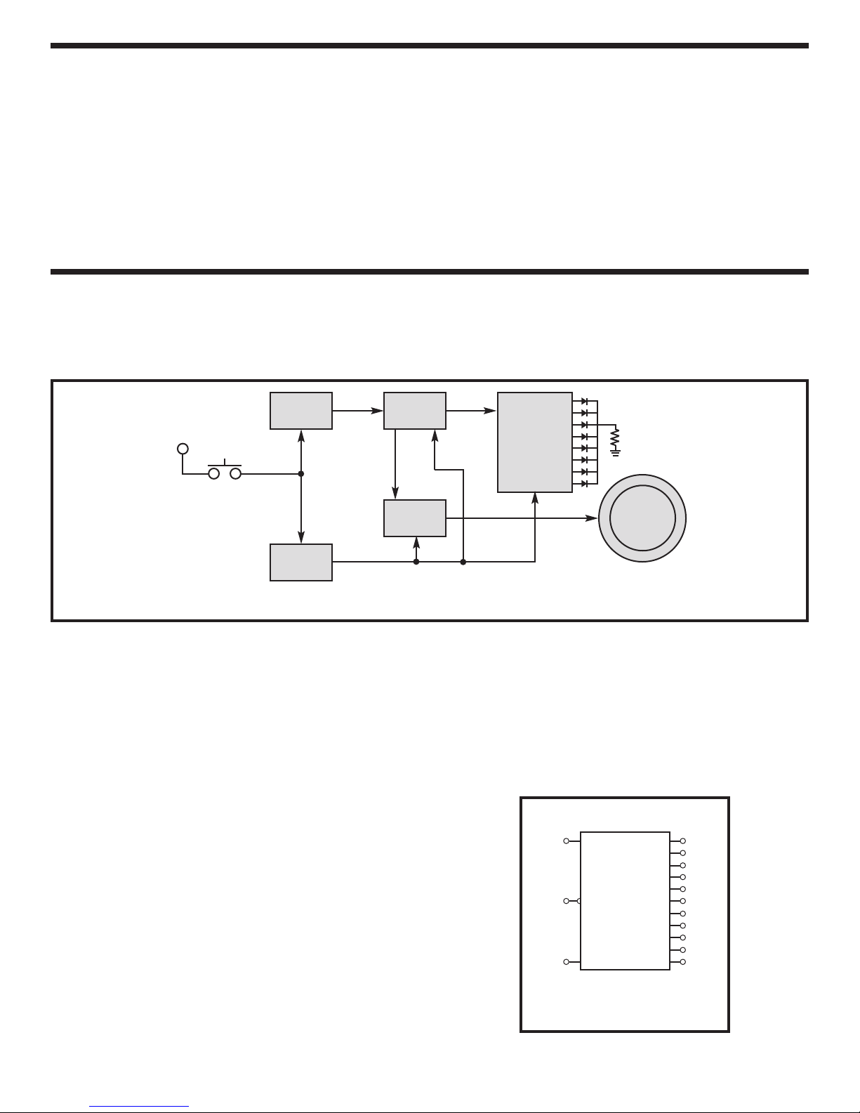
Operating your Decision Maker is very simple. Just
connect a 9 volt alkaline battery to the battery snap
and you are ready to go. Push the ASK button to get
your decision!