Northern Airborne Technology N301A-000 User manual
Northern Airborne Technology Ltd.
1925 Kirschner Road
Kelowna, BC, Canada.
V1Y 4N7
Telephone (250) 763-2232
Facsimile (250) 762-3374
Issued on the authority of Northern Airborne Technology Ltd.
Copyright 2004
Installation and Operation Manual
N301A-000
Audio Controller
COM3
COM4
COM5
COM2
NORM
EMER
ICS
TX RADIO ICS HOT VOX
DME
MKR
ADF1
ADF2
NAV1
NAV2
RX-ON
AUX
PVT
SM45
ISSUE 4.01


N301A-000 Audio Controller
SM45 Installation and Operation Manual
Installation and Operation Manual Page iii
ENG-FORM: 820-0114.DOT
CONFIDENTIAL AND PROPRIETARY TO NORTHERN AIRBORNE TECHNOLOGY LTD.
Table of Contents
Section Title Page
1. Description
1.1 Introduction 1-1
1.2 Product Description 1-1
1.3 Design Features 1-1
1.4 Specifications 1-1
1.4.1 Electrical Specifications 1-1
1.4.2 Physical Specifications 1-3
1.4.3 Environmental Specifications 1-3
2. Installation
2.1 Introduction 2-1
2.2 Unpacking and Inspection 2-1
2.2.1 Warranty 2-1
2.3 Continued Airworthiness 2-1
2.4 Installation Procedures 2-1
2.4.1 Warnings 2-1
2.4.2 Cautions 2-2
2.4.3 Cabling and Wiring 2-2
2.4.4 Installation Notes 2-3
2.4.5 Mechanical Mounting 2-3
2.4.6 Post Installation Checks 2-3
2.4.7 Tie Line Mode Options 2-4
2.5 Adjustments and Connections 2-4
2.5.1 Left Side Adjustments 2-5
2.5.2 Right Side Adjustments 2-5
2.6 Accessories Required But Not Supplied 2-6
2.7 Installation Drawings 2-6
3. Operation
3.1 Introduction 3-1
3.2 General Information 3-1
3.3 Controls and Indicators 3-1
3.3.1 Transmit Selection 3-1
3.3.2 Receive Audio 3-2
3.3.3 Emergency Switch (EMER/NORM) 3-2
3.3.4 ICS Functions 3-2
3.3.5 Direct Audio Inputs 3-3
3.3.6 Cockpit Voice Recorder 3-3

N301A-000 Audio Controller
SM45 Installation and Operation Manual
Section 1 Rev: 1.00 Issue 4 Page 1-1
ENG-FORM: 800-0114.DOT
CONFIDENTIAL AND PROPRIETARY TO NORTHERN AIRBORNE TECHNOLOGY LTD.
Section 1 Description
1.1 Introduction
Information in this section consists of product description, design features and specifications for the
N301A-000 Audio Controller. All derivative product information shall be contained in the applicable
manual supplement, which may be obtained from NAT as required.
Review all notes, warnings and cautions.
1.2 Product Description
The N301A is an Audio Controller that is compatible with military and civil aviation headsets. The N301A
controls the audio from multiple receivers, and allows transmission of mic audio to a selected transmitter.
Intercom operation is also provided, with two proprietary tie lines for system expansion. Three modes of
ICS are available: HOT; PTT; and VOX.
The N301A is a Dzus mounted audio panel with built in intercom. It provides full headset transmit and
receive functions for the user. The front panel level controls permit user adjustment of selected audio,
such as radio, ICS and VOX squelch.
The user has control of six transceiver positions, six receiver inputs, four direct audio alerts and two
different ICS tie lines.
The N301A is a drop-in replacement for the Andrea A301-6 audio panel.
1.3 Design Features
The N301A system employs NAT's unique audio processing, which reduces noise and tailors the
frequency response to produce clean, crisp intercom audio. Its high output power and low distortion
results in better on-board communication. The unit is designed to meet the requirements of TSO-C50c.
All inputs are fully floating including dedicated alerting inputs, except for the 150 ΩMic and ICS tie lines.
Independent RX and ICS volume controls are provided, and intercom mode can be varied from HOT MIC
through VOX to PTT (push to talk). In installations configured for the ‘Andrea’ tie lines, the ‘Private’ tie line
can also be used to provide secondary ICS for selected users. The NAT ICS tie line is fully compatible
with other NAT audio systems.
1.4 Specifications
1.4.1 Electrical Specifications
Power Supply:
Operating Voltage
Nominal 27.5 Vdc, with reverse and over voltage protection.
Maximum 30.3 Vdc
Minimum 24.8 Vdc
Emergency 20.0 Vdc

N301A-000 Audio Controller
SM45 Installation and Operation Manual
Section 1 Rev: 1.00 Issue 4 Page 1-2
ENG-FORM: 800-0114.DOT
CONFIDENTIAL AND PROPRIETARY TO NORTHERN AIRBORNE TECHNOLOGY LTD.
Input current 0.5 Amps Max.
Lighting 200 mA @ 27.5 Vdc
Input Signals
Quantity 12 receive channels
2 mic channels
4 direct channels
Audio level 4.5 Vrms for receiver inputs
0.25 Vrms for 150 Ωmic input
0.25 mVrms for 5 Ωmic input
4.5 Vrms for direct audio inputs
Impedance 10 kΩ±10% for receive inputs
150 Ω±10% for 150 Ωmic input
5 Ω±2 Ωfor 5 Ωmic input
10 kΩ±10% for direct audio inputs
Circuitry Type All are balanced inputs except for the 150 Ωmic (single ended)
Coupling < -60 dB input-to-input Crosstalk
Keylines Transmit PTT – active low
ICS PTT – active low
Output Signals:
Quantity 2 headset outputs
6 transmitter mic outputs
6 transmitter keyline outputs
1 mode of CVR output (Models -103 & -105 have 2 modes)
Rated level Hi impedance headset output >12.3 Vrms or 250 mW into 600 Ω
Low impedance headset output >1.42 V ms or 250 mW into 8 Ω
RX input CVR level - 1.4 Vrms ±10% into 5k Ω
Mic input CVR level - 0.45 Vrms ±50mV into 5k Ω
Mic output – 250 mVrms nominal into 150 Ω
Keyline outputs ≤1 A max. sink for mic keys
Circuitry Type Headsets and CVR are balanced outputs
Microphone outputs are single ended
Frequency Response Receive inputs <3 dB from 350 Hz to 6000 Hz
Direct inputs <3 dB from 350 Hz to 6000 Hz
Intercom <3 dB from 350 Hz to 3000 Hz
CVR output <3 dB from 350 Hz to 6000 Hz
Distortion <10% THD @ rated power output
Audio Noise Level Without Signal: >50 dB down from rated output
Coupling: <-55 dB input-to-output Crosstalk
Output Regulation <10% distortion / Δ3 dB max. of rated output power at 400% and 75% of
rated load

N301A-000 Audio Controller
SM45 Installation and Operation Manual
Section 1 Rev: 1.00 Issue 4 Page 1-3
ENG-FORM: 800-0114.DOT
CONFIDENTIAL AND PROPRIETARY TO NORTHERN AIRBORNE TECHNOLOGY LTD.
Bi-directional Signals:
Quantity: 3 ICS tie channels
Audio level: 0.34 Vrms for NAT ICS tie
2.8 Vrms for Interphone tie
2.8 Vrms for PVT ICS tie
Impedance: 1.6 kΩ±10% for NAT ICS tie input
19 kΩ±10% for Interphone ICS tie input
19 kΩ±10% for PVT ICS tie input
Circuitry Type: Single ended
Annunciators: Green LED illuminates for transmit operation
1.4.2 Physical Specifications
Height 2.64 inches (67.2 mm) max
Depth 3.40 inches (86.5 mm) max behind panel, excluding connector
Width 4.97 inches (126.3 mm) max behind panel
Weight 1.75 lbs (0.8 Kg) max excluding harness and mating connectors
Mounting Unit fits standard Dzus rails
Connectors Male 50-pin & 15-pin D-subminiature filtered connectors with Jackpost locks
Material/ Finish Chassis and cover are 5052-H32 brushed aluminum with chromate
conversion finish
Faceplate Laser etched acrylic edge-lit panel
1.4.3 Environmental Specifications
Temperature
Operating -20°C to +70°C
Survival -55°C to + 85°C
Altitude 25,000 feet max
Humidity 95% at 50°C 48 hours
Vibration/Shock RTCA/DO-160C Cat. MNY
Qualification of the N301A-000 Audio Controller was completed in accordance with:
B
RTCA/DO-160C Env. Cat. B4-BA[MNY]XXXXXXABABAZAXXX
Note: Refer to Environmental Qualification Form located in Section 2.7 of this Manual for complete
details of the environmental categories.

N301A-000 Audio Controller
SM45 Installation and Operation Manual
Section 1 Rev: 1.00 Issue 4 Page 1-4
ENG-FORM: 800-0114.DOT
CONFIDENTIAL AND PROPRIETARY TO NORTHERN AIRBORNE TECHNOLOGY LTD.
1.4.4 Product Approval
FAA: TSO-C50c (RTCA/DO-170, Class 1b)
Applicable to units serial number 3000 and above
Section 1 ends

N301A-000 Audio Controller
SM45 Installation and Operation Manual
Section 2 Rev: 1.00 Issue 4 Page 2-1
ENG-FORM: 805-0117.DOT
CONFIDENTIAL AND PROPRIETARY TO NORTHERN AIRBORNE TECHNOLOGY LTD.
Section 2 Installation
2.1 Introduction
Information in this section consists of unpacking and inspection procedures, installation procedures, post-
installation checks and installation drawings for the N301A-000 Audio Controller.
Review all notes, warnings and cautions.
2.2 Unpacking and Inspection
Unpack the equipment carefully and locate the warranty card. Inspect the unit visually for damage due to
shipping and report all such claims immediately to the carrier involved. Check that all items listed below
are present before proceeding and report any shortage immediately to your supplier:
- Warranty Card
- Operators Manual
- Certificate of Conformity or Release Certification
2.2.1 Warranty
All Northern Airborne Technology Ltd. products are warranted for 2 years from date of installation by an
authorized NAT dealer, to be free of defects in workmanship or performance. This warranty covers all
materials and labour, but is exclusive of any transport to deliver the defective unit to and from NAT or its
designated warranty repair center, or any labour to remove or re-install the defective unit in the aircraft.
Contact NAT for any questions regarding this warranty, its applicability to your units and/or for return
authorization. NAT is the final arbitrator concerning warranty administration. Units which have been
physically damaged, burned, immersed in water or otherwise abused beyond the scope of normal use will
not be considered for warranty. WARRANTY IS VOID UNLESS THE PRODUCT IS INSTALLED BY AN
AUTHORIZED NAT DEALER. Product for which a warranty card is not returned shall be warranted from
date of manufacture.
2.3 Continued Airworthiness
Maintenance of the N301A-000 Audio Controller is ‘on condition’ only. Periodic maintenance of this
product is not required.
2.4 Installation Procedures
2.4.1 Warnings
WARNING:
High volume settings can cause hearing damage.
Set the headset volume control to the minimum volume setting prior to
conducting tests, and slowly increase the headset volume to a
comfortable listening level.

N301A-000 Audio Controller
SM45 Installation and Operation Manual
Section 2 Rev: 1.00 Issue 4 Page 2-2
ENG-FORM: 805-0117.DOT
CONFIDENTIAL AND PROPRIETARY TO NORTHERN AIRBORNE TECHNOLOGY LTD.
2.4.2 Cautions
CAUTION:
Do not bundle any lines from this unit with transmitter coax feedlines. Do not
bundle any logic, audio, or DC power lines from this unit with 400 Hz synchro
wiring or AC power lines. Do not position this unit next to any device with a
strong alternating magnetic field such as an inverter, motor or blower, or
significant audio interference will result.
The length and routing of the mic wire is very critical. Unwanted signal
coupling will result from the mic wiring being bundled with high level audio
lines (i.e. phones or radio audio lines). The longer the wire, the greater the
level of coupling of unwanted audio onto the mic wires.
In all installations, use shielded cable exactly as shown, and ground only as
indicated. Significant problems may result from not following these guidelines.
All audio installations can be seriously degraded by incorrect wiring and
shielding, and may result in abnormal cross-talk, hum and ground-loop noise.
Be especially careful with all microphone wiring and tie line wiring, as these
lines carry the lowest level signals in the aircraft.
2.4.3 Cabling and Wiring
All wire shall be selected in accordance with the original aircraft manufacturer's Maintenance Instructions
or AC43.13-1B Change 1, Paragraphs 11-76 through 11-78. Unshielded wire types shall qualify to
MIL-W-22759 as specified in AC43.13-1B Change 1, Paragraphs 11-85, 11-86, and listed in Table 11-11.
For shielded wire applications, use Tefzel MIL-C-27500 shielded wire with solder sleeves (for shield
terminations) to make the most compact and easily terminated interconnect. Follow the connector map in
Section 2.7 as required.
Allow 3" from the end of the shielded wiring to the shield termination to allow the connector hood to be
easily installed. Reference the interconnect drawing in Section 2.7 for shield termination details. Note that
the hood is a "clamshell" hood, and is installed after the wiring is complete. Aircraft harnessing shall
permit the unit to be removed from the panel for easy access to all side adjustments. Do NOT mount the
unit until all adjustments have been performed.
Maintain wire segregation and route wiring in accordance with the original aircraft manufacturers
Maintenance Instructions.
Unless otherwise noted, all wiring shall be a minimum of 22 AWG, except power and ground lines, which
shall be a minimum of 20 AWG. Refer to the Interconnect drawing for additional specifications. Check that
the ground connection is clean and well secured, and that it shares no path with any electrically noisy
aircraft accessories such as blowers, turn and bank instruments or similar loads. Power to this unit must
be supplied from a separate circuit breaker or fuse (fast blow), and not attached to any other circuit
breaker without additional protection. Verify that the selected circuit breaker size and wire gauge are
adequate for the installation using the techniques specified in AC43.13-1B Change 1, Paragraphs 11-47
through 11-51 and 11-66 through 11-69.

N301A-000 Audio Controller
SM45 Installation and Operation Manual
Section 2 Rev: 1.00 Issue 4 Page 2-3
ENG-FORM: 805-0117.DOT
CONFIDENTIAL AND PROPRIETARY TO NORTHERN AIRBORNE TECHNOLOGY LTD.
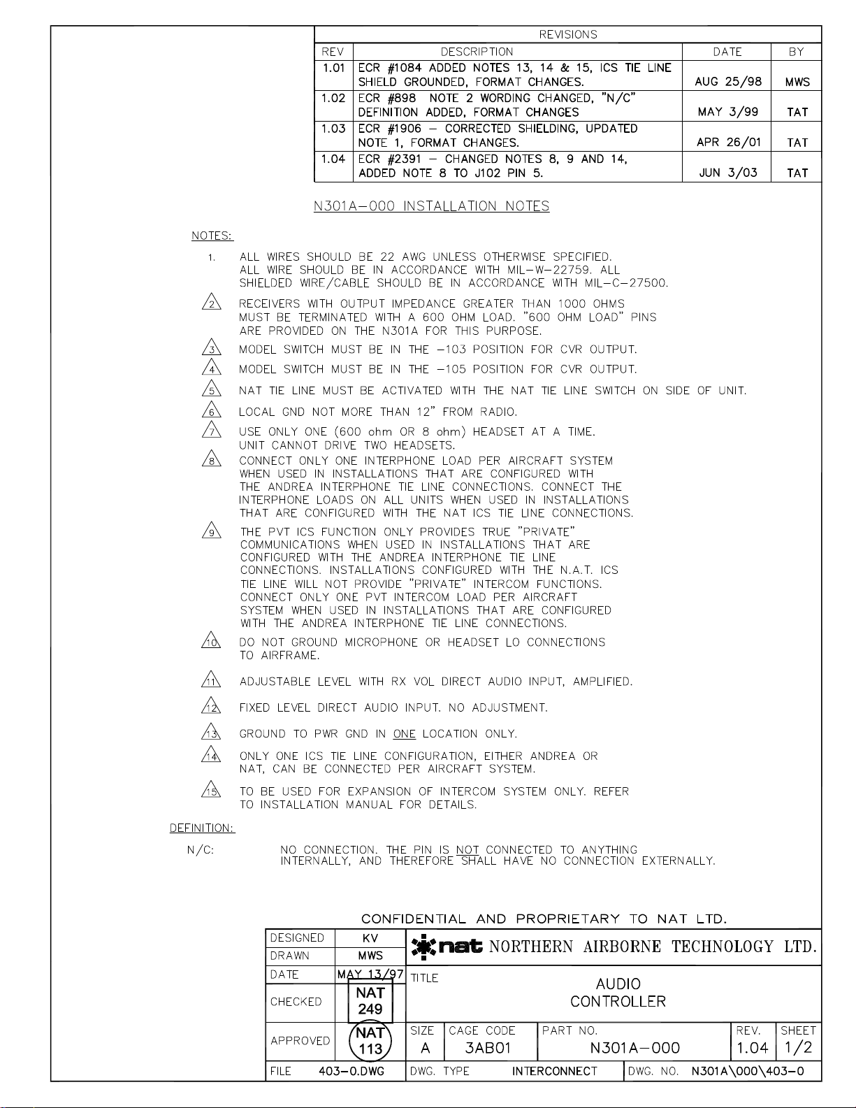
2.4.4 Installation Notes
Follow instructions on installation drawings in section 2.7. If the receivers have very high output
impedance (great than 1000 ohms), they should be terminated with the internal load resistors. Four
600 Ωand two 150 Ωresistors are provided in each N301A-000 controller; only use one load resistor per
radio in the system.
The intercom tie lines and PVT tie lines should be also properly terminated with a load resistor.
Connect only one interphone load per aircraft system when used in installations that are configured with
Andrea interphone tie line connections. Connect the interphone loads on all units when used in
installations that are configured with the NAT ICS tie line connections.
The PVT ICS function only provides true ‘private’ communications when used in installations that are
configured with the Andrea interphone tie line connections. Installations configured with the NAT ICS tie
line will not provide ‘private’ intercom functions. Connect only PVT intercom load per aircraft system when
used in installations that are configured with the Andrea interphone tie line connections.
Only one ICS tie line configuration, either Andrea or NAT, can be connected per aircraft system.
Note: All AA95/AMS4X Audio Controllers with S/N: 1918 or before used with the N301A-000 must have
the ICS Tie and Gain Modifications installed, or impaired intercom audio between units will result.
2.4.5 Mechanical Mounting
The N301A-000 can be mounted vertically or horizontally in standard Dzus rails.
Before the unit is mounted, make all functional tests, and trimpot adjustments. Be sure the harness has
enough clearance to permit the unit to be pulled out for re-adjustment, if needed later. Make sure the unit is
securely fastened to the Dzus rail, and that the connector locks are tightened before any flight is attempted.
2.4.6 Post Installation Checks
2.4.6.1 Voltage/Resistance Checks
Do not attach the N301A until the following conditions are met.
Check the following:
a) J101 pin <12> for +28 Vdc relative to ground.
b) J101 pin <11> for 0.5 Ωto ground.
2.4.6.2 Power On Checks
Power up the aircraft’s systems and confirm normal operation of all functions of the N301A. Refer to
Section 3 (Operation) for specific operational details.
a) Install the N301A-000 and power up the ship’s systems. Turn on the radios and accessories
required for the system.
b) Check for correct radio audio and adjust for acceptable level.

N301A-000 Audio Controller
SM45 Installation and Operation Manual
Section 2 Rev: 1.00 Issue 4 Page 2-4
ENG-FORM: 805-0117.DOT
CONFIDENTIAL AND PROPRIETARY TO NORTHERN AIRBORNE TECHNOLOGY LTD.
c) Run through all installed functions, and check the ICS and TX functions for all users. See section 3
for specific operation details.
Notes:
1) Significantly different headsets may have different mic characteristics
2) The David Clark M-7 mic is much more active than their M-4 or M-1 microphones,andmay
aggravate headset imbalance if used in a mixed system.
d) If any preset requires adjustment, be sure this is carried out before the aircraft leaves, and that
the unit and its mating connector are secured before departure. Make all required log book
entries, electrical load, weight and balance amendments and other paperwork as required by your
local regulatory agency.
Upon satisfactory completion of all performance checks, make all required log book entries, electrical
load, weight and balance amendments and other documentation as required by your local regulatory
agency before releasing the aircraft for service.
2.4.7 Tie Line Mode Options
The tie line options can be selected using the right side adjustments - see section 2.5.2.
Note: The PVT ICS selection is not supported by the NAT tie line options - see section 3.3.4.4.
2.4.7.1 Andrea Tie line
The Andrea tie line option permits the use of up to ten individual boxes, but can support only one active
user at a time because of loading considerations. If all users are in ‘live’ mode there will be a significant
decrease in ICS audio level. See also section 3.6.3.
2.4.7.2 One NAT ICS Line
This option should be selected when two NAT audio controllers are tied together.
2.4.7.3 Two NAT ICS Lines
This option should be selected when three or more controllers are to be tied together. After three boxes
are connected together, the audio ICS level will degrade. NAT do not recommend that more than four
NAT boxes be tied together using the ICS tie line.
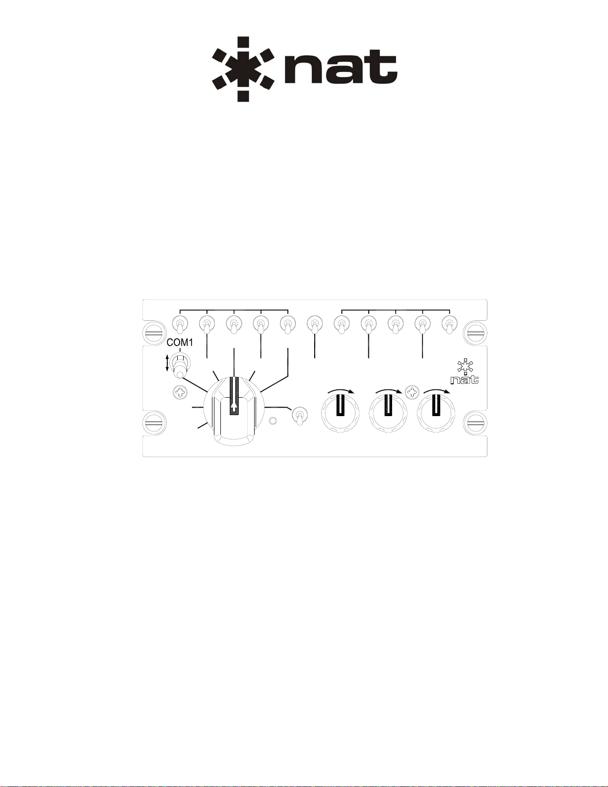
2.5 Adjustments and Connections
The unit is shipped from the factory with all internal adjustments set to the normal test levels. Once
installed in the aircraft, it may be desirable to change some of these settings to best suit the local
operating environment.
The internal adjustments that can be varied are located along the sides of the unit (refer to drawing
N301A\000\922-0) and are as follows:
N301A-000 Audio Controller
SM45 Installation and Operation Manual
Section 2 Rev: 1.00 Issue 4 Page 2-5
2.5.1 Left side Adjustments
CVR OUT LEVEL Adjusts level of the summed received audio, direct audio, and
intercom audio fed to the cockpit voice recorder. Fully ccw is
minimum and fully cw is maximum.
TRANSMIT MIC LEVEL Six controls (COM1-5, AUX) which adjust the mic output level to
the respective radios. Fully ccw is minimum and fully cw is
maximum.
MODEL (103/105) A slide switch allows selection of the required variant. With this
switch at position 103, the unit simulates the AndreaA301-103,
and at 105 it simulates the A301-105. (See N301A-000\403-0
interconnect for more details.)
CAUTION:
The MODEL (103/105) switch determines the internal configuration for the
CVR output, and is installation specific. This switch must be set to the
appropriate position to match the wiring configuration in the aircraft. Failure to
set the switch to the correct position will result in no audio being delivered to
the respective recording input on the CVR. Refer to the N301A\000\403
interconnect diagram located in section 2.7 for more information.
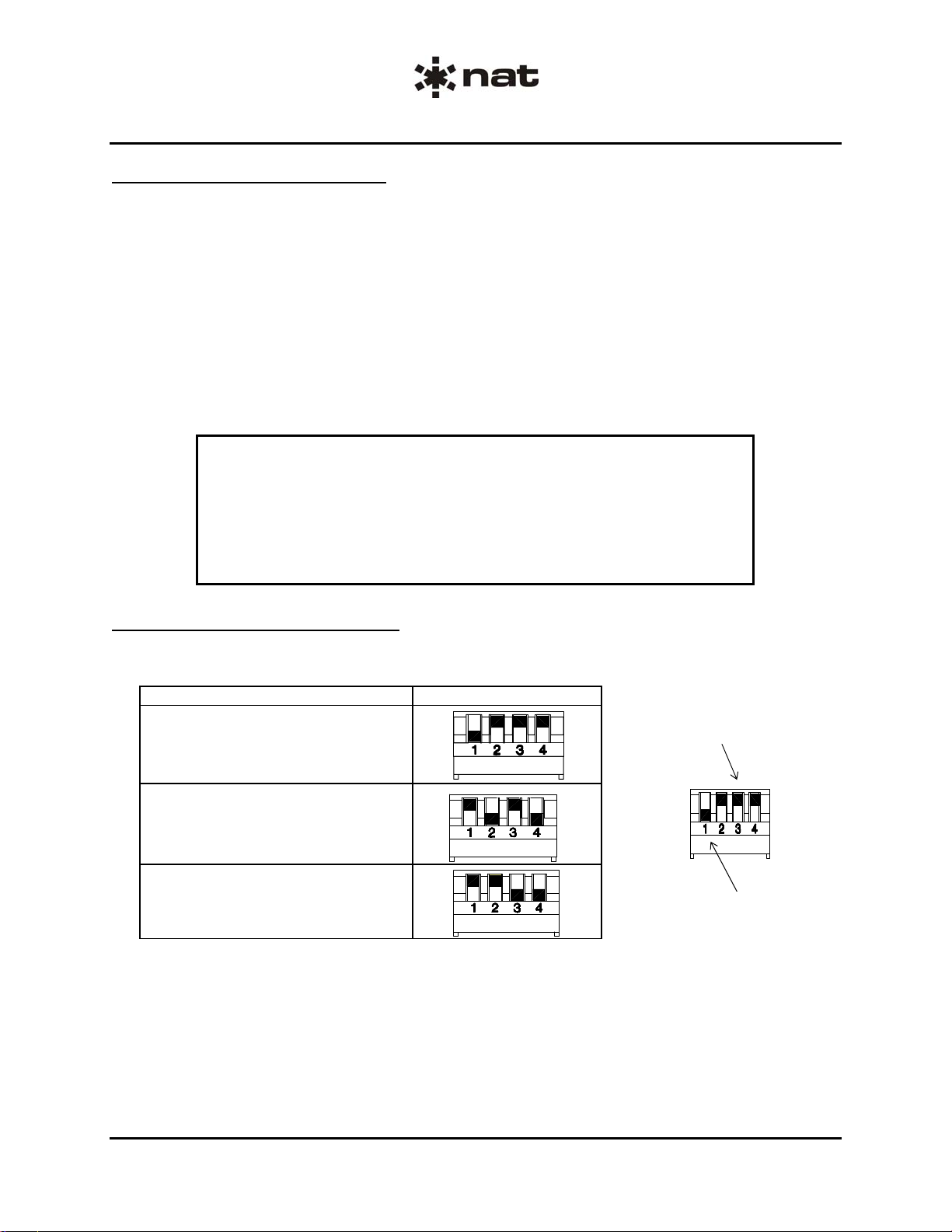
2.5.2 Right Side Adjustments
TIE LINE MODE Selects the tie line option. (see figure 1 below).
ENG-FORM: 805-0117.DOT
CONFIDENTIAL AND PROPRIETARY TO NORTHERN AIRBORNE TECHNOLOGY LTD.
TIE LINE MODE Selection Switch Positions
ANDREA Tie Lines
1 NAT ICS
2 NAT ICS
Switches 2, 3 and 4
in ‘UP’ position
(Open or Off)
Switch 1 in ‘DOWN’ position
(Closed or On)
Tie Line Mode Switch Configurations - figure 1
a) ANDREA Tie Lines: TIE LINE MODE switch 1 DOWN, switches 2, 3 and 4 UP
b) 1 NAT ICS Tie Line: TIE LINE MODE switches 2 and 4 DOWN, switches 1 and 3 UP
c) 2 NAT ICS Tie Lines: TIE LINE MODE switches 3 and 4 DOWN, switches 1 and 2 UP

N301A-000 Audio Controller
SM45 Installation and Operation Manual
Section 2 Rev: 1.00 Issue 4 Page 2-6
ENG-FORM: 805-0117.DOT
CONFIDENTIAL AND PROPRIETARY TO NORTHERN AIRBORNE TECHNOLOGY LTD.
2.6 Accessories Required But Not Supplied
Installation kit p/n N301A-IKC (crimp) is required to complete the installation. The kit consists of one 50
Pin D-min Female Crimp Kit (D50SL-IKC) and one 15 Pin D-min Female Crimp Kit (D15SL-IKC)
The 50 Pin D-min Female Crimp Kit (D50SL-IKC) consists of:
Quantity Description NAT Part No.
1 D-min 50 Socket Housing 20-21-050
50 MS Crimp Socket 20-26-901
1* Jack Screw Set 20-27-002
1* Lock Clip Set 20-27-004
1 50 Pin Connector Hood 20-29-051
The 15 Pin D-min Female Crimp Kit (D15SL-IKC) consists of:
Quantity Description NAT Part No.
1 D-min 15 Socket Housing 20-21-015
15 MS Crimp Socket 20-26-901
1* Jack Screw Set 20-27-002
1* Lock Clip Set 20-27-004
1 15 Pin Connector Hood 20-29-015
* Use as required.
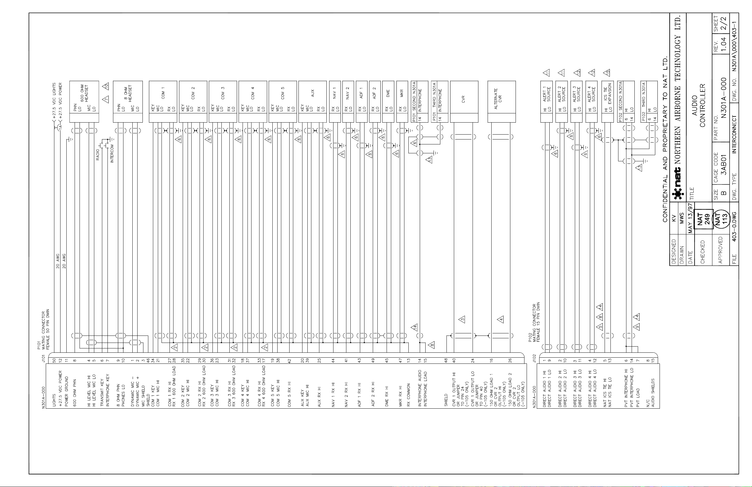
2.7 Installation Drawings
DRAWING REV. DESCRIPTION TYPE SERIAL No.
N301A\000\403-0 1.04 N301A Audio Controller Interconnect All
N301A\000\403-1 1.04 N301A Audio Controller Interconnect All
N301A\000\405-0 1.01 N301A Audio Controller Connector Map All
N301A\000\521-0 1.10 N301A Audio Controller Environmental Qual Form 3000 and up
N301A\000\905-0 1.20 N301A Audio Controller Faceplate (sheet 1) All
N301A\000\922-0 1.01 N301A Audio Controller Mech Installation 2000 to 2129
N301A\000\922-0 1.10 N301A Audio Controller Mech Installation 2130 to 2999
N301A\000\922-0 1.20 N301A Audio Controller Mech Installation 3000 and up
Section 2 ends following the above documents


COM3
COM4
COM5
COM2
NORM
EMER
ICS
TX RADIO ICS HOT VOX
DME
MKR
ADF1
ADF2
NAV1
NAV2
RX-ON
AUX
PVT
COM3
COM4
COM5
COM2
NORM
EMER
ICS
TX RADIO ICS HOT VOX
DME
MKR
ADF1
ADF2
NAV1
NAV2
RX-ON
AUX
PVT
This manual suits for next models
1
Table of contents
Other Northern Airborne Technology Recording Equipment manuals


Popular Recording Equipment manuals by other brands

AtomoSynth
AtomoSynth TOTTEM 2 quick start guide

ETS
ETS SMEA-1 instructions

Pioneer
Pioneer GR-777 operating instructions

Weinzierl
Weinzierl KNX IP Interface 731 Operation and installation manual

Rainger FX
Rainger FX ECHO-X user manual

Avid Technology
Avid Technology Pro Tools S6 Master Post Module Assembling/disassembling


