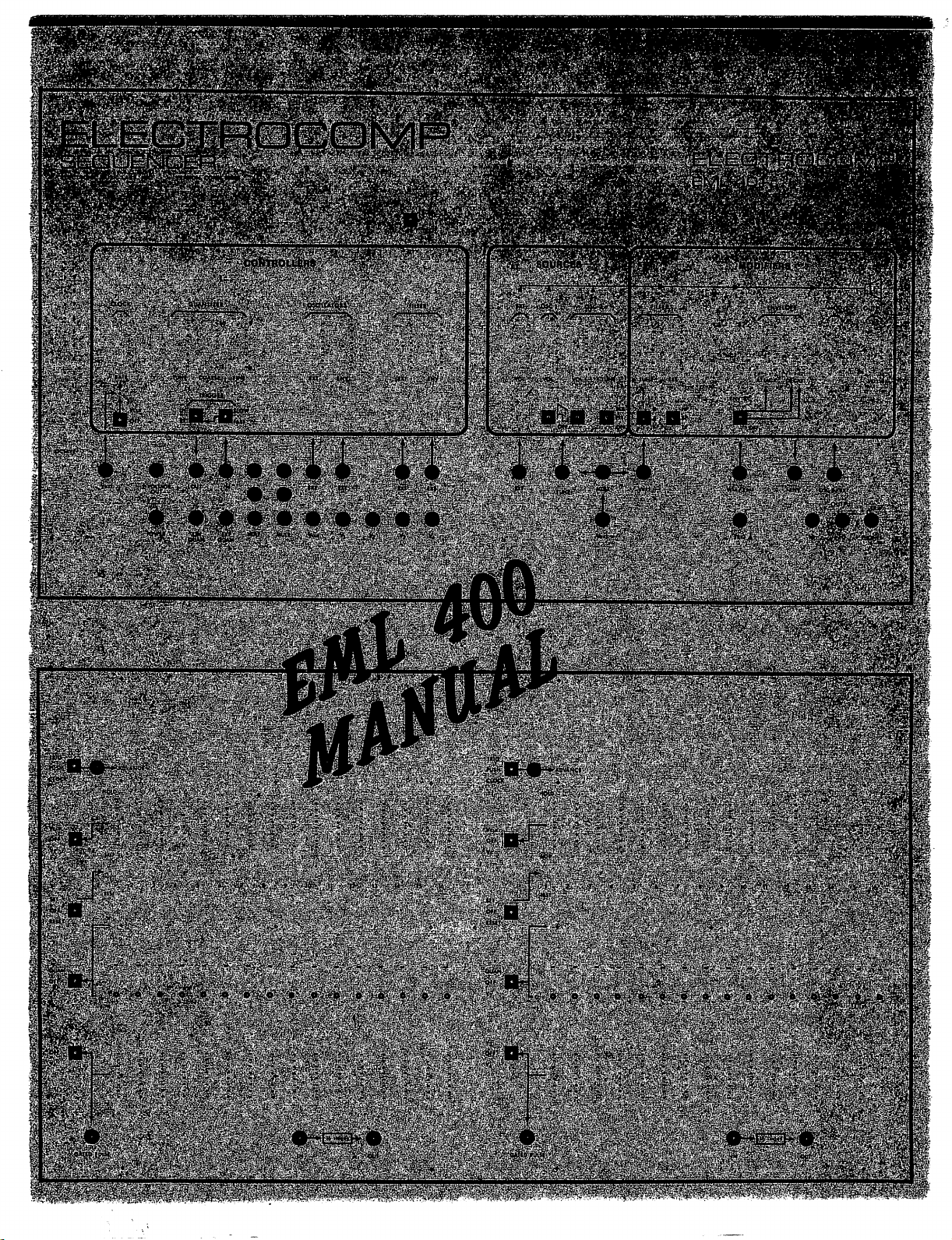
EML ELECTROCOMP 400 Series User manual
Scan by Manual Manor
http://www.markglinsky.com/ManualManor.html
EML
400
SERIES
SEQUENTIAL
SYNTHESIZER
MANUAL
The
EML
400
Series
Sequential
Synthesizer
is
available
in
several
config
urations
to
permit
each
user
a
maximum
of
flexibility.
A
basic
sequencer
consists
of
the
following:
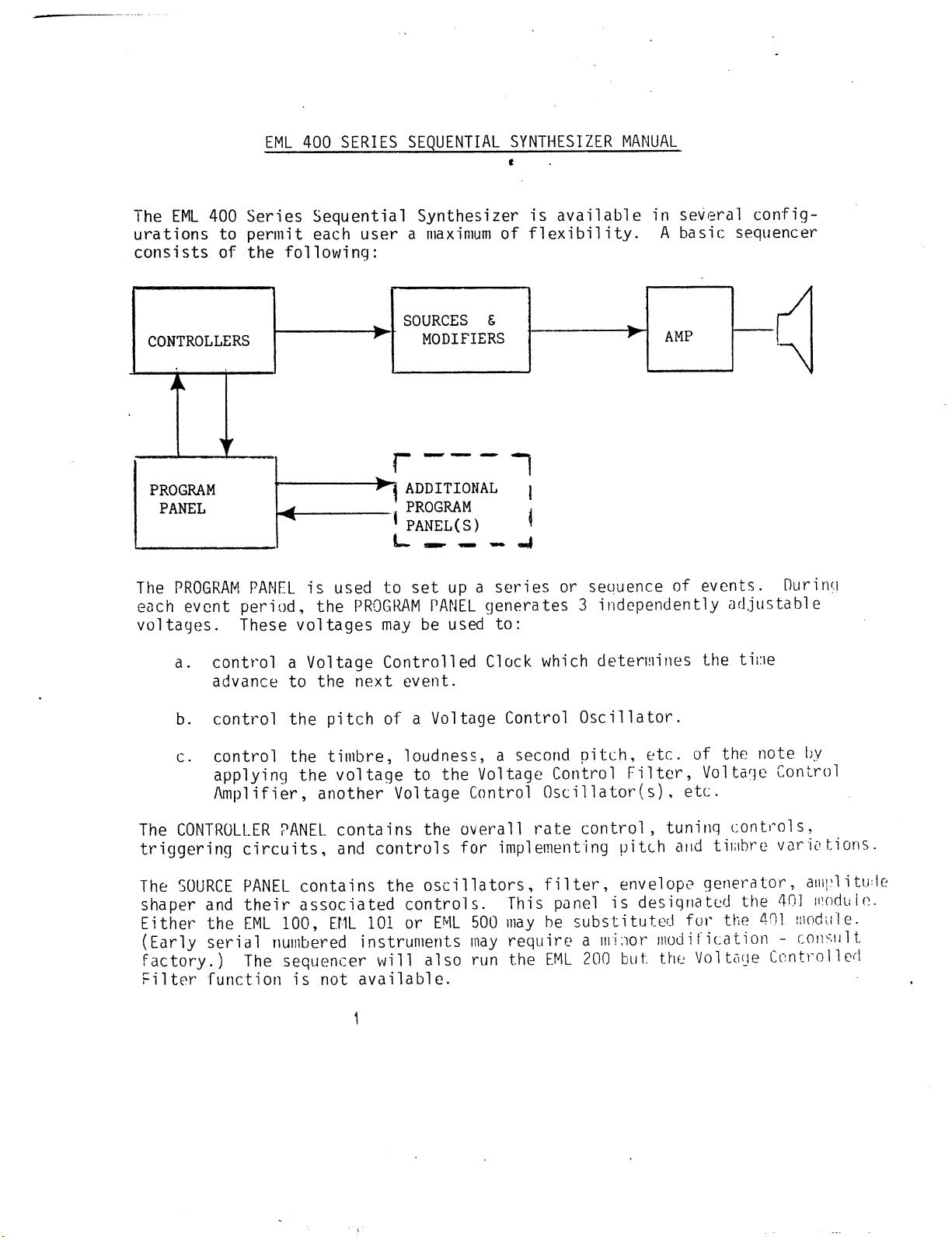
CONTROLLERS
PROGRAM
PANEL
SOURCES
S
MODIFIERS
i
1
Tj
ADDITIONAL
j
.
PROGRAM
,
'
PANEL(S)
'
L_
^^
M.
,j
The
PROGRAM
PANEL
is
used
to
set
up
a
series
or
sequence
of
events.
During
each
event
period,
the
PROGRAM
PANEL
generates
3
independently
adjustable
voltages.
These
voltages
may
be
used
to:
a.
control
a
Voltage
Controlled
Clock
which
determines
the
tine
advance
to
the
next
event.
b.
control
the
pitch
of
a
Voltage
Control
Oscillator.
c.
control
the
timbre,
loudness,
a
second
pitch,
etc.
of
the
note
by
applying
the
voltage
to
the
Voltage
Control
Filter,
Voltage
Control
Amplifier,
another
Voltage
Control
Oscillator(s),
etc.
The
CONTROLLER
PANEL
contains
the
overall
rate
control,
tuning
controls,
triggering
circuits,
and
controls
for
implementing
pitch
and
timbre
variations.
The SOURCE
PANEL
contains
the
oscillators,
filter,
envelope
generator,
amplitude
shaper
and
their
associated
controls.
This
panel
is
designated
the
401
modulo.
Either
the
EML
100,
EML
101
or
EML
500
may
be
substituted
fur
the 401
module.
(Early
serial
numbered
instruments may
require
a
minor
modification
-
consult
factory.)
The
sequencer
will
also
run
the EML
200
but
the
Voltage
Controlled
Filter
function
is
not
available.
1
Scan by Manual Manor
http://www.markglinsky.com/ManualManor.html

GENERAL
MODULE
DESCRIPTION:
I.
PROGRAM
PANEL
1.
ADVANCE
SLIDE
SWITCH
This
slide
switch
determines
how the
sequence
advances
from
stage
to
stage.
A.
TRIGGER:
sequence
will
advance
from
trigger
pulse
corresponding
to
the
output
of
the
trigger
function
on
controller
panel.
B.
PUSH:
sequence
will
advance
when
pushbutton
is
depressed.
C.
CLOCK:
sequence
will
advance
under
control
of
the
clock.
Scan by Manual Manor
http://www.markglinsky.com/ManualManor.html
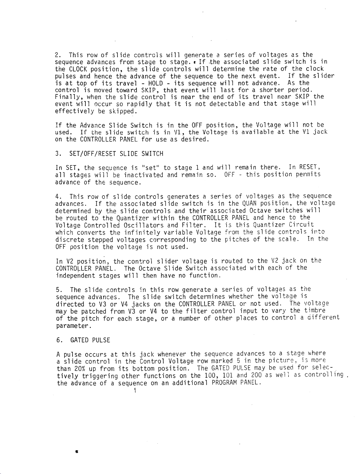
2.
This
row
of slide
controls
will
generate
a
series
of
voltages
as
the
sequence
advances
from
stage
to
stage.
«
If
-the
associated
slide
switch
is in
the
CLOCK
position,
the
slide
controls
will
determine
the
rate
of
the
clock
pulses
and
hence
the
advance
of
the
sequence
to
the
next
event.
If
the
slider
is
at
top
of
its
travel
-
HOLD
-
its
sequence
will
not
advance.
As
the
control
is
moved
toward
SKIP,
that
event
will
last for
a
shorter
period.
Finally,
when
the
slide
control
is
near
the
end
of
its
travel
near
SKIP
the
event
will
occur
so
rapidly
that
it
is
not
detectable
and
that
stage
will
effectively
be
skipped.
If
the
Advance
Slide
Switch
is
in
the
OFF
position,
the
Voltage
will
not
be
used.
If
the
slide
switch
is
in
VI,
the
Voltage
is
available
at
the
VI
jack
on
the
CONTROLLER
PANEL
for
use
as
desired.
3.
SET/OFF/RESET
SLIDE
SWITCH
In
SET, the
sequence
is
"set"
to
stage
1
and
will
remain
there.
In
RESET,
all
stages
will
be
inactivated
and
remain
so.
OFF
-
this
position
permits
advance
of the
sequence.
4.
This
row
of
slide
controls
generates
a
series
of
voltages
as
the
sequence
advances,
If
the
associated
slide
switch
is
in
the
QUAN
position,
the
voltage
determined
by
the
slide
controls
and
their
associated
Octave
switches
will
be
routed
to
the
Quantizer
within
the
CONTROLLER
PANEL
and
hence
to
the
Voltage
Controlled
Oscillators
and
Filter.
It
is
this
Quantizer
Circuit
which
converts
the
infinitely
variable
Voltage
from
the
slide
controls
into
discrete
stepped
voltages
corresponding
to
the
pitches
of
the
scale.
In
the
OFF
position
the
voltage
is
not
used.
In
V2
position,
the
control
slider
voltage
is
routed
to
the
V2
jack
on
the
CONTROLLER
PANEL.
The
Octave
Slide
Switch
associated
with
each
of
the
independent
stages
will
then
have
no
function.
5.
The
slide
controls
in
this
row
generate
a
series
of
voltages
as
the
sequence
advances.
The
slide
switch
determines whether
the
voltage
is
directed
to
V3
or
V4
jacks
on
the
CONTROLLER
PANEL
or
not
used.
The
voltage
may
be
patched
from
V3
or
V4
to
the
filter
control
input
to
vary
the
timbre
of the
pitch
for
each
stage,
or
a
number
of
other
places
to
control
a
different
parameter.
6.
GATED
PULSE
A
pulse
occurs
at
this
jack
whenever
the
sequence
advances
to
a
stage where
a
slide
control
in
the
Control
Voltage
row
marked
5
in
the
picture,
is
more
than
20%
up
from
its
bottom
position.
The
GATED
PULSE
may
be
used
for
selec-
.
tively
triggering
other
functions
on the
100,
101
and
200
as
well
as
controlling
the
advance
of
a
sequence
on
an
additional
PROGRAM
PANEL.
1
Scan by Manual Manor
http://www.markglinsky.com/ManualManor.html
7.
16
STAGES
IN-OUT
In,t,hI;HK.
li
"1°°P"
the
sec>uence-
If
one
program
panel
is
used,
i
n
tt"66"
thG
two
J?cks
wil1
caus*
the
16th
stage
to
trigger
the
first
so
that
the
sequence
will
repeat.
No
patchcord
-
no
repeat.
PANEITS
are
avai>1ab^
a
patchcord
is
used
between
the
hP
OUT
^
rTtEane1
^
thG
IN
jack
°f
the
Second
PR0GRAM
PANEI-
and
win
ihL
22
°!
55e SGC°nd
t0
the
IN
jack
of
the
first-
The
sequencer
will
then
go
through
32
stages
before
repeating.
H
8.
EXPAND
PLUG1.
?
t0
thG
C0NTR0LLER
PANEL
through
the
cable
provided;
Jo
ethPr
PRnrRAMin?
Pane\l'
lhe
Cable
from
the
CONTROLLER
PANEL
may
g
tLVlS
k
i
connector-
If
^^e
are
more
than
2
Programming
Panels,
they
must
be
interconnected
with
an
additional
cable.
II
CONTROLLER
PANEL
I?
ij
3.
ELECTROCOMP
SEQUENCER
£lf
CTRONIC
MUSIC
tAM..
.NC.
VCRNON.
CONN.
MOM
2.
1.
V
4.
Scan by Manual Manor
http://www.markglinsky.com/ManualManor.html
EML 401
MODULE
-
SOURCES
AND MODIFIERS
PANEL
SOURCES
The
EXTERNAL
VOLUME
slide
control
and the
associated
external
jack
are
used
to
bring
external
audio
signals
into
the
401
panel.
The
OSC
1
volume
control
determines
the
volume
of
the
Oscillator
1
signal
applied
to
the
Filter.
The
switch
below
the
slide
control
selects
a
Sawtooth
or
Square
waveform
or_
removes
the
Oscillator
1
signal
from
the
Filter.
The
OSC
2
volume
control
determines
the
volume
of
the
Oscillator
2
signal
applied
to
the
Filter.
The
switch
below
the
slide
control
selects
a
Sawtooth
or
Square
waveform
or
removes
the
Oscillator
2
signal
from
the
Filter.
OSC
2
TUNE.
Oscillator
2
may
be
tuned
to
a
unison
with
Oscillator
1
or
to
more
than
an
octave
above.
The
switch
below
the
tune
control
determines
the
degree
of
PHASE
LOCKING
between
OSC
1
and
OSC
2.
With
the
switch
in
PL2
there
is
a
strong
tendency
for
Oscillator
2
to
"lock"
at
a
pitch which
is
a
whole
numbered
ratio
to
OSC
1
such
as
at
a
3rd,
4th,
or
5th.
In
PL1,
the
locking
influence
is
diminished
and
"lock"
may
be
accomplished
at
other
musical
inter
vals.
In
OFF,
the
locking
effect
is
removed.
With
the
PHASE
LOCK
Switch
in
PLl or PL2,
the
OSC
2
TUNE
slide
control
will
sound
"scratchy"
as the
pitch
will
jump
into
"lock"
as
whole
numbered
ratios
are
approached.
If
a
clicking
sound
is
heard,
the
TUNE
control
should
be
adjusted
slightly
down.
A
little
practice
will
pay
dividends.
MODIFIERS
FILTER.
The
Filter
TUNE controls
the
cut
frequency
of the
Filter.
(If
you
are
unfamiliar
with
the
Filter,
consult
the
EML
101, or 500
manual.)
The
Switch
labeled
0.,
.5,
1.0
indicates
that
degree
to
which
the
Filter
"tracks"
the
Oscillators
and
hence
the
degree
to
which
the
timbre
remains
constant
over
the
range
of
the
instrument.
In 1,
the
timbre
will
remain
con
stant,
in 0,
the
timbre
may
change
dramatically
becoming
more mellow
in
the
higher
registers.
The
.5
position
gives
intermediate
results.
The
RESONANCE
control
is
similar
to
that
on
the
EML
100/101/500,
the
slide
switch
below
selects
LOW
PASS,
BAND
PASS
or
HIGH
PASS
filters.
Note
that
at
High
Resonance
condition
there
is
little
difference
between
the three.
At
Low
Resonance,
the
difference
is
dramatic
and
often
delightful.
Scan by Manual Manor
http://www.markglinsky.com/ManualManor.html
Vext
This
input
may
be
used
to
control
the
EML
401
module
by
the
EML
100/101.
A
patchcord
must
be
used
from
the
MULT jack
to
the
Vext
at
the end
of
the
dashed
arrow.
The
rotary
TUNE
pot
is
used
to
set the
pitch
of
Oscillators
1
and
2.
The
EML
100/101
CM2
jack
is
patched
to
Vext.
A
patchcord
from
the
EML
100/101
GATE
output
to
the
CONTROLLER
PANEL
TRIGGER
Input
will
cause
envelope
initiation
with
the
TRIGGER
switches
in
SLOW
and
EXT.
The
Oscil
lators
and
Filter
will
not
be
controlled
by
the
sequencer
in
this
situation.
(See the
section
titled
"Interfacing
the
EML 401
Module
with
either
the
EML
101
or
EML
500".)
ENVELOPE
The
EML
401
contains
an
Envelope
Generator
in
which
the
ATTACK
and
DECAY
times
may
be
Voltage
Controlled.
When
the
selector
switch
below
is
in
OFF
position,
the
ATTACK
and
DECAY
slide
controls
will
function
in
normal
fashion.
When
the
selector
switch
is
in
mid
position,
the
DECAY
will
be
proportional
to
Vclk
voltage
-
(Vclk
comes
from
the
top
row of sliders
on
the
PROGRAM
PANEL, hence
the
DECAY
time
will
be
proportional
to
the
length
of
notes
in
the
sequence).
In
the
uppermost
position, both
ATTACK
and
DECAY are
Voltage
Controlled.
The
associated
jack
may
be
used
to
substitute
any
desired
external
voltaqe
for
Vclk.
MODULATOR
The
MODULATOR
is
a
combined
Ring/Amplitude
Modulator. Oscillator
2
is
the
normal
modulation
source,
but
any
signal
may
be
substituted
at
the
associated
jack.
OUTPUT
The
OUTPUT
slide
control
determines
the
audio
output
level
at the
HI
and
LO
jacks. Use
the
HI
output
jack
for
Hi-Fi
and
similar
amplifiers.
Use
the
LO
output
jack
for
guitar
amplifiers
and
low
level
mixers.
The
PHONES
output
is
unaffected
by the
output
slide
control.Use
high
impedance
phones
(600
ohms).
Now that
we've
gotten
through
the
description
of
how
things
work,
it's
time
to
put
it
all
together
and
make
some
music.
This
section
assumes
you
have
the
401
module.
If
not,
turn
to
the
last
part
of
this
section
for
instructions
in
using
the
100/101/500
as
signal
sources
and
modifier.
1-
Plug
the
EML
400
into
the
AC
power
source.
If
you
don't
have
a 3
wire
grounded
socket,
use
a
universally
available
adapter.
Don't
cut
the
3rd
prong
of
the
power
cord.
2.
Connect
cable
provided
between
the
connector
on
the
CONTROLLER
PANEL
and
any
connector
on
a
PROGRAM
PANEL.
3.
Turn
the
power
on
and
adjust
all
controls
as
described
and
shown
in
the
accompanying
section(s).
Scan by Manual Manor
http://www.markglinsky.com/ManualManor.html
SCALING
AND
FINE
TUNING
THE
EML
400
SEQUENCER
C
The
procedure
for
"tuning11
the EML
400
Sequencer
is
divided
into
two
major
steps
and
their
respective
substeps.
The
first
major
step
shall
be
known
as
"Readying
the
Sequencer".
That
is
to
say,
all
of
the
functions
that
directly
influence
"tuning"
are
adjusted
to
facilitate
the
actual
tuning
procedure.
All
of
the
sequencer
functions
which
do
not
bear
directly
on
the
tuning
are turned
off.
The
second
major
step
is
the
"Scaling
and
Fine
Tuning
for
the
EML
400
Sequencer".
PART
I
READYING
THE
EML
400
SEQUENCER
A.
CONTROLLERS
1.
CLOCK
Switch
to
Vclk
and
move
the
clock's rate
slider
near
the
bottom
of
its
travel•
2.
TRIGGER
The
trigger
routing
switch
should
be
set
to
INT.
(internal).
Switch
the
trigger
input
to
FAST.
3.
QUANTIZER
Explained
in
Part
2.
4.
OSCILLATOR
&
FILTER
CONTROL
MIXERS
All
of
the
application
sliders
associated
with
either
of
these
two
con-
controller
mixers
should
be
off
-
sliders
set
to
the
bottom
of
their
travel
B.
SOURCES
1.
OSCILLATOR
#1
Oscillator
1
shall
be
used
as
the
pitch
source
for
tuning
the
sequencer.
Select either
the
Square
or
Sawtooth
waveform
with
the
waveform
SELECT/OFF
switch
and
raise
Oscillator
l's
volume
slider.
2.
OSCILLATOR
#2
OFF
Scan by Manual Manor
http://www.markglinsky.com/ManualManor.html

3.
OCTAVE
TRANSPOSE
SWITCH
(located
just
above
the
CONTROLLER
section)
Select
to
0,
zero.
C.
MODIFIERS
1.
FILTER
Select
(.he
LOW
PASS
Filter
(LP)
and
set
the
Filter Tracking Switch
to
lull
vij.
The
IUNE
slider
should
be
moved
approximately
3/4"
from
the
bottom.
The
Resonance
Slider
to
the
half
way
point
in
its
travel.
2.
ENVELOPE
For
tuning
purposes,
the
voltage
control
features
of the
envelope
gener
ator
are not
desired,
set
the
ENV
VC
switch
to
OFF.
The
ATTACK
and
DECAY
time
sliders
should
both
be
set
fairly
high
(half
way
or
more).
3.
MODULATOR
OFF
4.
OUTPUT
Adjust
loudness
output
of
the
sequencer
(in
conjunction
with
amp)
to
a
comfortable
level.
v
D.
PROGRAM
PANEL
1.
ADVANCE
SLIDE
SWITCH
Set
to
the
CLOCK
position
2.
CONTROL
VOLTAGE
SLIDERS
-
ROW
1
Set
Stage
#l's
slider just
above
the
SKIP
position.
3.
THE
VOLTAGE/OFF
SELECT
SWITCH
Place
in
the
Vclk
position.
4.
SET/OFF/RESET
SWITCH
Set
to
RESET
5.
QUAN/0FF/V2
SLIDE
SWITCH
Set
to
QUAN.
!
6.
THE
V3/OFF/V4
SLIDE
SWITCH
I
Set
to
OFF.
Scan by Manual Manor
http://www.markglinsky.com/ManualManor.html
ELECTROCOMP
SEQUENCER
*
ELf
CTRONIC
MUSIC
LA88..
INC.
VERNON.
CONN.
06OM
CONTROLLERS
•
40
-#
sate
tune
co
Vise
fine
I~*"I TRIGCtB
raAauui
*-*
scaling
s
fine
tuning
the
sequencer
ELECTROCOMP
EML
OCTAVE
f
i .
:i..a
11
Scan by Manual Manor
http://www.markglinsky.com/ManualManor.html
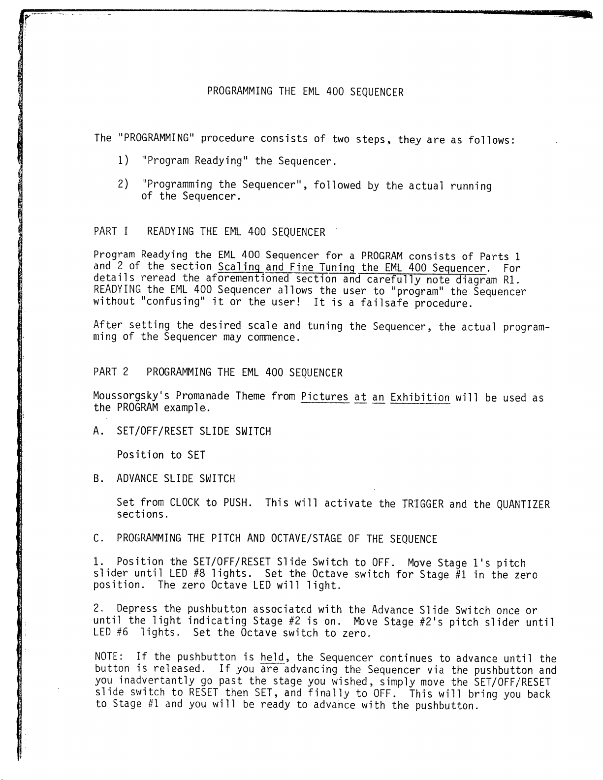
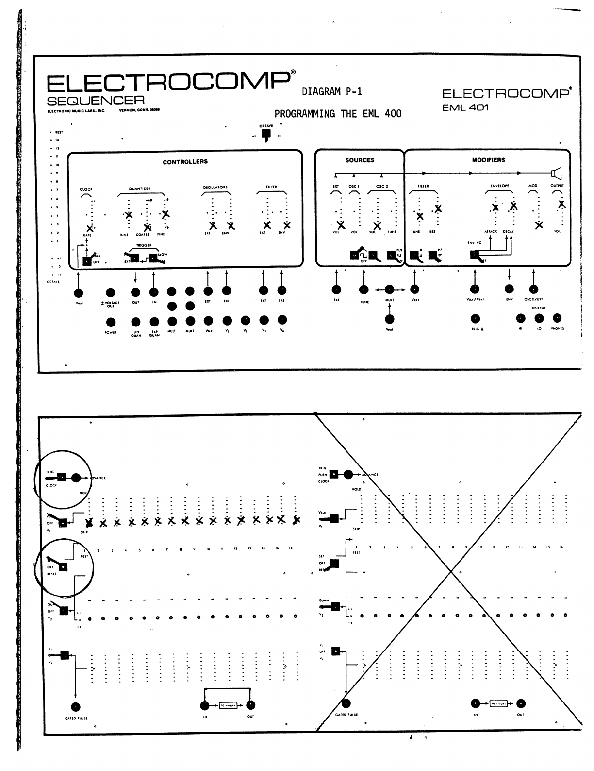
PROGRAMMING
THE
EML
400
SEQUENCER
The
"PROGRAMMING"
procedure
consists
of
two
steps,
they
are
as
follows:
1)
"Program
Readying"
the
Sequencer.
2)
"Programming
the
Sequencer",
followed
by
the
actual
running
of
the
Sequencer.
PART
I
READYING
THE
EML
400
SEQUENCER
Program
Readying
the
EML
400
Sequencer
for
a
PROGRAM
consists
of
Parts
1
and
2
of
the
section
Scaling
and
Fine
Tuning
the
EML
400
Sequencer.
For
details
reread
the
aforementioned
section
and
carefully
note
diagram
Rl.
READYING
the
EML
400
Sequencer
allows
the
user
to
"program"
the
Sequencer
without
"confusing"
it
or
the
user!
It
is
a
failsafe
procedure.
After
setting
the
desired
scale
and
tuning
the
Sequencer,
the
actual
program
ming
of
the
Sequencer may
commence.
PART
2
PROGRAMMING
THE
EML
400
SEQUENCER
Moussorgsky's
Promanade
Theme
from
Pictures
at
cm
Exhibition
will
be
used
as
the
PROGRAM
example.
A.
SET/OFF/RESET
SLIDE
SWITCH
Position
to
SET
B.
ADVANCE
SLIDE
SWITCH
Set
from
CLOCK
to
PUSH.
This
will
activate
the
TRIGGER
and the
QUANTIZER
sections.
C.
PROGRAMMING
THE
PITCH
AND
OCTAVE/STAGE
OF
THE
SEQUENCE
1.
Position
the
SET/OFF/RESET
Slide
Switch
to
OFF.
Move
Stage
l's
pitch
slider
until
LED
#8
lights.
Set
the
Octave
switch
for
Stage
#1
in
the
zero
position.
The
zero
Octave
LED
will
light.
2.
Depress
the
pushbutton
associated
with
the
Advance
Slide
Switch
once
or
until
the
light
indicating
Stage
#2
is
on.
Move
Stage
#2's
pitch
slider
until
LED
#6
lights.
Set
the
Octave
switch
to
zero.
NOTE:
If
the
pushbutton
is
held,
the
Sequencer
continues
to
advance
until
the
button
is
released.
If
you
are
advancing
the
Sequencer
via
the
pushbutton
and
you
inadvertantly
go
past
the
stage
you
wished,
simply
move
the
SET/OFF/RESET
slide
switch
to
RESET
then
SET,
and
finally
to
OFF.
This
will
bring
you
back
to
Stage
#1
and
you
will
be
ready
to
advance
with
the
pushbutton.
Scan by Manual Manor
http://www.markglinsky.com/ManualManor.html
3.
Advance
the
Sequencer
to
Stage
#3.
Position
the
pitch
slider
until
LED#11
lights;
set
the
Octave
switch
to
zero.
4.
Continue
the
process
through
Stage
16
according
to
the
LED
numbers
and
positions
of
the
octave
slide
switches
marked
in
diagram
P-2.
Because
the
theme
is
13
events
long,
the
remaining
3
stages
have
been
set
to
REST
-
no
pitch
is
programmed
or
sounds.
5.
It
is
good
practice
to
go
through
the
sequence
again
just
to
double
check
and
make
sure
all
the
pitches
and
octave
settings
are
correct.
D.
SETTING
THE
DURATIONS
OF
EACH
PITCH/STAGE
IN
THE
SEQUENCE
-
PROGRAMMING
THE
RHYTHMN
-
1.
Diagram
P-3
indicates
the
13
slider
positions
for
the
timing-rhythmn
of
the
sequence.
It
is
ncrt
necessary
to
pushbutton
advance
the
Sequencer
to
set
the
duration
for
each
respective
stage.
The
duration
slide
controls
for
stages
14-16
can
be,
at
your
descretion,
set
to
SKIP
(moving
the
slider
to
the
bottom
of
its
travel)
or
set
to
any
time
increment
up
tp
HOLD
(at
HOLD
the
sequence
will
not
advance
until
the
slider
is
dropped.to
a
definite
time
value).
E.
DEFINING
OVERALL
CHARACTERISTICS
OF
THE
SEQUENCE
1.
The
tempo
of
the
sequence
is
controlled
by
the
CLOCK
slider
control
Vclk
OFF
Switch.
Set
the
CLOCK
slider
next
to
the
third
hash
mark.
2.
SOURCES:
Oscillator
2
may
be
turned
on
to
add
another
voice;
a
waveform
selected,
tuned,
and
its
volume
slider
raised.
The
option
is
open
to
tune
Oscillator
2
to
unison
or
various
intervals
in
relation
to
Oscillator
1
giving
an
effective
chordal
effect.
3.
Octave
transposition
of
the
oscillators
and
filter
is
achieved
with
the
OCTAVE
switch
above
the
CONTROLLER
section.
This
switch
determines
the
overall
range.
4.
FILTER:
The
quality
of
the
sound
is
defined
by
the
Filter.
Experiment
freely
with
the
TUNE
and
RESonance
sliders,
Filter
Select
(HP,
BP,
LP)
and
the
Filter
tracking
(0,
.5,
1)
switches
to
determine
the
timbral
setting
you
wish.
^
5.
ENVELOPE:
The
tenvelope
controls
the
loudness
pattern/pitch/stage.
When
the
envelope
is
in
the
OFF
position,
the
ATTACK
and
DECAY
sliders
determine
the
time
for
their
respective
functions.
Moving
the
switch
to
either
the
Voltage
Control
of
Envelope
Decay
or
Voltage
Control
of
Envelope
Attack
and
Decay,
means
that
the
envelope
no
longer
defines
a
time
unit
for
ATTACK
and
DECAY,
but
rather
the
voltage
controlled
function
now
"reads
time"
or
"reads
voltage".
The
ATTACK
and
DECAY
sliders
now
determine
proportion,
txpenment
Scan by Manual Manor
http://www.markglinsky.com/ManualManor.html

with
the
VOLTAGE
CONTROLLED
ENVELOPE.
It's
a
unique
and
vitalizing
new
synthesizer
function/feature.
6.
MODULATOR:
Ring or
Amplitude
Modulation
can
be
added
to
the
signal(s)
out
of
the
filter.
F.
RUNNING
THE
SEQUENCER
1.
SET/OFF/RESET
SLIDE
SWITCH
Position
in
RESET
2.
THE
ADVANCE
SLIDE
SWITCH
TRIG/PUSH/CLOCK
switch
should
be set
to
CLOCK.
3.
To
"run"
the
sequence
simply
move
the
SET/OFF/RESET
slide
switch
to
SET
and
then
to
OFF.
4.
To
have
the
Sequencer
repeat
be
sure
there's
a
patch
cord
between
the
IN
and
OUT
jacks
near
the
bottom
of
the
PROGRAM
panel.
G.
DIAGRAM
P-5
Patch
5
diagrams
some
special
effects
that
can
be
achieved
with
the
EML
400
Sequencer
and
the
EML 401
module.
For
example,
V3
or_
V4
can
be
used
to
change
the
timbre
of
each
stage;
or
voltage
control
the
envelope
to
vary
the
attack
and/or
decay;
or V3
or
V4
can
be
used
as
a
modulating
signal
and
vary
the
dynamics
of
the
piece.
Many
uses
are
possible.
Scan by Manual Manor
http://www.markglinsky.com/ManualManor.html

ELECTROCOMP*
SEQUENCER
ELECTRONIC
MUSIC
LABS
.
'NC.
VMNON.
COM*.
o
DIAGRAM
R-l
READYING
the EML
400
SEQUENCER
ELECTROCOMP
EML
<4O1
OCTAVt
i
.
u..u
a
SOURCES
I
1
1
txr
osc
1
osc
?
VOt
VOl
tUNI
MOOIFIERS
OltAt
it
i
<i
INV
OSC2/E<I
OUIPUI
IO
*<ONt
S
9
:C
II
s
'X
7
9 9
y
Scan by Manual Manor
http://www.markglinsky.com/ManualManor.html
ELECTROCOMP
SEQUENCER
CLECTRONIC
MUSIC
LABS..
INC.
Vf
ANON.
CONN.
MOM
DIAGRAM
P-l
PROGRAMMING
THE
EML
400
ELECTROCOMP*
EML
1
-....•♦
ii
QU
UN
W
QUAN
QUAN
*«UIT
Vui
V,
V2
V3
V«
SOURCES
EXT
OSCI
OSC
7
voi voi voi
MODIFIERS
■k*
CNvElOfC
MOO
OUTPUT
ATTACK
DECAY
MUIT
Veil
y
o
'
i i
i
tO
'HONES
(
(
>BJ-)i
f^
12
I)
U
IS 16
•-E3-4
I
t
Scan by Manual Manor
http://www.markglinsky.com/ManualManor.html
ELECTROCOMP*DIAGRAM
p-2
PROGRAMMING
THE
EML
400
SEQUENCER
ELICTHON1C
«U««
LAO*.
INC.
VBKNON.
CONN.
O0OM
a..ii
£XT
!XT
EXT
EXT
ELECTROCOMP
EML
4O1
SOURCES
x
1^
1^—
EXT
OSC
1
OSC
2
■E
MODIFIERS
**
ENVELOTC
MOO
OUTPUT
ATTACK
DECAY
i"i-^i'
'i
i i
MUIT
Va«l
ENV
OSC
1
/EXT
IO
PHONES
10
11
13
«,».
I
1
-
I i
Scan by Manual Manor
http://www.markglinsky.com/ManualManor.html

I
ELECTROCOMP*
DIAGRAM
P-3
SEQUENCER
MUSIC
LAM.
me.
VMMON.COMN.M
V«al
♦YOUAOI
OUT
IN
PROGRAMMING
THE
EML
400
11
ELECTROCDMP
EML
<4O1
SOURCES
EXT
OSCI
OSC
2
j
X
: :
v;
:
V
:
vot^
voi
yft^
TUN!
MULT
V»«l
.
MODIFIERS
MOO
OUTPUT
[TACK
DtCAY
Ul
Vai/V»t
£NV
OSC2/EKT
OUTPUT
Scan by Manual Manor
http://www.markglinsky.com/ManualManor.html
1.
CLOCK
The
CLOCK
slide
control
effects
the
Wmpo
of
the
sequence.
The
Vclk/OFF
switch
determines
whether
the
CLOCK
rate
is
controlled
by the
Vclk
voltage
from
a
PROGRAM
PANEL.
In
OFF,
the
sequence
will
advance
at
a
constant
tempo
controlled only
by
the
Clock's
Slide
Control,
it
ignores
the
voltages
set
by
the
first
row
sliders.
An
external
control
voltage
from
an
appropriate
source
may
be
patched
into
Vext
to
further
control
the
tempo
of
a
sequence.
2.
QUANTIZER
The
TUNE
control
is
used
to
transpose
the
pitch
produced
by
the
QUANTIZER
output
voltage.
The
COARSE
and
FINE
controls
are
used
to
adjust
the
tuning
interval.
;
3.
The
QUANTIZER
voltage
is
applied
to
the
Light
Emitting
Diodes.
The
lights,
numbered
1-13
(vertical
column
of
lights,
left
of
the
CONTROLLER
PANEL)
corres
pond
to
an
octave
and
one note
on the
12
tone
scale.
The
TUNE
control
may
be
used
to
transpose
pitch
so
that
the
#1
light
corresponds
to
a
particular
pitch,,
such
as
a
C.
If
the
interval
controls
are
adjusted
for
the
12
tone
scale,
light
2
will
correspond
to
C#,
light
3
to
D,
etc.
Light
13
will
be
a
C,
up
one
octave
from
light
1.
The
green light
indicates
the
active
stage
is
in
REST.
No
pitch
has
been
set,
nor
will
a
pitch
sound.
The
-1,
0,
+1
lights
indicate
the
octave
setting
of
the
active
sequencer
stage.
In
tuning
the
instrument
to
the
proper
interval,
note
that
in
the
-1
octave,
light
1
condition,
the
COARSE
and
FINE
Quantizer
controls
have
no
effect.
This
provides
a
convenient
reference
point.
It
is
necessary
to
set the instru
ment
to
this
condition
and
adjust
the
pitch
to
a C
or
any
other
convenient
pitch
with
the
QUANTIZER
TUNE
control,
then
go
to
a
+1
octave,
light
13
condi
tion
and
use the
FINE
control
to
adjust
the
pitch
to
precisely
3
octaves
above
the
previous
pitch.
The
COARSE
control
is
used
for
generating microtonal
scales.
(See
the
section
on
Scaling
and
Fine
Tuning
the
EML
400
Sequencer.)
4.
TRIGGER
The
TRIGGER
section
performs
a
variety
of
functions.
It
consists
of two
switches
and
two
jacks.
The
TRIGGER
OUT
jack provides
a
pulse
which
may
be
used
to
trigger
the EML
101,
200
or
500.
The
output
of
the
INTERNAL/EXTERNAL
slide
switch
is
routed
to
the
envelope
of
the
401
module.
In
INTERNAL
position,
a
trigger
pulse
will
be
directed
to
the
envelope
at
each
clock
advance
except
for
rests
and
skips
In
the
EXTERNA!
position,
pulses
inputted
at
the
TRIGGER
IN
jack
will
be
directed
to
the
envelope,
and
will
cause
the
sequence
to
advance
if
the
PROGRAM
PANEL
Advance
Switch
is
in
the
TRIGGER
position.
The
TRIGGER
Input
Switch
will
normally
be
in
the
FAST
position
unless
a
"noisy"
source
such
as
the
EML
100/101
Gate1
Out
signal
is
used
to
advance
the
sequence.
Scan by Manual Manor
http://www.markglinsky.com/ManualManor.html

5.
OSCILLATORS
This
is
an
OSCILLATOR
CONTROL
MIXER
used
to
provide
vibrato
and
transposition
voltages
to
the
Oscillators.
The
two
jacks
labeled
EXT
are
used
to
bring
external
control
voltages
to
the
Oscillators.
The
slide
control
labeled
ENV
norma-ly
has
envelope
voltage
applied
to
it
unless
an
external
voltage
is
patched
in
at
the
EXT
jack
immediately
below
it.
6.
FILTER
This
is
a
FILTER
CONTROL
MIXER
used
to
provide
additional
timbre
control
volt
ages
to
the
Filter.
The
two
jacks
labeled
EXT
are
used
to
bring
external
control
voltages
to
the
Filter.
The
slide
control
labeled
ENV
normally
has
envelope
voltage
applied
to
it
unless
another
voltage
is
patched
in
at
the
EXT
jack
immediately
below
it.
7.
OCTAVE
SWITCH
The
Octave Switch
transposes
the
pitch
set
at
the
active
stage
by
two
octaves.
Both
Oscillators
and the
Filter
are transposed.
8.
EXPAND
OUT
CONNECTOR
The
cable
provided
should
be
connected
between
this
connector
and
one
on
the
PROGRAM
PANEL.
9.
LINEAR
QUANTIZE
JACK
Provides
pitch
voltage
output
to
the
SEQUENCER
INput
on
the
EML
101
and
500.
All
EML
100's
and
early
serial
numbered
EML
101's
may
require
minor
modification.
See the
back
of
the
manual.
On
the
EML
101"s
with
serial
numbers
646
or
above,
the
CM3
jack
has
been
modified
to
accept
the
SEQUENCER.
INPUT.
I
10.
EXPONENTIAL
QUANTIZE
JACK
Provides
pitch
voltage
output
to
EML
200
Voltage
Control
Oscillators.
11.
MULTIPLE
Two
3
jack
multiples
are
provided.
12-
Vclk
VI
V2
These
Voltages appear
at
jacks
for
further
use
as
determined
by
the
positions
of
the
various
voltage
V3
routing
switches
on
a
PROGRAM
PANEL.
V4
Scan by Manual Manor
http://www.markglinsky.com/ManualManor.html
PART
II
SCALING
AND
FINE
TUNING
THE
EML
400
SEQUENCER
A.
QUANTIZER
Part
1
Set
the
COARSE
slider
so
it
corresponds
to
12.
12
represents
12
tones/octave,
the
semitone
scale.
The
various
scales
set
by
the
COARSE
control
span
12
tones/octave
up
to
60
tones/octave.
Temporarily
place
the
FINE
control
slider
in
the
middle
of
its
travel.
Fine
tuning
the
sequencer
to
a
reference
is
realized
utilizing
the
FINE
slide
control
-
the
procedure
for
this
is
detailed
in
QUANTIZER
PART
2.
B.
SET/OFF/RESET
SLIDER
SWITCH
1.
Move
this
switch
from
the
RESET
position
to
the
SET
position.
When
this
switch
is
in
the
RESET
position,
LED
#1
should
be
on.
(The
vertical
column
of
QUANTIZER
LED'S
juct
left
of
the
CONTROLLERS
section.) Switching
to
SET,
an
LED
numbered
1-13,
or
the
RECT
LED
(the
green
LED)
will
appear.
This
is
completely
dependent
on
the
position
of
the
slider
in
Control
Voltage
Row
#2
of
Stage
#1.
In
addition,
an
Octave
light
will
light,
depending
on
which
position
Stage
l's
Octave
Switch
is in.
2.
The
first slide
of
Control
Voltage
Row
#2
(Stage
#1)
should
be
moved
all
the
way
to
the
bottom
of
its
travel
until
LED
#1
lights.
The
Octave
switch
associated
with
Stage
1
positioned
to
-1.
The
corresponding
LED
will
appear.
C.
QUANTIZER
Part
2
1.
Using
the
TUNE
slider
in
the
QUANTIZER
section
tune
the
sequencer
to
the
pitch
(frequency!
of
your
reference
(or
as
you
desire).
Adjust
the
TUNE
slider
until
they
no
longer
"beat".
2.
Increase
the
pitch
of the
reference
source_
by
two
octaves
(or
triple
frequency).
Now
shift
the
Octave
switch
associated
with
Stage
1
to
the
+1
position.
Use
the
H_NE
slide
control
to
tune
the
two
pitches
until
the
"beating"
ceases.
The
Sequencer
is
now
tuned
and
octavated!
It
is
ready
to
PROGRAM!
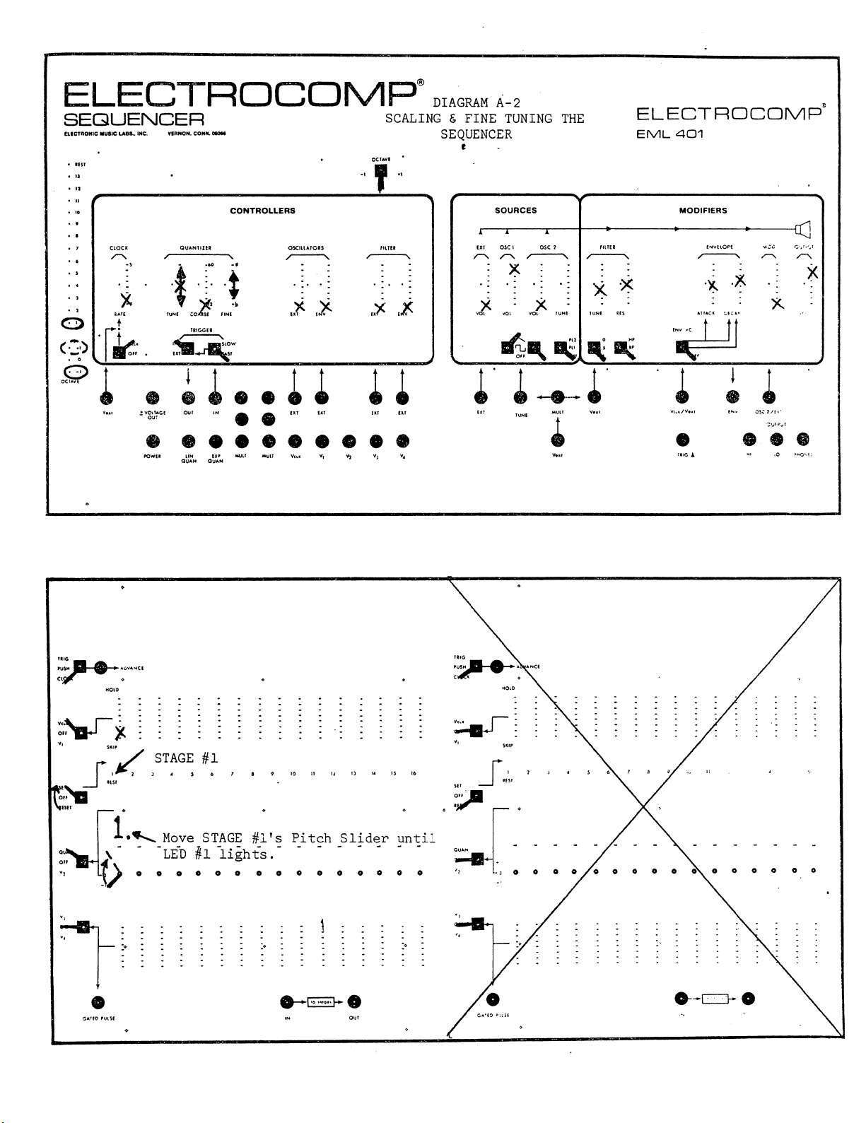
NOTE Diagrams
A-l
and
A-2
Scan by Manual Manor
http://www.markglinsky.com/ManualManor.html
This manual suits for next models
2
Table of contents


