Northern Fridge TruckFridge TF49 User manual
TruckFridge Built-in User Manual
Updated 5 July 2020 Page 1
By
Model TF49
Model TFDR49
Model TF65
Model TF130

TruckFridge Built-in User Manual
Updated 5 July 2020 Page 2
TABLE OF CONTENTS
1.0
GENERAL INFORMATION
4
1.1
Introduction
4
1.2
Notice
4-5
2.0
COMPONENTS
5
2.1
Components/Refrigeration System Illustrations
5
2.1.1
Compressor
5
2.1.2
Electronic Control Unit (ECU)
6
2.1.2.1
Replacing the ECU
6
2.1.3
Condenser
7
2.1.4
Evaporator
7
2.1.5
Thermostat
7
2.1.6
Fan
7
2.1.7
Dehydration Filter (Dryer)
7
3.0
INSTALLATION
7-8
3.1
Installing the TF49 in Freightliner Cascadia
8
3.1.1
Installing replacement TF49 with TF49-2PCAS-R Installation Kit
8-9
3.1.2
Installing new TF49 with TF49-4PCAS-N Installation Kit
10-11
3.2
Ventillation
12
3.3
Wiring System: Function and Features
12
3.3.1
Wiring Connections
12-13
3.4
Replacing the Door Panel
13
3.5
Reversing the Door Opening
14
4.0
FEATURES
14
4.1
Setting the Inside Temperature
14
4.2
Filling
14
4.3
Defrosting
15
5.0
MAINTENANCE
15
5.1
Useful Advice
15
6.0
TROUBLESHOOTING
16
6.1
Troubleshooting Guide
16
6.2
Self-Diagnostics
16-17
6.3
Thermostat Test
17
7.0
SPECIFICATIONS
18
7.1
TruckFridge Model TF49
18
7.2
TruckFridge Model TFDR49
18
7.3
TruckFridge Model TF65
19
7.4
TruckFridge Model TF130
19
8.0
ILLUSTRATIONS
20
8.1
TF49 Fridge Parts Diagram
20
8.1.1
TF49 Fridge Parts List/Description
21
8.1.2
TF49 Cooling System Parts Diagram
22
8.1.3
TF49 Cooling System Parts List/Description
23
8.2
TFDR49 Fridge Parts Diagram
24

TruckFridge Built-in User Manual
Updated 5 July 2020 Page 3
8.2.1
TFDR49 Fridge Parts List/Description
25
8.2.2
TFDR49 Cooling System Parts Diagram
26
8.2.3
TFDR49 Cooling System Parts List/Description
27
8.3
TF65 Fridge Parts Diagram
28
8.3.1
TF65 Fridge Parts List/Description
29
8.3.2
TF65 Cooling System Parts Diagram
30
8.3.3
TF65 Cooling System Parts List/Description
31
8.4
TF130 Fridge Parts Diagram
32
8.4.1
TF130 Fridge Parts List/Description
33
8.4.2
TF130Cooling System Parts Diagram
34
8.4.3
TF130 Cooling System Parts List/Description
35
8.5
Danfoss/Secop BD35F-HD Compressor Specifications
36-37
8.6
TruckFridge 101N0212 ECU 12VDC Specifications for BD35F-HD
38
8.6.1
TruckFridge 101N0212 ECU 12VDC Wiring Diagram
39
8.7
TruckFridge 101N0500 ECU 12VDC, 110VAC Specifications
40
8.7.1
TruckFridge 101N0500 ECU 12VDC, 110VAC Wiring Diagram
41
8.8
TF49 Dimensional Diagram
42
8.9
TFDR49 Dimensional Diagram
43
8.10
TF65 Dimensional Diagram
44
8.11
TF130 Dimensional Diagram
45
8.12
TruckFridge Installation Ventilation Diagram
46

TruckFridge Built-in User Manual
Updated 5 July 2020 Page 4
1.0 GENERAL INFORMATION
1.1 Introduction
The TruckFridge Built-in refrigerator (TruckFridge) has been designed and tested to give many years of performance and
reliability. The 12 and 24 Vdc power supply (110-220 Vac optional) makes them especially versatile. The power source can
either be a battery, a transformer, a photo-voltaic (Solar) panel or common household 110Vac. Provided with a totally
watertight compressor, they offer a minimal power consumption and noise level. All the models are extremely easy to install.
They can work even if they are assembled at a slant of up to 30°. In order to make sure that your TruckFridge refrigerator
works as efficiently as possible, please pay attention to the following general instructions:
•Never connect a battery charger directly to the refrigerator. A battery and in-line 15 amp fuse must be used to
protect the compressor and Electronic Control Unit (ECU).
•Reduce opening the door of the refrigerator to reduce the waste of energy
•Proper ventilation of the compressor and of the condenser unit reduces the energy consumption and increases
overall efficiency and performance.
•The wiring system of the vehicle is in proper condition. Routinely check the batteries and the charge level. Follow the
instructions about the cable cross sections and the fuse connections strictly. See Section 3.5: Wiring System:
Function and Features for details.
•Keep the inside of the refrigerator clean and dry. Remove any condensate water which might gather in the tray
under the freezer compartment
•Keep the door of the refrigerator slightly open in order to air it out if you do not use it for a long time, for example in
winter.
1.2 Notice
WARNING! Do not install the refrigerator near heat sources.
WARNING! Keep ventilation openings in the appliance enclosure or in the built-in structure, clear of obstruction.
WARNING! Do not use mechanical devices or other means to accelerate the defrosting process, other than those
recommended by the manufacturer.
WARNING! Do not damage the refrigerant circuit during handling.
WARNING! Do not use electrical appliances inside the food storage compartments of the appliance, unless they are
of the type recommended by the manufacturer.
WARNING! Do not store explosive substances such as aerosol cans with a flammable propellant in this appliance.
WARNING! Risk of fire and electrical shock or fire.
WARNING! Do not let hot items to touch the plastic parts of the appliance.
WARNING! Do not store flammable gas and liquid in the appliance.
WARNING! Do not put flammable products or items that are wet with flammable products in, near or on the
appliance.
WARNING! Do not touch the compressor or the condenser. They may be hot.

TruckFridge Built-in User Manual
Updated 5 July 2020 Page 5
WARNING!
• The refrigerator is suitable for the preservation and/or storage of food items and maintaining already
frozen food.
• Use the fridge exclusively for cooling and storing closed beverages and snacks.
• Food may only be stored in its original packaging or in suitable containers.
• The fridge is not intended to be brought into contact with food.
• The fridge is not intended for the proper storage of medicines. See the instructions in the package leaflet for the
medicinal product.
2.0 COMPONENTS
2.1 Components/Refrigeration System Illustrations
Model TF49
See 8.1 TF49 Fridge Parts Diagram.
See 8.1.1 TF49 Fridge Parts List/Description.
See 8.1.2 TF49 Cooling System Parts Diagram.
See 8.1.3 TF49 Cooling System Parts List/Description.
Model TFDR49
See 8.2 TFDR49 Fridge Parts Diagram.
See 8.2.1 TFDR49 Fridge Parts List/Description.
See 8.2.2 TFDR49 Cooling System Parts Diagram.
See 8.2.3 TFDR49 Cooling System Parts List/Description.
Model TF65
See 8.3 TF65 Fridge Parts Diagram.
See 8.3.1 TF65 Fridge Parts List/Description.
See 8.3.2 TF65 Cooling System Parts Diagram.
See 8.3.3 TF65 Cooling System Parts List/Description.
Model TF130
See 8.4 TF130 Fridge Parts Diagram.
See 8.4.1 TF130 Fridge Parts List/Description.
See 8.4.2 TF130 Cooling System Parts Diagram.
See 8.4.3 TF130 Cooling System Parts List/Description.
2.1.1 Compressor
The TruckFridge refrigerator uses the Direct Current Danfoss/Secop BD35F-HD compressor that is specially designed
for extraordinary performance at minimum power consumption, superbly silent-running and reliable operation even
when tilted up to 30 degrees.
HD (Heavy Duty) version of the BD35F which can handle extreme vibrations.
TruckFridge Built-in User Manual
Updated 5 July 2020 Page 6
2.1.2 Electronic Control Unit (ECU)
The Electronic control unit of the compressor is a piece of electronic equipment which carries out all the controls
and electrical protection of the compressor system. Its main features include;
a) Protection of the battery with automatic turning off of the compressor when the feeding voltage reaches the
minimum threshold (cut out) typically 10 volts. The compressor will start up automatically again when the voltage
goes back to normal values (cut in). Typically 11 volts. Must always be directly connected to the battery.
b.) Thermal overload protection cut out. The compressor will shut down when temperatures exceed 125 deg F
ambient to protect the compressor from overheating. It will cut in automatically when temperatures drop below
this.
c.) Cooling fan operation will begin automatically when compressor starts and stop when compressor shuts off in
normal operation.
The main functions of the 101N0212 is to provide all controls for the BD35F-HD compressor systems including:
• Supports both 12VDC (max. 17VDC) and 24VDC (max. 31.5VDC)
• Maximum ambient temperature is 55OC with built-in thermal protection
• Motor / Compressor speed control
• Thermostat control (ON / OFF)
• Condenser fan control including speed setting
• Error codes
• Battery protection functions. Polarity inversion protection.
See 8.6.1 TruckFridge 101N0212 ECU 12VDC Specifications for BD35F-HD.
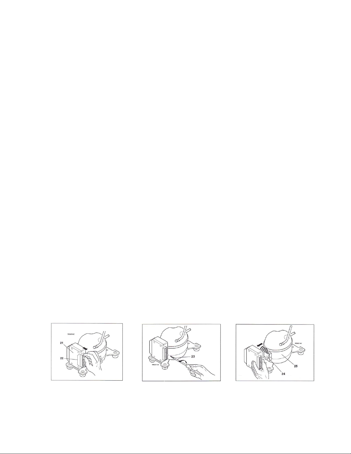
2.1.2.1 Replacing the ECU
The ECU can be simply removed and/or installed by removing a screw to release module for the side of the
compressor to reveal the 3-pin plug that attaches the ECU to the compressor. Follow these simple steps;
1. Disconnect all terminals (22) from the control ECU and, while doing so, mark them adequately, so as not to
connect them wrongly during reassembly. See Figure 2.1.2.1.1
2. Unscrew the screw (23). See Figure 2.1.2.1.2.
3. Disconnect the connector (24) from the ECU, from the compressor (25). See Figure 2.1.2.1.3
4. Replace the damaged ECU by first assembling the left hand side and afterwards press the right hand side on the
screw head on the bracket. ln this way the ECU gets locked on the bracket and is securely fastened to the
compressor.
Figure 2.1.2.1.1
Figure 2.1.2.1.2
Figure 2.1.2.1.3
TruckFridge Built-in User Manual
Updated 5 July 2020 Page 7
2.1.3 Condenser
The condenser may be of static or ventilated type. Since its function is to dissipate heat, it must be placed in a zone
allowing for the maximum heat exchange with the environment and must not be clogged with dust or other
substances preventing the exchange of heat. See 8.12 TruckFridge Installation Ventilation.
2.1.4 Evaporator
The evaporator is the element where the gas is expanded causing heat absorption thereby cooling the ambient air
around it. The capillary pipe is an integral part of the evaporator that creates a narrow path for the gas causing a
pressure difference between the circuit delivery and suction. If the capillary pipe gets obstructed, the entire
evaporator must be replaced.
2.1.5 Thermostat
The TruckFridge is provided with a manual thermostat located inside the refrigerator on
the upper right side next to the freezer. Turn the knob clockwise to lower (1) the
temperature and turn counter-clockwise to raise (7) the temperature and activate the
ON-OFF switch in its end (0) position.
In case of anomalies or fault, the thermostat cannot be repaired and
must be replaced. See Figure 2.1.5.1: TruckFridge Thermostat
2.1.6 Fan
The electronic type fan, with brushless motor, for an almost unlimited lifespan. The fan is connected between the
ECU (+) and “F” terminals. A 12VDC fan is always used for both 12VDC and 24VDC power sources. In case of damage,
the fan must always be entirely replaced.
2.1.7 Dehydration Filter (Dryer)
The dryer has the double task of blocking any solid impurity through a metal mesh and of absorbing any possible
humidity (moisture) present in the fluid by means of a highly hygroscopic molecular sieve. Always replace the sieve
every time the circuit is opened for repair.
3.0 INSTALLATION
The refrigerators from TruckFridge are assembled to be installed in a standard factory cabinet. In some cases, if the
truck was not equipped with a fridge from the truck factory, the cabinet may be slightly different and require a slight
modification to install a fridge. Note any additional instructions included with the packing list when purchasing the
fridge new. The fridge weight must always be sitting on its feet to support the weight. In some cases, a block may be
needed under the bottom of the fridge to lift it off the floor of some cabinets to fill in gaps at the top. This allows air
to enter the cabinet from the bottom. In other cases, a filler strip may be needed to make up gaps in the side of
some truck cabinets that were not originally designed for fridge.
See the following dimensional diagrams listed below for further details.
See 8.8 “TF49 Dimensional Diagram”for details.
See 8.9 “TFDR49 Dimensional Diagram”for details.
See 8.10 “TF65 Dimensional Diagram”for details.
See 8.11 “TF130 Dimensional Diagram”for details.
Figure 2.1.5.1: TruckFridge Thermostat

TruckFridge Built-in User Manual
Updated 5 July 2020 Page 8
Most models from TruckFridge can be installed by attaching the applicable fridges installation kit(s) to the truck
cabinet using the appropriate screws required for the material of the truck cabinet.
It is very important for the refrigerating unit, consisting of the compressor and the condenser, to be well ventilated,
with the cool air typically coming in from the bottom and going out from the top. You must ensure proper
ventilation of the refrigerating unit. The air inlets and outlets must have a free cross section of at least 10 square
inches total. See 8.12 TruckFridge Installation Ventilation Diagram for details.
Take great care when handling the fridge and avoid handling the refrigeration tubes in order to prevent breakages.
The compressor must normally stand in a vertical position.
3.1 Installing the TruckFridge Model TF49 in Freightliner Cascadia.
3.1.1 Installing a replacement Model TF49 with TF49-2PCAS-R Installation Kit
The TF49-2PCAS-R 2 piece Freightliner Cascadia replacement installation kit is used to replace an OEM refrigerator in
a Freightliner Cascadia that previously had a factory installed refrigerator (black steel mounting plates are still
mounted in the bottom of the truck cabinet). The TF49-2PCAS-R installation kit must be installed on the bottom of
the TF49, then simply slide in the new refrigerator on the existing floor bracket, bolt it into place and the new
refrigerator is installed.
Remember. This is ONLY for Freightliner Cascadia that already has the factory fridge black bottom mounting plate
and top bracket already in the cabinet. If your Freightliner Cascadia cabinet does not have the factory bottom black
mounting plate inside the cabinet, you will need to order the complete TF49-4PCAS-N installation kit.
Remove the 3 sided trim flange from the fridge and discard. Reinstall the screws into the original holes.
The galvanized plate and top "L" brackets included in the kit must be attached to the bottom and top of the TF49 as
described below.
Carefully turn the fridge upside down and set it on top of the Styrofoam shipping lid. Align the bottom bracket 1/2"
from front of fridge cabinet, not the door, and centered side to side. (If silicone caulking is available, apply a small
amount to each screw hole in bracket to minimize potential of screws loosening.) Install bracket using 3/4" long #10
sheet metal screws. See Figure 3.3.1.1: Attaching bracket to bottom of fridge.
WARNING !
•Insure thermostat is turned off inside the fridge before continuing.
•Insure fridge has been sitting upright for a minimum of 4 hours before turning on ! Failure to do so
may destroy compressor and void warranty!
•
WARNING !!
DO NOT POWER ON THE FRIDGE FOR A MINIMUM OF 4 HOURS AFTER INSTALLATION.
The compressor must normally stand in a vertical position. During shipping, the fridge may be turned on its
side or upside down. This may cause the compressor oil to drain from the compressor into the capillary pipe
thereby obstructing operation of the evaporator. You must allow time for the oil to drain back into the
compressor for proper lubrication. FAILURE TO DO THIS MAY DAMAGE THE COMPRESSOR AND/OR
EVAPORATOR AND VOID YOUR WARRANTY.
TruckFridge Built-in User Manual
Updated 5 July 2020 Page 9
Figure 3.3.1.1: Attaching bottom bracket to bottom of fridge
Turn fridge right side up and center top bracket 1/2" from front of fridge cabinet, centered side to side. (If silicone
caulking available, apply a small amount to each screw hole in bracket to minimize potential of screws loosening.)
Install bracket using 3/4" long #10 sheet metal screws. It may be necessary to predrill the 2 front holes due to the steel
latch plate on the fridge. See Figure 3.3.1.2: Attaching top bracket to top of fridge
Figure 3.3.1.2: Attaching top bracket to top of fridge
Once installed, simply slide in the new refrigerator on the existing black “bottom” floor bracket, bolt it into place and
the new refrigerator is installed. Final appearance is just like the OEM at a fraction of the price.
Note. If black “bottom” bracket is not installed in the cabinet you will need to install using the TF49-4PCAS-N
Installation Kit as described in “3.3.2: Installing a new refrigerator with the TF49-4PCAS-N Installation Kit” below.
TruckFridge Built-in User Manual
Updated 5 July 2020 Page 10
3.1.2 Installing a new Model TF49 with TF49-4PCAS-N Installation Kit
The TF49-4PCAS-N is a 4 piece Freightliner Cascadia Installation Kit required for installing the TF49 in Freightliner
Cascadia cabinets that did not originally have a factory refrigerator installed. (Note. The TF49-4PCAS-N installation
kit includes the TF49-2PCAS-R installation Kit).
Install and bolt in place the black “bottom” mounting plate to the floor of the cabinet using existing holes in cabinet.
No drilling required. Refrigerator plugs into existing factory wiring harness from the REAR of lower cigarette type
plug. (NEVER USE A CIGARETTE PLUG AS A PERMANANENT CONNECTION.)
Next, install the TF49-2PCAS-R Installation Kit to the “bottom” of the TruckFridge TF49 as described in “3.3.1:
Installing a replacement refrigerator with the TF49-2PCAS-R Installation Kit” above.
Installation time is also faster and typically takes about 1/2 hour for an average person. This kit contains all the
hardware needed. Requires basic hand wrench and socket and possibly a drill. NOTE: If your cabinet has a door, this
will need to be removed. Freightliner does sell a trim bezel for this cabinet when a fridge is installed. Freightliner
Cascadia Fasica fridge cabinet trim frame without wood grain (#A18-62503-002).
Note: Some trucks vary depending on specification at time of manufacture. TruckFridge assumes no responsibility or
liability as a result of variations on trucks specs.
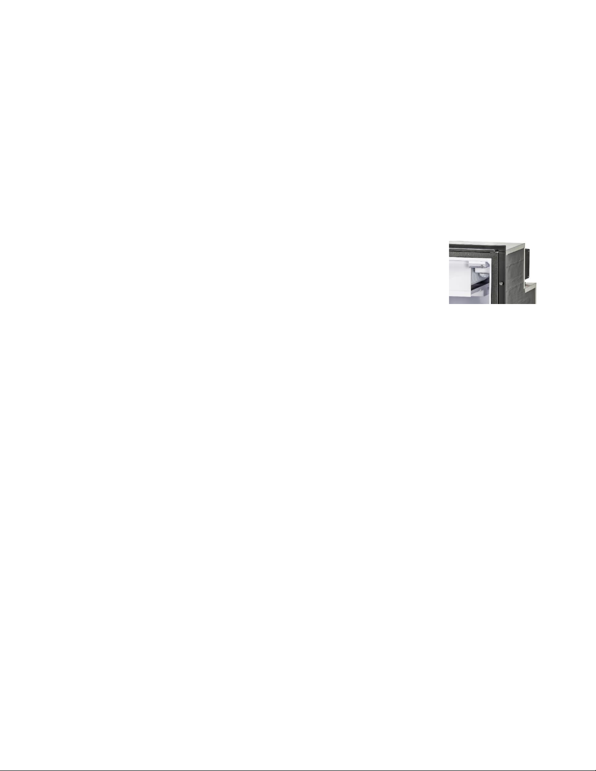
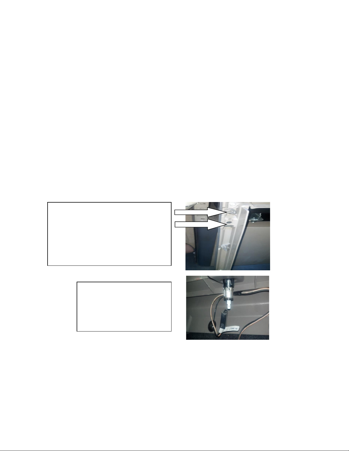
Removing the trim frame on the truck cabinet:
Some models may be held in place with 4 screws
from the back side. In this case, remove the clip
nuts from the trim frame. These will need to be
replaced with included plastic “trees” as screws
cannot be reinstalled once the fridge is mounted.
Some frames are held in place with push clips.
These can be reused.
If your vehicle came without a
factory installed fridge, locate 12v
accessory power point plug at rear
of shelf. Reach underneath to unlock
and push power plug and wire up
through hole in shelf.
TruckFridge Built-in User Manual
Updated 5 July 2020 Page 11
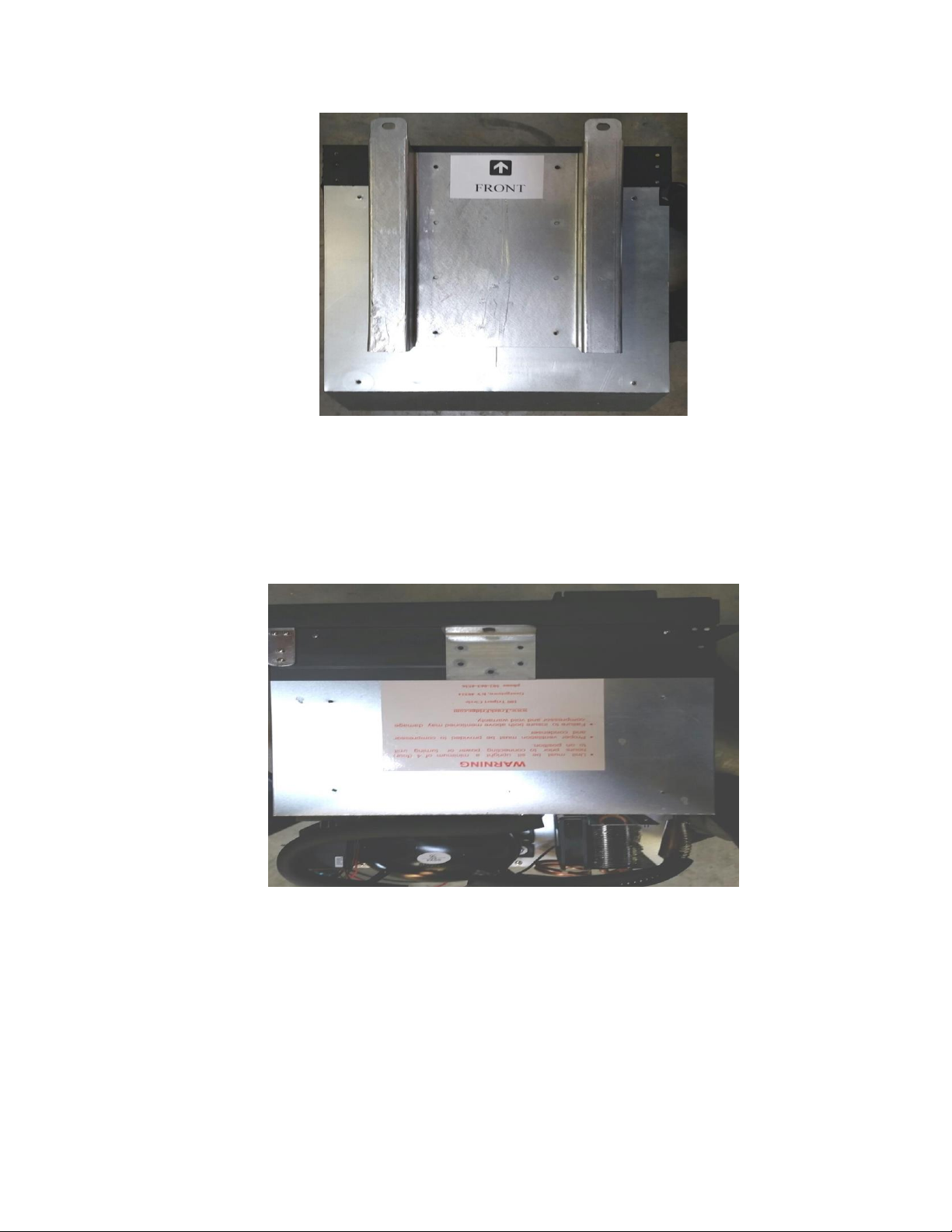
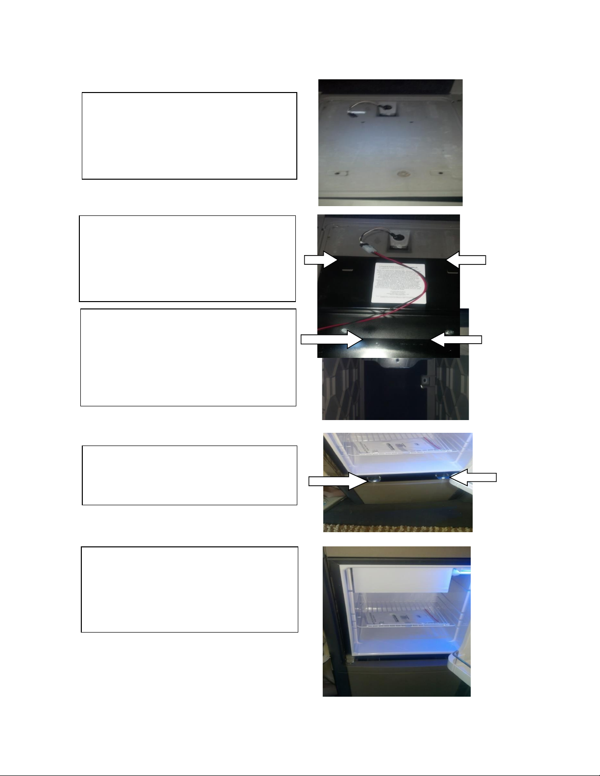
Align large black mounting plate with existing
holes already in cabinet platform. They can be
located from bottom, if shelf is covered with
carpet, poke up through holes and through the
carpet. (Carpet removed in picture for
demonstration purpose only.)
Bolt mounting plate to bottom of cabinet with
finger tabs along the back of the cabinet, pointed
up and toward center of truck. Check to be sure
fridge thermostat is turned off in case unit has
been tilted during installation. Connect the fridge
power plug to the truck power cord plug.
If your cabinet does not have a top mount
bracket, use small black TF top bracket with black
push clips and secure to bracket in the top of
cabinet. This will bolt to TF top fridge bracket. If
your truck already has top mounting bracket as
shown here, the TF top bracket and push clips will
not be needed.
Slide fridge on to mounting plate, aligning rear
finger tabs to fridge bottom plate. Insure wires
are not pinched or rubbing. Align front holes and
secure with included bolts and lock nuts.
Install cabinet trim frame using plastic “trees” as
mentioned previously. Fridge light will be on
when door is open even when thermostat is in “0”
Off position. Do not turn fridge on until it has
remained in upright position at least 4 hours prior
to being installed.
TruckFridge Built-in User Manual
Updated 5 July 2020 Page 12
3.2 Ventilation
It is very important for the refrigerating unit, consisting of the compressor and the condenser to be well ventilated
with adequate air flow into and out of the cabinet housing the refrigerator. See 8.12 TruckFridge Installation
Ventilation Diagram for details. Do not install the refrigerator near heat sources
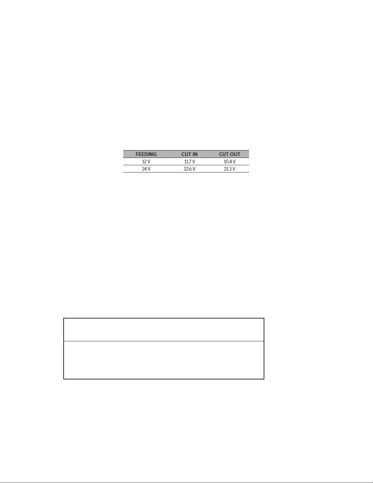
3.3 Wiring System: Function and Features
The Electronic Control Unit (ECU) is a piece of electronic equipment which controls the motor of the compressor and
carries out all the controls and electrical protection of the system. The ECM provides protection of the battery with
automatic turning off of the compressor when the feeding voltage reaches the minimum threshold level (cut out).
The compressor will start up automatically again when the voltage goes back to normal values (cut in). See Table
3.5.1: ECM Cut-Out / Cut-In Voltages.
Table 3.5.1: ECU Cut-Out / Cut-In Voltages
3.3.1 Wiring Connections
Typically, your TruckFridge will have the correct gauge wire and connector installed on the fridge to connect to the
standard truck factory wiring. If the truck was not equipped with a fridge from the factory, the manufacturer would
often connect the fridge wire to a 12v cigarette type receptacle. In these cases, unplug the connector from the rear
of this receptacle and plug this into the connector on the fridge wires. NOTE: There are proper wire connectors
available from TruckFridge for most truck wiring installations.
When you connect the refrigerator, you must remember the following:
1) Use cables having the proper cross section to make the feeding lines. If possible, such cables should be without
any joints on the leads which could lead to voltage falls. See “Table 3.5.1.1: 12VDC Wire Gauge Chart”below.
2) If the wiring system of the vehicle is insufficient or not properly sized for the refrigerator, we suggest you
connect it directly to the battery. Note. The use of cables having an insufficient cross section may lead to the
compressor stopping even when the battery is charged.
3) Any switches must have a breaking load not less than 20 A (10 A if powered at 24 Volt).
Cross-
section
(mm2)
AWG
Section
Max 12V Cable Length
m/ft
Max 12V Cable Length
m/ft
BD1.4F / BD35F / BD50F
2.5
13
2.5 / 8
5 / 16
4
11
4 / 13
8 / 26
6
9
6 / 19
12 / 39
10
7
10 / 33
20 / 66
4) Make sure the polarity is right: connect the RED cable to the positive terminal (+) and the BLACK cable to the
negative terminal (-).
Table 3.5.1.1: 12VDC Wire Gauge Chart
Selection
Gauge Sizes
TruckFridge Built-in User Manual
Updated 5 July 2020 Page 13
5) For system protection, the fuse must be installed in the RED positive wires (+) as close as possible to the battery.
We recommend using 15 A fuses for 12 V and 7.5 A fuses for 24 V. If using a main switch, it must be able to
withstand a minimum current of 20 A. Avoid extra junctions in wiring to prevent voltage drops that can
influence battery protection settings.
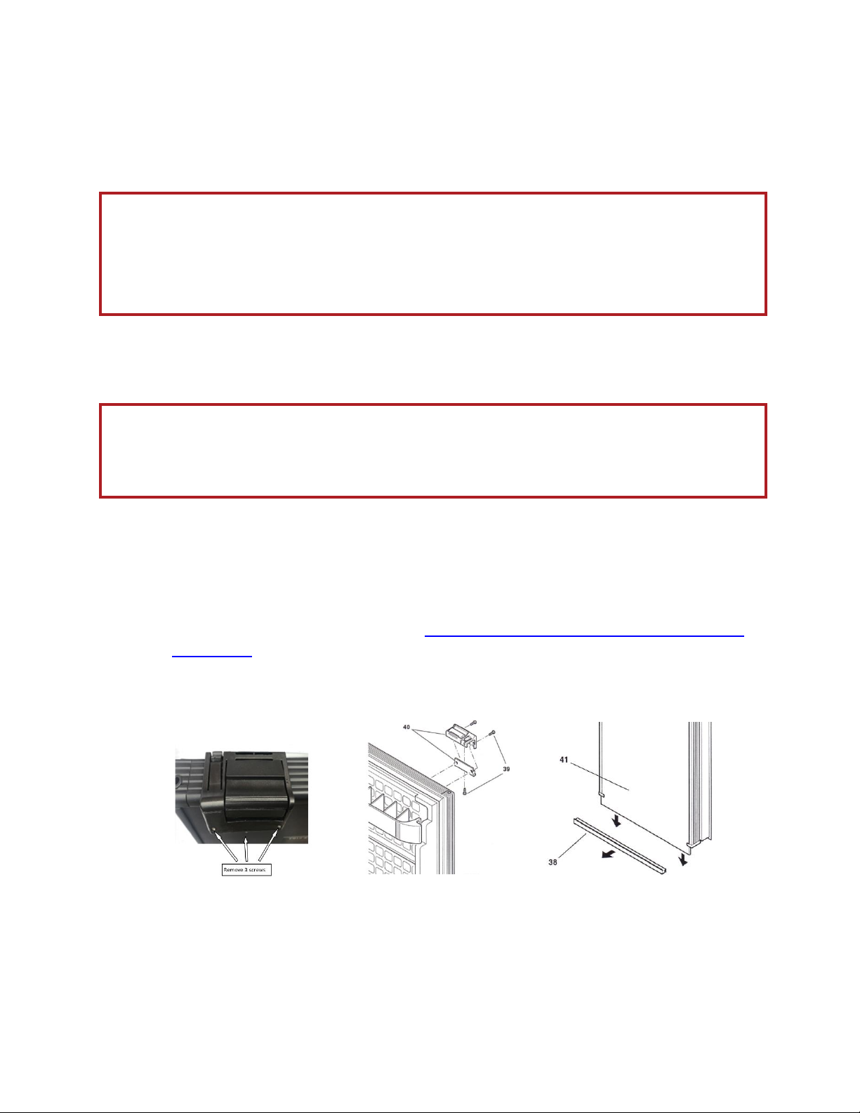
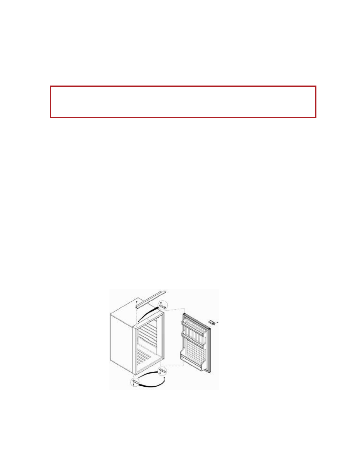
3.4 Replacing the Door Panel (TF49, TF65 and TF130 ONLY)
You can replace the door panel on the TF49, TF65 and TF130 without having to dismantle the door of the
refrigerator, by proceeding as follows:
1. Take out the two screws (39) which hold the handle in place.
2. Remove the profile strip which anchors the panel located at the bottom of the door using a screwdriver as a
lever. Remove the profile strip. See video at https://www.northernfridge.ca/pages/door-panel-
replacement.
3. Pre-drill holes in the new panel to reattach the door latch on the opposite side.
4. Fit in the new panel, letting it slide, and put back the profile strip and door latch.
WARNING!
Never connect bare electric wire(s) and use only connectors of a size suitable to the cross section of the cable
being used.
Never connect the refrigerator power to a cigarette lighter plug. Always connect directly to the battery.
Figure 3.6.1: Replacing Door Panel
Warning
The front panel on the TFDR49 is solid and cannot be replaced. Front panel options include Black (TFDR49DC-
BL) and stainless steel (TFDR49DC-SS).
TruckFridge Built-in User Manual
Updated 5 July 2020 Page 14
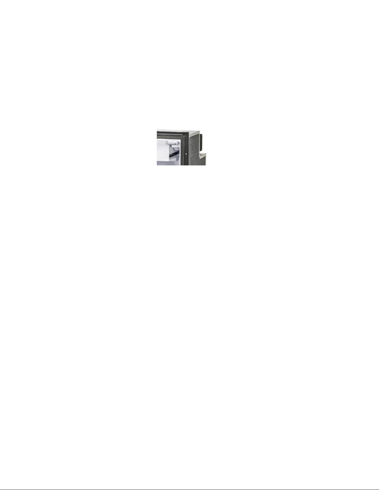
3.5 Reversing the Door Opening (TF49, TF65 and TF130 Only)
The TruckFridge door can open from either the right or left. To change the side, move the hinges and door latch as
shown in Figure 3.7..1 “Reversing Door Opening”below. Image of refrigerator shown is generic and may not
represent your exact model, however the procedure is similar.
1Remove (3 x ¾”) screws from top black flange and remove.
2Remove (4 x3/4”) screws holding top door bracket and remove. CAUTION. Remove rubber washer/”O” ring
and put aside so as not to lose it.
3Remove door.
4Place fridge on its side and remove (4 x 3/4”) screws holding bottom door bracket and remove. CAUTION.
Remove rubber washer(s)/”O” ring and put aside so as not to lose it.
5Remove (4 x 3/4”) bottom flat kick bracket (no pin) from opposite side of bottom door bracket and replace
on opposite side using same (4 x 3/4”) screws. Do not over tighten.
6Replace bottom door bracket to opposite side using (4 x 3/4”) screws. Do not over tighten.
7Turn fridge back upright.
8Replace rubber washer/”O” ring onto bottom door bracket pin.
9Replace door into bottom door bracket pin and then attach upper door bracket pin into door using the
rubber washer/”O” ring.
10 Replace upper door bracket using (4 x 3/4”) screws. Tighten only after the door has been aligned correctly
to open and close easily. Do not over tighten.
11 Replace top flange using (3 x ¾”) screws. Do not over tighten.
12 Remove (2 x 7/8”) screws from front of door latch and remove door latch. Note. Do not remove bottom
screw.
13 Reposition door latch to opposite side. Using a 5/64” drill or sharp awl, drill or punch two new holes in front
panel using door latch to located position of holes. Replace latch with (2 x 7/8”) screw.
Figure 3.7.1: Reversing Door Opening
WARNING.
Turn fridge OFF (disconnect 12V plug from battery). Failure to do so can damage the compressor and void
warranty.
TruckFridge Built-in User Manual
Updated 5 July 2020 Page 15
4.0 FEATURES
4.1 Setting the Inside Temperature
The TruckFridge refrigerators are provided with a manual thermostat. Turn it clockwise to lower (7 lowest) the temperature
and turn it counter-clockwise (1 highest) to raise the temperature and activate the ON-OFF switch in its end position (0). The
knob of the thermostat is located inside the refrigerator.
4.2 Filling
Do not put hot food into the refrigerator. Place the products in a position where they do not hit each other or break while
the vehicle is moving. Make sure the door is always well closed and reduce opening time to a minimum to reduce power
consumption.
4.3 Defrosting
Defrosting must be carried out when the ice layer is thicker than 3.2 mm (1/8”). Set the thermostat at the OFF position. While
defrosting, keep food and beverages in a cool place. DO NOT USE ANY SHARP METAL OBJECT TO REMOVE THE ICE OR
FROST. Do not start the refrigerator up again until it is completely defrosted and dry. Also empty the tray under the freezer
compartment.
5.0 MAINTENANCE
The TruckFridge refrigerators have a completely watertight cooling system, and do not need any maintenance or reloading of
the coolant. The compressor is of a domestic type, is highly efficient and has an extraordinarily long life. General maintenance
merely consists of;
•routinely cleaning the condenser from dust, at least once a year. Use a soft brush and no hard object.
•regularly clean the inside and outside of the refrigerator using only warm water and a neutral detergent.
Subsequent to washing, rinse with clean water and dry thoroughly using a soft cloth.
•Do not use the following: special glass and mirror cleaning products, liquid, powder, or spray detergents, alcohol,
ammonia or abrasive products.
•If you are not using the minibar, we suggest cleaning it well inside and leaving the door ajar to ventilate the interior.
To do so, release the lock of the door using a coin or a small screwdriver.
5.1 Useful Advise
1. If the TruckFridge does not work properly, check the following before calling customer support;
a. make sure power is not missing.
Figure 2.1.5.1: TruckFridge Thermostat
TruckFridge Built-in User Manual
Updated 5 July 2020 Page 16
b. the voltage which reaches the ECU is equal to the one shown on the plate (minimum 11 volts, maximum 14
volts) .
c. the connections have the proper polarity and are secure.
d. the condenser fan is not jammed or obstructed.
e. the refrigerating unit is not near a source of heat.
f. the in-line fuse mounted on the feeding line is not blown.
2. Heavy frost buildup can be caused by several factors:
1Warm foods introduced into the freezer or fridge section.
2Fridge door frequently opened and closed (especially in a high humidity environment).
3Fridge door not properly aligned with fridge body as to affect the rubber seals ability to seal as designed.
4Failure of the putty seal between the back wall of the fridge and the evaporator tube. Would need to be
examined and resealed with existing putty.
5Certain foods, mainly leafy vegetables, have a tendency to cause ice to form faster due to their high moisture
content.
Note: If the ice builds up more than 1/8 inch on either side, it can interfere with the freezer door opening and
shutting properly and can cause the freezer door to pop loose and reduces the ability of the fridge to cool properly
and the fridge will need to be defrosted. It goes without saying, the fridge needs to defrost naturally by turning off
power and opening the door.
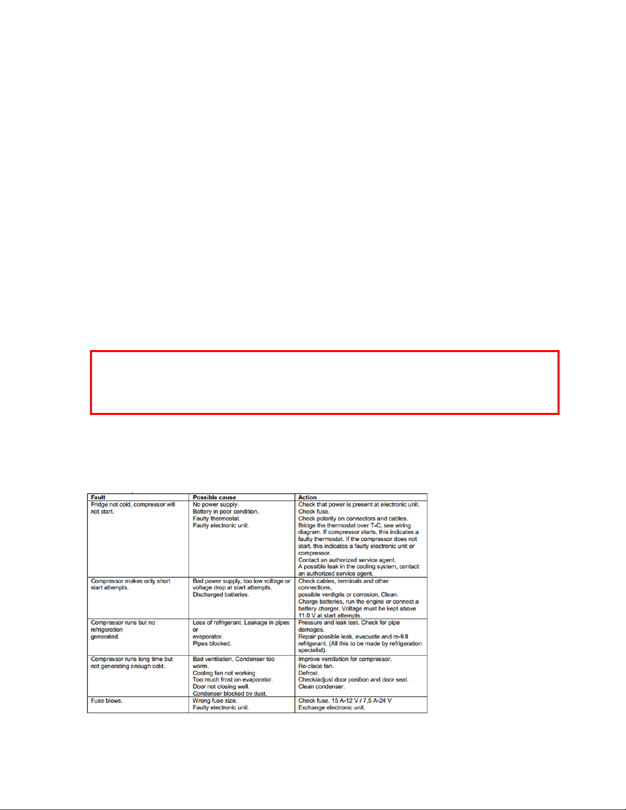
6.0 TROUBLESHOOTING
6.1 Fault Finding
6.2 Self-Diagnostics
WARNING !
The user needs to be reminded to not use ANY object to pry ice loose or to use any heat source to speed up
the defrost process as damage will occur. Make sure the fridge is thoroughly dry inside before restarting and
remove excess moisture from any food and/or food packaging.
TruckFridge Built-in User Manual
Updated 5 July 2020 Page 17
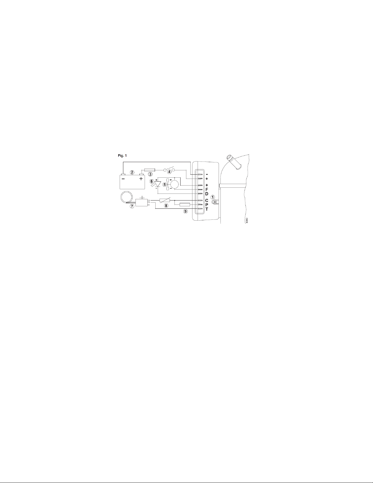
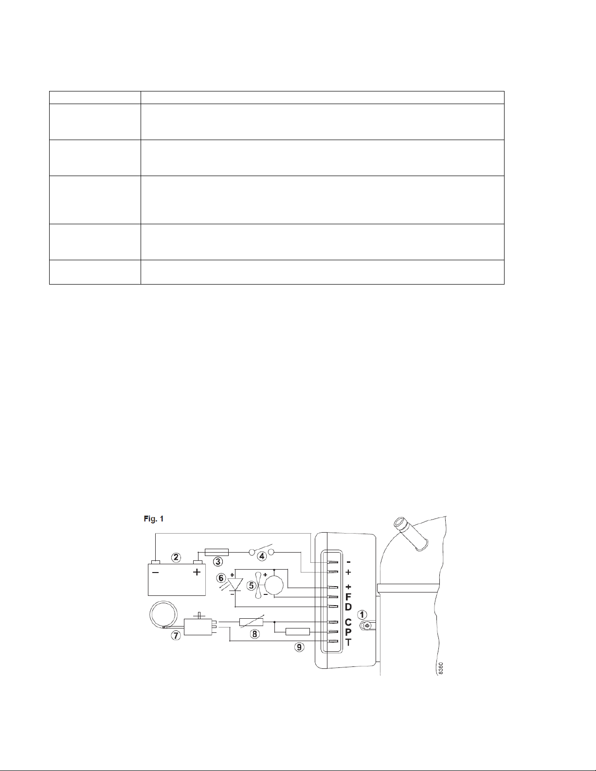
LED (optional) See Figure 6.2 TruckFridge 12VDC 101N0212 ECU Electrical Schematic
A 10mA light emitting diode (LED) (6) can be connected between the terminals + and D. In case the electronic unit
records an operational error, the diode will flash a number of times. The number of flashes depends on what kind of
operational error was recorded. Each flash will last ¼ second. After the actual number of flashes there will be a delay
with no flashes, so that the sequence for each error recording is repeated every 4 seconds.
Diagnostic Procedure
1. Disconnect thin black wire from terminal marked (-).
2. Reconnect to terminal marked (D).
3. Observe the number of flashes of the interior LED light bulb.
4. See Figure 6.2.2: Error Code Summary Table for error code description.
5. Reconnect thin black wire to terminal marked (-).
Figure 6.2.1: TruckFridge 12VDC 101N0212 ECU Electrical Schematic
TruckFridge Built-in User Manual
Updated 5 July 2020 Page 18
No. of flashes
Error Type
5
Thermal cut-out of electronic unit
(If the refrigeration system has been too heavily loaded, or if the ambient temperature is
high, the electronic unit will run too hot).
4
Minimum motor speed error
(If the refrigeration system is too heavily loaded, the motor cannot maintain minimum
speed 1,850 rpm).
3
Motor start error
(The rotor is blocked or the differential pressure in the refrigeration system is too high
(>5 bar)).
2
Fan over-current cut-out
(The fan loads the electronic unit with more than 1A peak).
1
Battery protection cut-out
(The voltage is outside the cut-out setting)
Table 6.2.2: Error Code Summary Table
6.3 Thermostat Test
If the thermostat is defective the refrigerator fan and compressor may not operate. To test the thermostat please
follow the following test procedure. See Figure 6.3.1: Thermostat Test Procedure Below.
1. Disconnect the “Blue” wire from the “T” terminal.
2. Disconnect the single “Brown” wire from the “P” terminal.
3. Reconnect the single “Brown” wire to the “T” terminal
4. If the fan and compressor turn on, the thermostat is defective
5. If the fan and compressor do not turn on, contact Northern Fridge support for service
6. Reconnect the “Blue” wire to the “T” terminal and reconnect single “Brown” wire to the “P” terminal
Figure 6.3.1: Thermostat Test Procedure
TruckFridge Built-in User Manual
Updated 5 July 2020 Page 19
7.0 SPECIFICATIONS
Note. If in doubt about the model for your truck, always confirm by measuring the height, width and depth of the
cabinet opening before ordering.
Please note that models, prices, and availability is subject to change without obligation or notice.
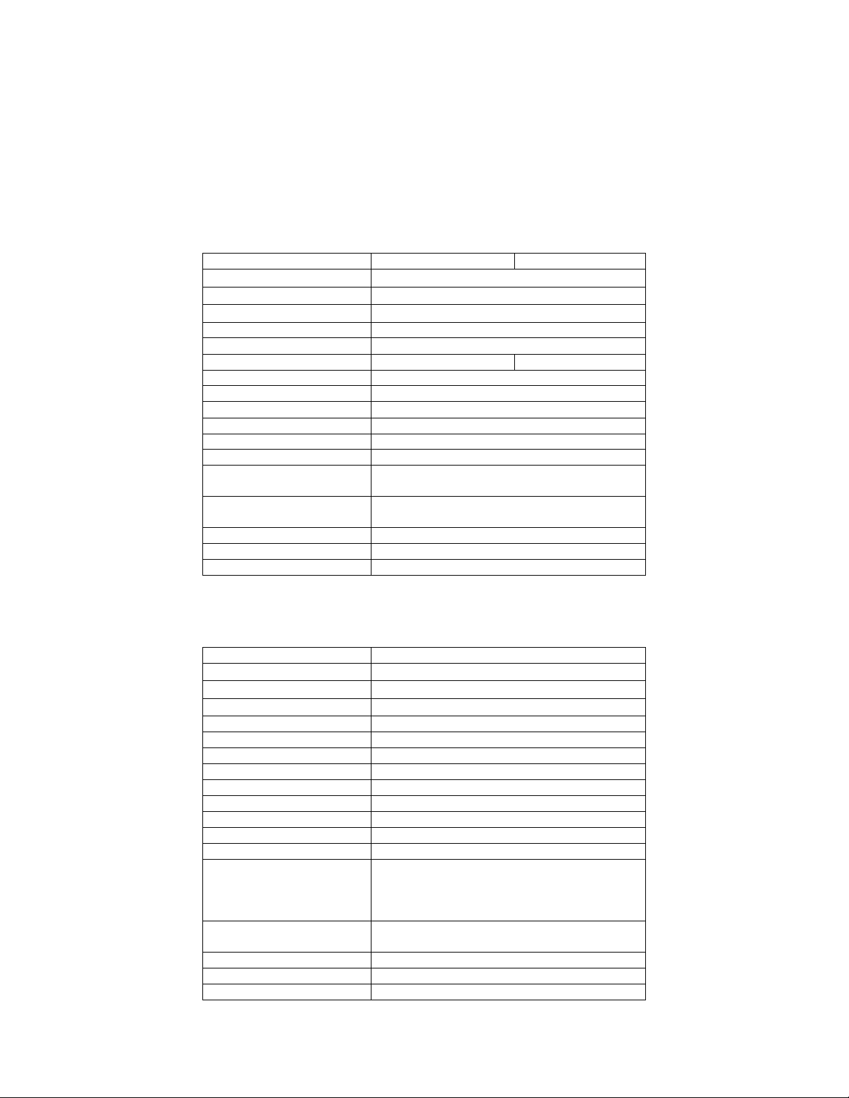
7.1 Truckfridge Model TF49
Description
TF49DC
TF49ACDC
Outside Dimensions (inches)
20.5H x 15"W x 18"D
Inside Dimensions (inches)
17.5” H x 12.75”W x 16”D
Freezer
9"W x 3"H x 8.5"D
Total Capacity
49 litre / 1.73 cu. ft.
Freezer
8 Liter / .14 Cu.Ft.
Nominal voltage
12-24Vdc
12-24Vdc, 110-220Vac
Nominal input power
60 watt/hour (5 amp/hour)
Average power consumption
40 Amps/24h. (1.7 amp/hour)
In-line fuse
15A (12VDC), 7.5A (24VDC)
Refrigerant
R134a
Temperature Range
+2oC to -7oC (35oF to 18oF)
Air cooling
Forced with fan
Standard Features
Interior light, adjustable thermostat, (1) wire
shelves, (2) door shelves and low voltage cut-out.
Colour
Cabinet (Black); Interior (White); Door Panel (Black
Plexiglass)
EMC conformity
Yes
Net weight (lbs)
35 lbs
Warranty
Two (2) year parts and labour
7.2 Truckfridge Model TFDR49DC-BL
Description
TFDR49DC-BL
Outside Dimensions (inches)
20.5H x 15.375 "W x 20.5"D
Inside Dimensions (inches)
Freezer
6.5”H x 11”W x 6.5”D
Total Capacity
49 litre / 1.73 cu. ft.
Freezer
7.33 Liter / .26 Cu.Ft.
Nominal voltage
12-24Vdc
Nominal input power
60 watt/hour (5 amp/hour)
Average power consumption
40 Amps/24h. (1.7 amp/hour)
In-line fuse
15A (12VDC), 7.5A (24VDC)
Refrigerant
R134a
Temperature Range
+2oC to -7oC (35oF to 18oF)
Air cooling
Forced with fan
Standard Features
Sliding drawer top opening, separate fridge /
freezer compartments, interior light, adjustable
thermostat, (2) compartment dividers, low voltage
cut-out and installation frame/kit
Colour
Cabinet (Black); Interior (White); Door Panel (Black
Plexiglass)
EMC conformity
Yes
Net weight (lbs)
55 lbs
Warranty
Two (2) year parts and labour
TruckFridge Built-in User Manual
Updated 5 July 2020 Page 20
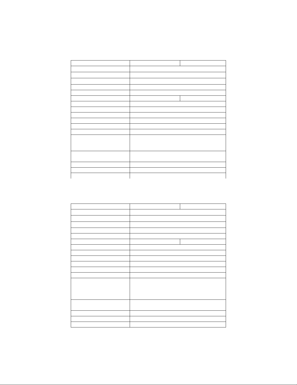
7.3 Truckfridge Model TF65
Description
TF65DC
TF65ACDC
Outside Dimensions (inches)
21H x 17.75"W x 18.375"D
Inside Dimensions (inches)
18” H x 15.675”W x 17”D
Freezer
9.5"W x 3"H x 8.5"D
Total Capacity
65 litre / 2.3 cu. ft.
Freezer
8 Liter / .14 Cu.Ft.
Nominal voltage
12-24Vdc
12-24Vdc, 110-220Vac
Nominal input power
60 watt/hour (5 amp/hour)
Average power consumption
40 Amps/24h. (1.7 amp/hour)
In-line fuse
15A (12VDC), 7.5A (24VDC)
Refrigerant
R134a
Temperature Range
+2oC to -7oC (35oF to 18oF)
Air cooling
Forced with fan
Standard Features
Interior light, adjustable thermostat, (1) wire
shelves, (2) door shelves and low voltage cut-out
and installation frame/kit.
Colour
Cabinet (Black); Interior (White); Door Panel (Black
Plexiglass)
EMC conformity
Yes
Net weight (lbs)
40 lbs
Warranty
Two (2) year parts and labour
7.4 Truckfridge Model TF130
Description
TF130DC
TF130ACDC
Outside Dimensions (inches)
29.5H x 20.25"W x 20.75"D
Inside Dimensions (inches)
26” H x 18”W x 13.75”D
Freezer
8"W x 3.5"H x 13.75"D
Total Capacity
119 litre / 4.2 cu. ft.
Freezer
6.3 Liter / .22 Cu.Ft.
Nominal voltage
12-24Vdc
12-24Vdc, 110-220Vac
Nominal input power
60 watt/hour (5 amp/hour)
Average power consumption
40 Amps/24h. (1.7 amp/hour)
In-line fuse
15A (12VDC), 7.5A (24VDC)
Refrigerant
R134a
Temperature Range
+2oC to -7oC (35oF to 18oF)
Air cooling
Forced with fan
Standard Features
Lower pull out drawer, interior light, adjustable
thermostat, (3) wire shelves, (1) glass shelf, (3)
door shelves, low voltage cut-out and installation
frame/kit.
Colour
Cabinet (Black); Interior (White); Door Panel (Black
Plexiglass)
EMC conformity
Yes
Net weight (lbs)
53 lbs
Warranty
Two (2) year parts and labour
This manual suits for next models
8
Table of contents
Other Northern Fridge Refrigerator manuals


