Northern Telecom Meridian Companion User manual

Companion Diagnostic Software
User Guide
P0887339
Issue 02 Standard
November 1998
© 1998 Northern Telecom
All rights reserved
Printed in the United States of America
Companion is a trademark of Northern Telecom.


P0887339 Issue 02 Standard Companion Diagnostic Software User Guide 1
Contents
Companion Diagnostic Software basics 5
CDS package checklist 6
Equipment checklist 6
Local access equipment 6
Remote access equipment using the RAD internal modem 7
Remote access equipment using a RAD external modem 7
Optional equipment 8
Connect the equipment 8
Local access connections 9
To connect the PC to the RAD 9
Remote access connections using the RAD internal modem 10
Remote access connections using a RAD external modem 13
Wireless system programming 15
Local access programming 16
Remote access programming using the RAD internal modem 16
Remote access programming using a RAD external modem 17
Make a working copy 17
Installing and using CDS on your hard drive 17
Using CDS from your floppy drive 18
Files needed by CDS 18
Site administration 21

2
Companion Diagnostic Software User Guide P0887339 Issue 02 Standard
Setting up CDS for a new site 22
Local access 22
Remote access 24
Files created by setting up a new site 26
Changing the administration data of an existing site 26
Local access 26
Remote access 28
Using Companion Diagnostic Software 33
Selecting data 36
Automatic system configuration 37
Exiting CDS 38
Display screen components 39
A Typical CDS Session 40
Keyboard functions 41
Making menu selections 42
Files created when using CDS 42
Display screens 43
Command map 44
Main menu 45
Diagnosis Option 45
Monitor Option 46
Utilities Option 46
Diagnosis 47
Automatic System Diagnosis 47
Diagnosis Menu Options 52
Quality of Service 52
Quality of Service components 53
System Faults components 59
Radio Signals 66
Cell Signals 71
Interference 74
Traffic 76

3
P0887339 Issue 02 Standard Companion Diagnostic Software User Guide
Monitor 85
Background RSSI 86
CRC Errors 90
Reset RIM 91
Query BS Faults 94
Clear BS Faults 96
Clear Counters 97
Utilities 99
View System Configuration 100
Create Dataset 101
Delete Dataset 102
Change Language 103
Appendix A 105
Equipment requirements 106
CDS software 106
PC 106
RAD 106
PC modem 107
RAD external modem 107
RS232 cable 108
RAD TCM cable 108
RS232 null modem cable 108
Public switch line cable 109
PC modem initialization string 109
Appendix B 111
Diagnosis Action Recommendations 112
How to report a problem 112
System Faults 112
Traffic 120
Interference 123
Radio Signals 124
Appendix C 127
CDS Error Messages 128
Appendix D 131
RUNCDS: Running CDS in Batch Mode 132
RUNCDS Command Line Syntax 134

4
Companion Diagnostic Software User Guide P0887339 Issue 02 Standard
The CDS Macro Language 135
Macro Language Rules 135
CDS Macro Language Commands 135
Examples 138
Appendix E 143
CDS DOS Hard Drive Disk File Management 144
Files needed by CDS 144
Files created by administering a new site 144
Files created when using CDS 145
Saved Datasets 146
DOS File Summary 149
Index 151

P0887339 Issue 02 Standard Companion Diagnostic Software User Guide 5
Companion Diagnostic Software basics
• Introduction
• Checklists
• Connections
• Modem Access
• Installing CDS

6 Companion Diagnostic Software basics
Companion Diagnostic Software User Guide P0887339 Issue 02 Standard
About Companion Diagnostic Software for PCI
Companion Diagnostic Software (CDS) for CT2Plus allows you to
examine the operating characteristics of a wireless system while the
system is operating at a customer site. The CDS application runs on
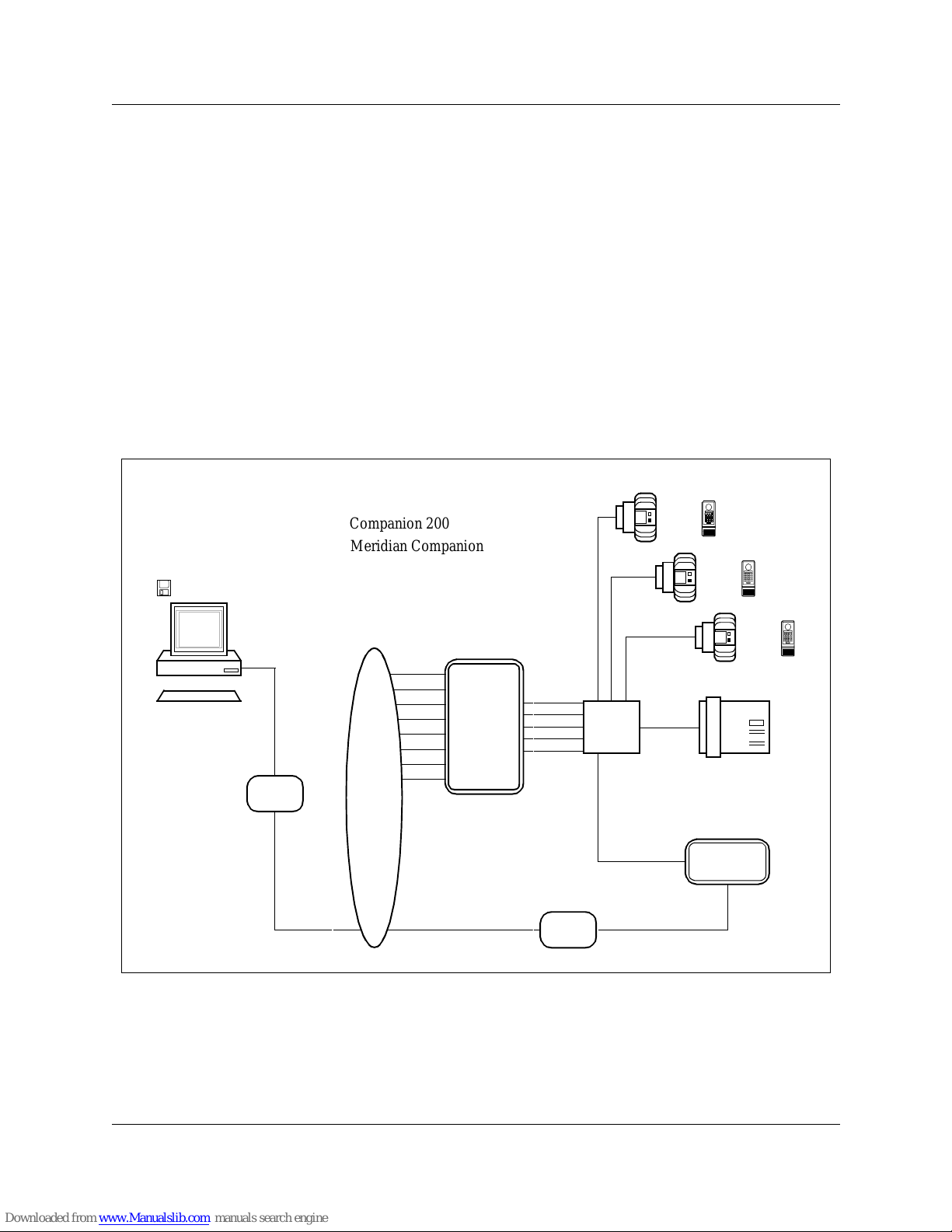
a personal computer (PC). You can use it locally at the customer site
or remotely from another location. When youuse remote access, the
PC interfaceswith thewireless systemindirectly via modems. When
you use local access, the PC interfaces with the wireless system
directly without modems. CDS performs automatic system
configuration and automatic system diagnosis. It also presents on
your PC screen data derived from wireless operation. The displays
contain various levels of detail and are in the form of bar charts and
statistical tables, with accompanying commentaries.
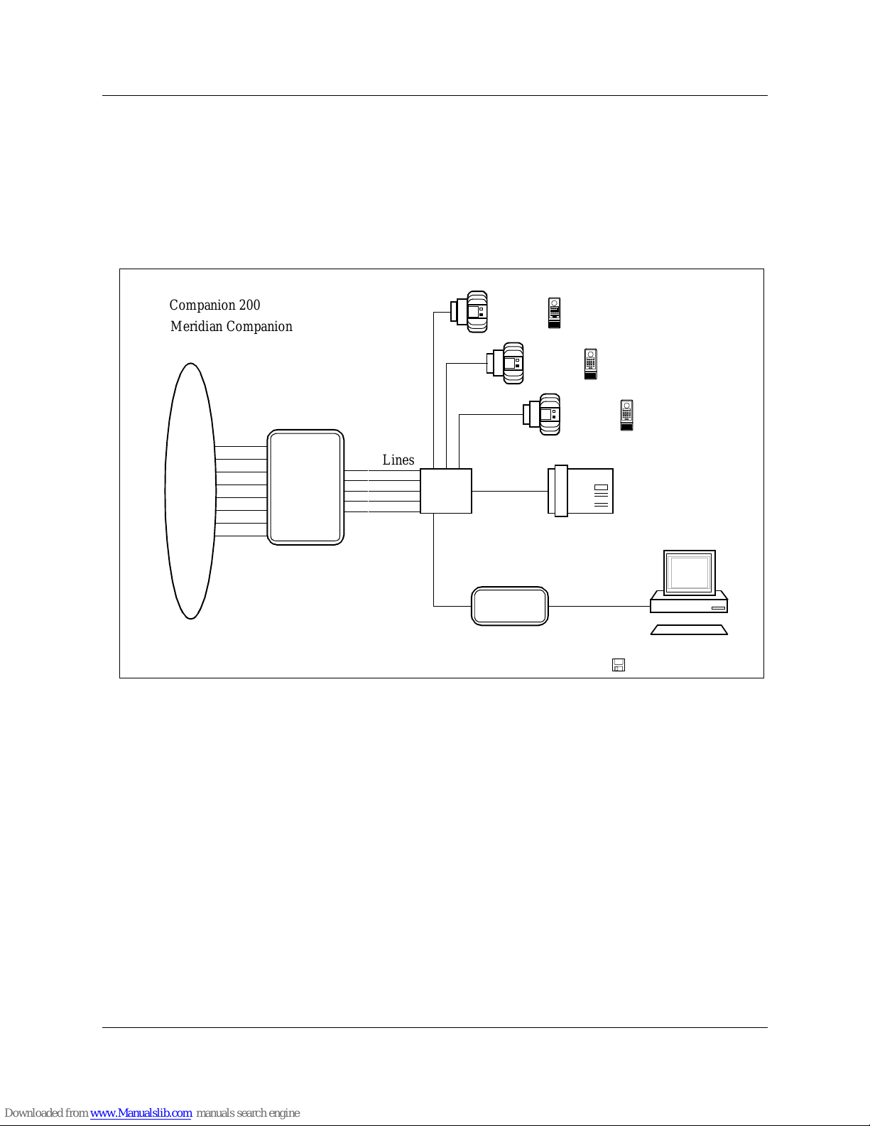
The two radio transceivers in a Base Station operate in an allocated
frequency spectrum. Base Stations are grouped into cells, a cell may
have two or more radios in it depending upon the number of Base
Stations making up the cell. These cells overlap each other to ensure
continuous radio coverage throughout the desired coverage area. In
each cell, at any one time, one radio may be used to provide a
commonsignallingchannel(CSC)whichlocates andtracks portable
movements. Companion Diagnostic Software provides access to
information on the operating characteristics of both regular traffic
and CSC radios.
CDS package checklist
The CDS package includes the following:
• high density 3 1/2" CDS diskette
• Companion Diagnostic Software User Guide
Equipment checklist
The following is a checklist of equipment requirements for each type
of connection. For more detailed descriptions of the equipment
required, see Appendix A of this guide.
Local access equipment
To install and use CDS with local access, you must have the
following:

Companion Diagnostic Software basics 7
P0887339 Issue 02 Standard Companion Diagnostic Software User Guide
• Remote Access Device (RAD)
• RAD Time Compression Multiplexing (TCM) cable, to connect
the RAD to the Controller
• IBM compatible PC (386 processor or greater)
• RS232 cable, to connect the PC to the RAD
Remote access equipment using the RAD internal modem
To install and use CDS with remote access via the RAD internal
modem, you must have the following:
•RAD
• RAD TCM cable, to connect the RAD to the Controller
• IBM compatible PC (386 processor or greater)
• PC modem
• RS232 cable, to connect the PC to the PC modem
• Public switch line cable, to connect the PC modem to the public
switch
Remote access equipment using a RAD external modem
To install and use CDS with remote access via the RAD external
modem, you must have the following:
•RAD
• RAD TCM cable, 32 in (80 cm), to connect the RAD to the
Controller
• IBM compatible PC (386 processor or greater)
• PC modem
• RS232 cable, to connect the PC to the PC modem
• Public switch line cable, to connect the PC modem to the public
switch
• RAD external modem
• RS232 null modem cable, to connect the RAD to the RAD
external modem

8 Companion Diagnostic Software basics
Companion Diagnostic Software User Guide P0887339 Issue 02 Standard
Optional equipment
You may want to have the following hardware:
• high density 3 1/2" diskette to make a working copy of the
application
• hard drive for storing large amounts of data
• portable computer with battery power supply for greater mobility
Connect the equipment
You can make two types of equipment connections to examine
wireless system operation using CDS. A local access connection
may be made using an RS232 cable at the customer site, or a remote
connection may be made through a PC modem to use CDS at a
location other than the customer site.
Note: The RAD cannot be programmed if an RS232 cable is
connected to its serial port. Ensure that the required RAD
programming has been done before connecting the RS232
cable to the RAD serial port.

Companion Diagnostic Software basics 9
P0887339 Issue 02 Standard Companion Diagnostic Software User Guide
Local access connections
Figure 1 shows the connections that you must make to examine a
wireless system using CDS atthe customer site.Referto the Remote
Access Device Installation Guide if yourequire more detail on RAD
hardware connections or programming.
Figure 1: Overview of CDS local connections and wireless system
To connect the PC to the RAD
1. Connect one end of the RS232 cable to serial port 1 or 2 on the
PC using a connector that matches your PC’s port.
2. Place the PC within 100 feet (30 meters) of the RAD.
3. Connect the other end of the RS232 cable to theserial port on the
RAD using a female 25-pin connector.
To connect the RAD to the Controller:
1. Connect oneend of theRAD TCMcable to theRJ-11 port onthe
back of the RAD using the RJ-11 connector.
2. Place the RAD near the distribution block and within 100 feet
(30 meters) of the Controller.
Public
Switch
or
PBX
Controller
TCM
RAD PC
Keyboard
Companion
Diagnostic
Software
CDS Application
Administration
Terminal (M7310)
Distribution
Block
RS232 Cable
(max. 100 ft)
RAD
Base Stations
Public
Switch
or
PBX
Access
Lines
Portables
TCM
Cable
Companion 200
Lines
Meridian Companion

10 Companion Diagnostic Software basics
Companion Diagnostic Software User Guide P0887339 Issue 02 Standard
Note: Place the RAD as close as possible to the distribution block.
Make sure that the combined length of the RAD TCM cable
and the TCM lines between the distribution block and the
Controller is less than 100 feet (30 meters).
3. Connect the loose wires on the other end of the RAD TCM cable
to an allowable free port (one of the first five TCM ports) at the
distribution block.
Note: Although any of the first five TCM ports are allowable for the
purposes of CDS, if you also intend to use the backup/restore
feature in Companion Manager, youshoulduse the first TCM
port.
Ensure that the RAD TCM cable is free of bridge-taps and loading
coils.
Remote access connections using the RAD internal modem
Figure 2 shows the connections that you must make to examine a
wireless system using CDS from a remote location via the RAD
internal modem. One of the lines into the Controller is dedicated to
the RAD. This line is not available for other devices. If a dedicated
line is not available through the Controller, the RAD can share a line
with another device, although this is not recommended.

Companion Diagnostic Software basics 11
P0887339 Issue 02 Standard Companion Diagnostic Software User Guide
The RAD must be programmed to answer the line automatically
when the PC dials in through the public switch. Refer to the Remote
Access Device Installation Guide if yourequire more detail on RAD
hardwareconnectionsor programming. Ifyou requiremore detailon
wireless system hardware connections, refer to the wireless system
documentation.
Figure 2: Overview of CDS remote connections using the RAD internal modem
Public
Switch
or
PBX
Controller
TCM
RAD
PC
Companion
Diagnostic
Software
CDS Application
Administration
Terminal
Distribution
Block
RS232
RAD
Base Stations
Public
Switch
or
PBX
Access
Lines
Portables
Lines
(M7310)
Cable
(max.
100 ft)
PC
modem
Public
Switch
Line
Keyboard
TCM
Cable
Companion 200
Meridian Companion

12 Companion Diagnostic Software basics
Companion Diagnostic Software User Guide P0887339 Issue 02 Standard
On-site connections required for remote access (with internal
modem)
To connect the RAD to the Controller:
1. Connect oneend of theRAD TCMcable to theRJ-11 port onthe
back of the RAD using the RJ-11 connector.
2. Place the RAD near the distribution block and within 100 feet
(30 meters) of the Controller.
Note: Place the RAD as close as possible to the distribution block.
Make sure that the combined length of the RAD TCM cable
and the TCM lines between the distribution block and the
Controller is less than 100 feet (30 meters).
3. Connect the loose wires on the other end of the RAD TCM cable
to an allowable free port (one of the first five TCM ports) at the
distribution block.
Note: While any of the first five TCM ports are allowable for the
purposes of CDS, if you also intend to use the backup/restore
feature in Companion Manager, youshould use the firstTCM
port.
Ensure that the RAD TCM cable is free of bridge-taps and
loading coils.
Off-site connections required for remote access (with internal
modem)
PC serial ports 1 and 2 are supported by CDS.
To connect the PC to an external PC modem:
1. Connect one end of the RS232 cable to serial port 1 or 2 on the
PC using a connector that matches your PC’s port.
2. Connect the other end of the RS232 cable to theserial port on the
PC modem using a connector that matches the modem serial
port.
Note: The maximum length of an RS232 cable is 100 feet
(30 meters).
To connect the PC modem to the public switch:
1. Connect one end of the publicswitch line cable to the RJ-11 port
on the PC modem using an RJ-11 connector.
2. Connect the other end of the public switch line cable to the
public switch network.

Companion Diagnostic Software basics 13
P0887339 Issue 02 Standard Companion Diagnostic Software User Guide
Remote access connections using a RAD external modem
To examine a wirelesssystem using CDS from a remote location via
aRADexternalmodem,no lineinto thecontrollerisdedicatedto the
RAD. A line connects the RAD external modem directly to the
public switch or Private Branch Exchange (PBX), bypassing the
Controller. The PC dials the telephone number assigned to this line.
The external modem is connected to the RAD by an RS232 null
modem cable. See Figure 3 for the connections you must make to
examine a wireless system using CDS from a remote location using
a RAD external modem.
Note: Only 9600 baud can be supported with the external modem.
Figure 3: Overview of CDS remote connections using a RAD external modem
Public
Switch
or
PBX
Controller
TCM
RAD
PC
Companion
Diagnostic
Software
CDS Application
Administration
Terminal
Distribution
Block
RS232
RAD
Base Stations
Public
Switch
or
PBX
Access
Lines
Portables
lines
TCM
(M7310)
Cable
(max.
100 ft)
PC
modem
Public
Switch
Line
Keyboard
Public Switch
RAD
RS232 Null
Modem Cable
or PBX Line
External
Modem
Cable
Companion 200
Meridian Companion

14 Companion Diagnostic Software basics
Companion Diagnostic Software User Guide P0887339 Issue 02 Standard
On-site connections required for remote access (with external
modem)
To connect a RAD to the Controller:
1. Connect one end of a RAD TCM cable to the RJ-11 port on the
back of a RAD using the RJ-11 connector.
2. Place the RAD near the distribution block and within 100 feet
(30 meters) of the Controller.
Note: Place the RAD as close as possible to the distribution block (a
32 inch (80 centimeter) cable has been provided). Make sure
that the combined length of the RAD TCM cable and the
TCM lines between the distribution block and the Controller
is less than 100 feet (30 meters).
3. Connect the loose wires on the other end of the RAD TCM cable
to an allowable free port (one of the first five TCM ports) (refer
to the Remote Access Device Installation Guide) at the
distribution block.
Note: Although any of the first five TCM ports are allowable for the
purposes of CDS, if you also intend to use the backup/restore
feature in Companion Manager, youshould use the firstTCM
port.
Ensure that the RAD TCM cable is free of bridge-taps and loading
coils.
To connect a RAD to a RAD external modem:
1. Connect one end of the RS232 null modem cable to the serial
port on the RAD using a female 25-pin connector.
2. Connect the other end of the RS232 null modem cable to the
serial port on the RAD external modem using an appropriate
connector.
To connect a RAD external modem to the public switch or PBX:
1. Connect one end of the line cable to the RJ-11 port on the RAD
external modem using an RJ-11 connector.
2. Connect the other end of the line cable to the public switch or
PBX.
Note: Only 9600 baud can be supported with the external modem.

Companion Diagnostic Software basics 15
P0887339 Issue 02 Standard Companion Diagnostic Software User Guide
Off-site connections required for remote access (with external
modem)
PC serial ports 1 and 2 are supported by CDS.
To connect the PC to an external PC modem:
1. Connect one end of the RS232 cable to serial port 1 or 2 on the
PC using a connector that matches your PC’s port.
2. Connect the other end of the RS232 cable to theserial port on the
PC modem using an appropriate connector.
Note: The maximum length of an RS232 cable is 100 feet
(30 meters).
To connect the PC modem to the public switch:
1. Connect one end of the publicswitch line cable to the RJ-11 port
on the PC modem using an RJ-11 connector.
2. Connect the other end of the public switch line cable to the
public switch network.
Wireless system programming
The following is a summary of the wireless system programming
required for a local or remote connection. This programming is
performed on the wireless system’s Administration Terminal, and
should be recorded in the Programming Record of the Remote
Access Device Installation Guide. Programming must be completed
at the customer site before you can use CDS. Refer to the Remote
Access Device Installation Guide if yourequire more detail on RAD
programming. Refer to the wireless system documentation if you
require more detail on wireless system programming.
Note:ARAD cannotbe programmedifan RS232cableis connected
to its serial port. Ensure that the required RAD programming
has beendone before connecting the RS232 cable to the RAD
serial port.
Note: The System ID must be programmed for the RAD before you
can proceed. Refer to the Remote Access Device Installation
Guide for instructions on how to program the System ID for
the RAD. The RAD password defaults to the System ID.

16 Companion Diagnostic Software basics
Companion Diagnostic Software User Guide P0887339 Issue 02 Standard
Note: Displayed data is referenced to the time and date of the
system. To ensure accurate referencing, use the
Administration Terminal to set the time correctly.
Local access programming
Ensure that the following steps have been completed before setting
up a new CDS site with local access:
• System ID programmed for the RAD
Remote access programming using the RAD internal modem
Ensure that the following steps have been completed before setting
up a new CDS site with remote access using the RAD internal
modem:
• the line into the wireless system dedicated to the RAD (note the
telephone number)
• System ID programmed for the RAD
• line type programmed as Key Service Unit (KSU) for the RAD
• allowable line number programmed forthe RAD (refer to Remote
Access Device Installation Guide)
• Auto Answer programmed for the RAD
The Auto Answer settings programmed depend on how the RAD
internal modem is used.
If a line is dedicated to the RAD:
• set auto answer ‘on’ for the RAD
• set the number of rings before auto answer to ‘1’
If a line is shared with the RAD:
• set auto answer ‘on’ for the RAD
• set the number of rings before auto answer to a number between
‘1’ and ‘10’
Note: Beware of any telephony application that may cause the call
to be answered before the RAD answers automatically (e.g.,
Call Forward or Voice Mail).
In the case of a shared line, an alternate approach, is to set RAD Auto
Answer ‘off’ for normal wireless system operation. When you need

Companion Diagnostic Software basics 17
P0887339 Issue 02 Standard Companion Diagnostic Software User Guide
to initiate a diagnostic session, contact someone at that site and ask
them to program RAD Auto Answer ‘on’, with the number of rings
before Auto Answer to ‘1’. You may then make the modem call to
the site and perform the diagnostics. At the end of the session,
contact the on-site person and ask them to program RAD Auto
Answer ‘off’ again.
Remote access programming using a RAD external modem
Ensure that the following have been completed before setting up a
new CDS site with remote access using a RAD external modem:
• publicswitchlineconnecteddirectlyto theRAD externalmodem
(note the telephone number)
• System ID programmed for the RAD
Note: The only modem speed supported for this configuration is at
9600 bps.
Make a working copy
Make a working copy of the original CDS diskette. Use the working
copy diskette to install CDS on your hard drive or to use CDS from
your floppy drive. Store your original diskette as backup.
Installing and using CDS on your hard drive
To install CDS on your hard drive:
1. Insert the working copy diskette of CDS into your floppy drive.
Assuming your hard drive is ‘C’ and your floppy drive is ‘A’,
2. At the MS-DOS C:\> command prompt, type:
A:
and press
3. At the prompt A>, type:
CD_SETUP <source-drive> <destination-drive> [-d<lng>]
[-l<lng>]
for example: CD_SETUP A C -D ENG -L FRA
and press
Enter
Enter

18 Companion Diagnostic Software basics
Companion Diagnostic Software User Guide P0887339 Issue 02 Standard
Note: The DOS commands in CD_SETUP and similar applications
are not case-sensitive.
CDS supports more than one language. Currently the two language
choices are:
1. ENG for English.
2. FRA for French.
In the above example both English and French will be installed on
your hard drive. The -d indicates the default language, and -l the
alternate language. English will be set up as the default language to
by used by CDS, CDS_ADM and RUNCDS.
If no language is entered during setup, the language used will be the
default set for your version. If an alternate language is not entered
during setup, only the default language will be installed. During
operation of CDS, the current default language can be changed to
any of the languages that were installed by CD_SETUP. This default
language will then be applied to both RUNCDS and CDS_ADM.
A CDSPLUS directory will be created containing all the files listed
below (see ‘Files needed by CDS’ and also ‘Appendix E’). You can
now use CDS from your hard drive.
Using CDS from your floppy drive
You can use CDS from your floppy drive, but beware of diskette
space limitations. If you plan to use CDS from your floppy drive:
1. Insert the working copy diskette of CDS into your floppy drive.
You can now use CDS from your floppy drive. Ensure that DOS
write protect is off and that the diskette remains in the floppy drive
for the entire CDS session. To set up, follow the same procedure as
for setting up CDS for a new site. See the section on ‘Site
administration’.
Files needed by CDS
The CDS application provides a directory called CDSPLUS at the
highest level on the drive that you have chosen. The following files
are in the CDSPLUS directory and are required to use the
application:
This manual suits for next models
1
Table of contents
Popular Software manuals by other brands

Motorola
Motorola MSP3-CNTRL-SW-1 - Mobility Services Platform Control... installation guide

Braton Group
Braton Group Database Manager user manual

ACRONIS
ACRONIS BACKUP RECOVERY 10 ADVANCED SERVER - quick start guide

Sharp
Sharp AR-P17 Software setupg guide Software setup guide

Sharp
Sharp AR-PB2 Operation manual

Nortel
Nortel 5100 Series Release 2.3.3 user guide

Novell
Novell PLATESPIN ORCHESTRATE 2.0.2 - UPGARDE GUIDE... Installation and configuration guide

Paxar
Paxar Monarch 9860 operating instructions

Yamaha
Yamaha A3000 owner's manual

Alcatel
Alcatel VitalSuite RELEASE 10.3 SP1 datasheet

ACTi
ACTi Network Video Recorder user manual

Epson
Epson PowerLite 1760W Operation guide