NorthStar Explorer 660 User manual

www.northstarnav.com
Explorer 660
Chartplotter and Fishfinder
Installation and Operation Manual

FCC Statement
Note: This equipment has been tested and found to comply with the limits for a Class B digital device,
pursuant to Part 15 of the FCC Rules. These limits are designed to provide reasonable protection against
harmful interference in a normal installation. This equipment generates, uses and can radiate radio
frequency energy and, if not installed and used in accordance with the instructions, may cause harmful
interference to radio communications. However, there is no guarantee that interference will not occur in
a particular installation. If this equipment does cause harmful interference to radio or television reception,
which can be determined by turning the equipment off and on, the user is encouraged to try to correct
the interference by one or more of the following measures:
Reorient or relocate the receiving antenna.
Increase the separation between the equipment and receiver.
Connect the equipment into an output on a circuit different from that to which the receiver is
connected.
Consult the dealer or an experienced technician for help.
A shielded cable must be used when connecting a peripheral to the serial ports.
IMPORTANT SAFETY INFORMATION
Please read carefully before installation and use.
DANGER
This is the safety alert symbol. It is used to alert you to potential
personal injury hazards, Obey all safety messages that follow this symbol to
avoid possible injury or death.
!
WARNING
WARNING indicates a potentially hazardous situation which, if not avoided,
could result in death or serious injury
CAUTION
!
CAUTION indicates a potentially hazardous situation which, if not avoided, could
result in minor or moderate injury.
CAUTION
CAUTION used without the safety alert symbol indicates a potentially
hazardous situation which, if not avoided, may result in property damage.
DISCLAIMER: It is the owner’s sole
responsibility to install and use the instrument
and transducers in a manner that will not cause
accidents, personal injury or property damage.
The user of this product is solely responsible for
observing safe boating practices.
BRUNSWICK NEW TECHNOLOGIES INC. AND ITS
SUBSIDIARIES AND AFFILIATES DISCLAIM ALL
LIABILITY FOR ANY USE OF THIS PRODUCT IN A
WAY THAT MAY CAUSE ACCIDENTS, DAMAGE OR
THAT MAY VIOLATE THE LAW.
Governing Language: This statement,
any instruction manuals, user guides and
other information relating to the product
(Documentation) may be translated to, or
has been translated from, another language
(Translation). In the event of any conflict
between any Translation of the Documentation,
the English language version of the
Documentation will be the official version of the
Documentation.
This manual represents the Explorer 660
as at the time of printing. Brunswick New
Technologies Inc. and its subsidiaries and
affiliates reserve the right to make changes to
specifications without notice.
Copyright © 2006 Brunswick New Technologies
Inc. Northstar™ is a registered trademark of
Brunswick New Technologies Inc

Contents
Important ................................................................................................................................................6
1 Introduction .........................................................................................................................................7
1-1 Cleaning and maintenance . . . . . . . . . . . . . . . . . . . . . . . . . . . . . . . . . . . . . . . . . . . . . . . . . . . . . . . 7
1-2 Plug-in cards . . . . . . . . . . . . . . . . . . . . . . . . . . . . . . . . . . . . . . . . . . . . . . . . . . . . . . . . . . . . . . . . . . . . . 8
1-3 Removing and replacing the display unit . . . . . . . . . . . . . . . . . . . . . . . . . . . . . . . . . . . . . . . . . 9
2 Basic Operation.................................................................................................................................... 10
2-1 Turning on and off / auto power . . . . . . . . . . . . . . . . . . . . . . . . . . . . . . . . . . . . . . . . . . . . . . . . . 11
2-2 Backlight . . . . . . . . . . . . . . . . . . . . . . . . . . . . . . . . . . . . . . . . . . . . . . . . . . . . . . . . . . . . . . . . . . . . . . . . 11
2-3 Man overboard (MOB) . . . . . . . . . . . . . . . . . . . . . . . . . . . . . . . . . . . . . . . . . . . . . . . . . . . . . . . . . . . 11
2-4 Alarms . . . . . . . . . . . . . . . . . . . . . . . . . . . . . . . . . . . . . . . . . . . . . . . . . . . . . . . . . . . . . . . . . . . . . . . . . . 12
2-5 Simulate mode . . . . . . . . . . . . . . . . . . . . . . . . . . . . . . . . . . . . . . . . . . . . . . . . . . . . . . . . . . . . . . . . . . 12
2-6 The main displays . . . . . . . . . . . . . . . . . . . . . . . . . . . . . . . . . . . . . . . . . . . . . . . . . . . . . . . . . . . . . . . 13
3 Navigation: Chart................................................................................................................................. 17
3-1 Introduction to navigating. . . . . . . . . . . . . . . . . . . . . . . . . . . . . . . . . . . . . . . . . . . . . . . . . . . . . . . 17
3-2 Chart display . . . . . . . . . . . . . . . . . . . . . . . . . . . . . . . . . . . . . . . . . . . . . . . . . . . . . . . . . . . . . . . . . . . . 18
3-3 Distance and bearing calculator . . . . . . . . . . . . . . . . . . . . . . . . . . . . . . . . . . . . . . . . . . . . . . . . .20
3-4 GOTO: Navigating to a point or along a route. . . . . . . . . . . . . . . . . . . . . . . . . . . . . . . . . . . .20
3-5 Projected course . . . . . . . . . . . . . . . . . . . . . . . . . . . . . . . . . . . . . . . . . . . . . . . . . . . . . . . . . . . . . . . . 21
3-6 Tracks and tracking. . . . . . . . . . . . . . . . . . . . . . . . . . . . . . . . . . . . . . . . . . . . . . . . . . . . . . . . . . . . . . 21
4 Navigation: Highway display................................................................................................................ 22
5 Navigation: Waypoints......................................................................................................................... 23
5-1 Waypoints display . . . . . . . . . . . . . . . . . . . . . . . . . . . . . . . . . . . . . . . . . . . . . . . . . . . . . . . . . . . . . . .23
5-2 Managing waypoints . . . . . . . . . . . . . . . . . . . . . . . . . . . . . . . . . . . . . . . . . . . . . . . . . . . . . . . . . . . .24
5-3 Navigating to a waypoint. . . . . . . . . . . . . . . . . . . . . . . . . . . . . . . . . . . . . . . . . . . . . . . . . . . . . . . .25
6 Navigation: Routes .............................................................................................................................. 26
6-1 Routes display . . . . . . . . . . . . . . . . . . . . . . . . . . . . . . . . . . . . . . . . . . . . . . . . . . . . . . . . . . . . . . . . . . .26
6-2 Managing routes . . . . . . . . . . . . . . . . . . . . . . . . . . . . . . . . . . . . . . . . . . . . . . . . . . . . . . . . . . . . . . . .26
6-3 Navigating a route. . . . . . . . . . . . . . . . . . . . . . . . . . . . . . . . . . . . . . . . . . . . . . . . . . . . . . . . . . . . . . .28
7 Satellites ............................................................................................................................................. 29
7-1 Satellite display . . . . . . . . . . . . . . . . . . . . . . . . . . . . . . . . . . . . . . . . . . . . . . . . . . . . . . . . . . . . . . . . . .30

8 Sonar fishfinding: Introduction ........................................................................................................... 31
8-1 Using the Explorer 660 . . . . . . . . . . . . . . . . . . . . . . . . . . . . . . . . . . . . . . . . . . . . . . . . . . . . . . . . . . 31
8-2 Interpreting the display. . . . . . . . . . . . . . . . . . . . . . . . . . . . . . . . . . . . . . . . . . . . . . . . . . . . . . . . . .32
8-3 Single and Dual frequency fishfinding. . . . . . . . . . . . . . . . . . . . . . . . . . . . . . . . . . . . . . . . . . .34
8-4 Fish detection and display. . . . . . . . . . . . . . . . . . . . . . . . . . . . . . . . . . . . . . . . . . . . . . . . . . . . . . .36
8-5 Gain, threshold and range . . . . . . . . . . . . . . . . . . . . . . . . . . . . . . . . . . . . . . . . . . . . . . . . . . . . . . .37
9 Sonar fishfinding: Displays .................................................................................................................. 39
9-1 Sonar history display - no split . . . . . . . . . . . . . . . . . . . . . . . . . . . . . . . . . . . . . . . . . . . . . . . . . .39
9-2 Sonar Zoom display . . . . . . . . . . . . . . . . . . . . . . . . . . . . . . . . . . . . . . . . . . . . . . . . . . . . . . . . . . . . .40
9-3 Sonar Bottom display. . . . . . . . . . . . . . . . . . . . . . . . . . . . . . . . . . . . . . . . . . . . . . . . . . . . . . . . . . . .40
9-4 Sonar 50/200 display . . . . . . . . . . . . . . . . . . . . . . . . . . . . . . . . . . . . . . . . . . . . . . . . . . . . . . . . . . . . 41
9-5 Sonar A-Scope display . . . . . . . . . . . . . . . . . . . . . . . . . . . . . . . . . . . . . . . . . . . . . . . . . . . . . . . . . . 41
10 Data display ....................................................................................................................................... 42
11 Fuel display........................................................................................................................................ 43
12 Tides display ......................................................................................................................................44
13 User card display ................................................................................................................................ 45
14 About display.....................................................................................................................................46
15 Setting up the Explorer 660................................................................................................................ 47
15-1 Setup > System . . . . . . . . . . . . . . . . . . . . . . . . . . . . . . . . . . . . . . . . . . . . . . . . . . . . . . . . . . . . . . . . 47
15-2 Setup > Chart . . . . . . . . . . . . . . . . . . . . . . . . . . . . . . . . . . . . . . . . . . . . . . . . . . . . . . . . . . . . . . . . .49
15-3 Setup > Sonar . . . . . . . . . . . . . . . . . . . . . . . . . . . . . . . . . . . . . . . . . . . . . . . . . . . . . . . . . . . . . . . . . . 51
15-4 Setup > GPS . . . . . . . . . . . . . . . . . . . . . . . . . . . . . . . . . . . . . . . . . . . . . . . . . . . . . . . . . . . . . . . . . . .53
15-5 Setup > Fuel . . . . . . . . . . . . . . . . . . . . . . . . . . . . . . . . . . . . . . . . . . . . . . . . . . . . . . . . . . . . . . . . . . .54
15-6 Setup > Track . . . . . . . . . . . . . . . . . . . . . . . . . . . . . . . . . . . . . . . . . . . . . . . . . . . . . . . . . . . . . . . . . . 55
15-7 Setup > Logs . . . . . . . . . . . . . . . . . . . . . . . . . . . . . . . . . . . . . . . . . . . . . . . . . . . . . . . . . . . . . . . . . . .55
15-8 Setup > Alarms. . . . . . . . . . . . . . . . . . . . . . . . . . . . . . . . . . . . . . . . . . . . . . . . . . . . . . . . . . . . . . . . .56
15-9 Setup > Units. . . . . . . . . . . . . . . . . . . . . . . . . . . . . . . . . . . . . . . . . . . . . . . . . . . . . . . . . . . . . . . . . . .57
15-10 Setup > Comms . . . . . . . . . . . . . . . . . . . . . . . . . . . . . . . . . . . . . . . . . . . . . . . . . . . . . . . . . . . . . . . 57
15-11 Setup > Calibrate . . . . . . . . . . . . . . . . . . . . . . . . . . . . . . . . . . . . . . . . . . . . . . . . . . . . . . . . . . . . . .58
15-12 Setup > Time . . . . . . . . . . . . . . . . . . . . . . . . . . . . . . . . . . . . . . . . . . . . . . . . . . . . . . . . . . . . . . . . . 59
15-13 Setup > Favorites . . . . . . . . . . . . . . . . . . . . . . . . . . . . . . . . . . . . . . . . . . . . . . . . . . . . . . . . . . . . .60
15-14 Setup > Simulate . . . . . . . . . . . . . . . . . . . . . . . . . . . . . . . . . . . . . . . . . . . . . . . . . . . . . . . . . . . . .60

16 Installation ....................................................................................................................................... 61
16-1 What comes with this product?. . . . . . . . . . . . . . . . . . . . . . . . . . . . . . . . . . . . . . . . . . . . . . . . . 61
16-2 Options and Accessories . . . . . . . . . . . . . . . . . . . . . . . . . . . . . . . . . . . . . . . . . . . . . . . . . . . . . . . 62
16-3 Mounting the display unit . . . . . . . . . . . . . . . . . . . . . . . . . . . . . . . . . . . . . . . . . . . . . . . . . . . . . .63
16-4 Mounting the GPS antenna and transducers . . . . . . . . . . . . . . . . . . . . . . . . . . . . . . . . . . .64
16-5 Wiring the power/data cable . . . . . . . . . . . . . . . . . . . . . . . . . . . . . . . . . . . . . . . . . . . . . . . . . . .66
16-6 Systems of several instruments . . . . . . . . . . . . . . . . . . . . . . . . . . . . . . . . . . . . . . . . . . . . . . . . 67
Appendix A - Specifications..................................................................................................................... 68
Appendix B - Troubleshooting................................................................................................................. 70
B-1 General problems . . . . . . . . . . . . . . . . . . . . . . . . . . . . . . . . . . . . . . . . . . . . . . . . . . . . . . . . . . . . . . . 70
B-2 GPS navigation problems. . . . . . . . . . . . . . . . . . . . . . . . . . . . . . . . . . . . . . . . . . . . . . . . . . . . . . . . 71
B-3 Sonar fishfinding problems . . . . . . . . . . . . . . . . . . . . . . . . . . . . . . . . . . . . . . . . . . . . . . . . . . . . . 71
B-4 Fuel consumption problems . . . . . . . . . . . . . . . . . . . . . . . . . . . . . . . . . . . . . . . . . . . . . . . . . . . .73
Appendix C - Glossary and navigation data.............................................................................................. 74

Northstar Explorer 660 Installation and Operation Manual6
It is the owner’s sole responsibility to install and use the instrument in a manner that will not cause ac-
cidents, personal injury or property damage. The user of this product is solely responsible for observing
safe boating practices.
Global Positioning System: The Global Positioning System (GPS) is operated by the US Government
which is solely responsible for its operation, accuracy and maintenance. The GPS system is subject to
changes which could affect the accuracy and performance of all GPS equipment anywhere in the world
including the Explorer 660. Whilst the Northstar Explorer 660 is a precision navigation instrument, it can
be misused or misinterpreted, which can result in its use being unsafe. To reduce the risk of misusing
or misinterpreting the Explorer 660, the user must read and understand all aspects of this Installation
and Operation manual. We also suggest that the user practice all operations using the built in simulator
before using the Explorer 660 at sea.
Electronic Chart: The electronic chart used by the Explorer 660 is an aid to navigation and is designed
to supplement the use of official government charts not replace them. Only official government
charts supplemented by notices to mariners contain the information required for safe and prudent
navigation. Always supplement the information provided by the Explorer 660 with other plotting sources
such as observations, depth soundings, radar and hand compass bearings. Should the information not
agree then the discrepancy must be resolved before proceeding any further.
Sonar fishfinder: The accuracy of the sonar depth display can be limited by many factors,
including the type of the transducers, the location of the transducers and water conditions. It is the user’s
responsibility to ensure the Explorer 660 transducers are installed and used correctly.
Fuel Computer: Fuel economy can alter drastically depending on the boat loading and sea conditions.
The fuel computer should not be the sole source of information concerning available fuel onboard and
the electronic information should be supplemented by visual or other checks of the fuel load. This is
necessary due to possible operator induced errors such as forgetting to reset the fuel used when filling
the tank, running the engine with the fuel computer not switched on or other operator controlled ac-
tions that may render the device inaccurate.Always ensure that adequate fuel is carried onboard for the
intended trip plus a reserve to allow for unforeseen circumstances.
Failure to adhere to these warnings may lead to death, serious injury or property damage.
Northstar disclaims all liability for installation or use of this product that causes or contributes
to death, injury or property damage or that violates any law.
As Northstar is continuously improving this product we retain the right to make changes to the product at
any time which may not be reflected in this version of the manual. Please contact your nearest Northstar
office if you require any further assistance.
The Explorer 660 is set up with default units of feet, °F (Fahrenheit), US gallons and knots.
To change the units, see section 15-9.
Important

Northstar Explorer 660 Installation and Operation Manual 7
1-1 Cleaning and maintenance
The Explorer 660 screen is covered by a
proprietary anti-reflection coating. To avoid
damage, clean the screen only with a damp cloth
and mild detergent when dirty or covered in
sea salt. Avoid abrasive cleaners, petrol or other
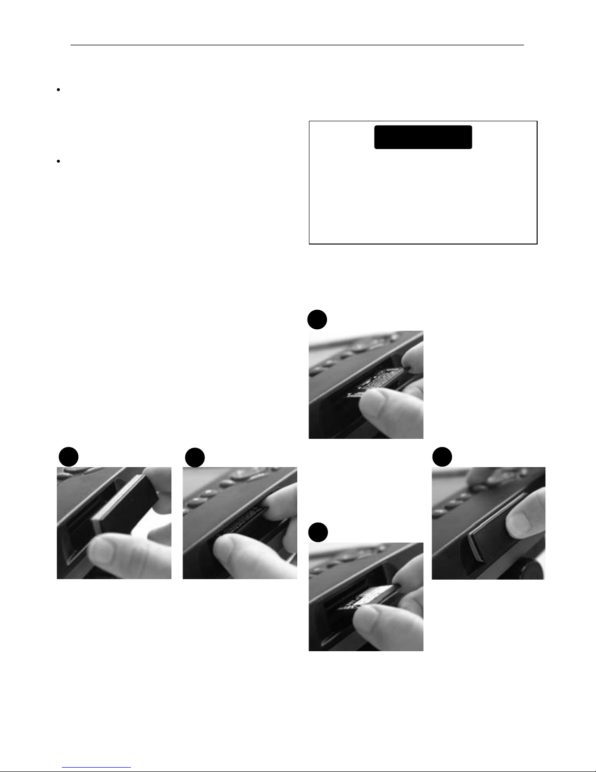
solvents. If a plug-in card gets dirty or wet, clean
it with a damp cloth or mild detergent.
Cover or remove a transom-mounted transducer
when repainting the hull. If painting over a
through hull transducer with antifouling paint,
use only one coat of paint. Remove the previous
coat of antifouling paint by sanding it lightly.
To optimize performance, avoid walking on
or jamming cables and connectors. Keep the
transducer free of weed, paint and debris. Do not
use a high pressure water blast on a speed sensor
paddlewheel as it may damage the bearings.
Push the dust cover over the display when the
Explorer 660 is turned off.
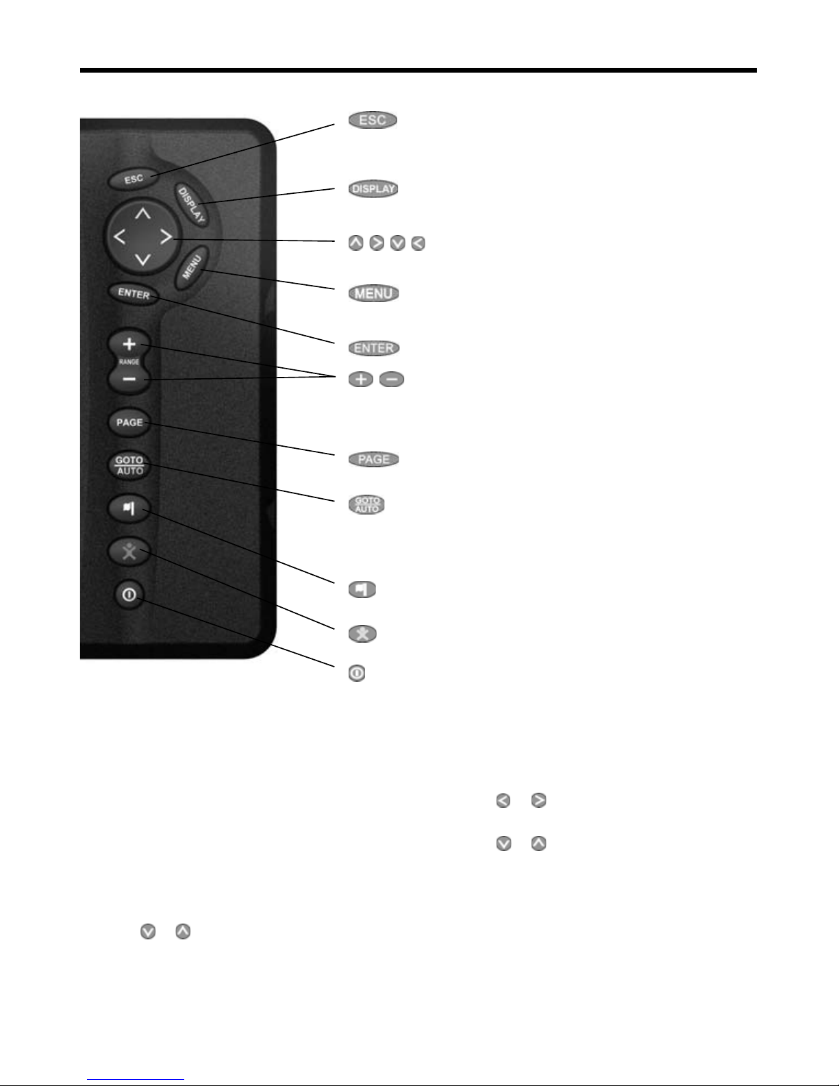
1 Introduction
The Northstar Explorer 660 is a compact, rugged,
highly integrated GPS navigation chartplotter
and sonar fishfinder. It is designed to be easy to
use and has a large, easy to read color display.
Complex navigation or fishfinding functions can
be performed with a few key presses, taking the
hard work out of boating.
This manual describes how to install and operate
the Explorer 660 and gives troubleshooting and
operating tips.
GPS Navigation
The Explorer 660 has a built-in chart of the world,
suitable for route planning and general interest.
To see chart details for a region, plug in a C-MAP™
chart card (an electronic chart).
The Explorer 660 receives GPS position
information from an external GPS antenna and
displays the boat’s position and speed.
The Explorer 660 can navigate to a point or
can navigate along a route. When the boat is
navigating to one of these points, the Explorer
660 displays course information for the
helmsman to follow. The Explorer 660 can control
an autopilot.
Sonar fishfinding
The Explorer 660 has a 50 kHz / 200 kHz dual
frequency sonar transducer and a 600 W RMS
power output to ensure that the Explorer 660
operates effectively in shallow and deep water.
The Explorer 660 can detect the bottom to a
depth of 3300 feet (1000 metres) depending on
the clarity of the water, the ultrasonic frequency
chosen and the type of transducer used.
The Explorer 660 can be used to find fish, to
locate features on the bottom such as reefs or
wrecks and to help recognize favorite fishing
spots from the bottom profile.
The Explorer 660 uses Northstar’s proprietary SBN
technology for sonar processing. Digital adaptive
filter algorithms enhance all returned signals and
filter false returns. Active noise control rejects
interference, which can often be mistaken by
fishfinders for true returns.
Other functions
With an optional fuel kit, the Explorer 660
becomes a sophisticated yet easy to use fuel
computer. Navigation data can be saved to
a plug-in user card so that it can be easily
transferred to another Northstar chartplotter.
The Explorer 660 is part of the Northstar family
of instruments, which includes instruments
for speed, depth, wind and repeaters. These
instruments can be connected together to form
an integrated data system (see section 16-6).
For maximum benefit, please read this manual
carefully before installing and using the unit.
Special terms are explained in Appendix C.

Northstar Explorer 660 Installation and Operation Manual8
1-2 Plug-in cards
The Explorer 660 can use two kinds of plug-in
card:
C-MAP™ chart cards have chart details
required for navigating in a particular region.
When a chart card is plugged in, the extra
details automatically appear on the Explorer
660 chart display.
C-MAP™ user cards are used to store
navigation data. Each user card expands the
Explorer 660 memory and allows the data to
be transferred to another Explorer 660 easily
(see section 13).
Note: The older 5 volt user cards are not
supported.
Changing the plug-in card
The Explorer 660 has two card slots and can use
two plug-in cards at the same time. It does not
matter which slot a card is inserted in.
Turn Explorer 660 off
(see section 2-1).
Remove cover from right
side of case.
12
3a
3b
Pull old card out of
its slot.
Put the old card in
its case.
4
Hold cover correct
way round, push back
in place.
Turn Explorer 660 on
(see section 2-1).
To insert card into
front slot:
Hold card with gold
contacts visible; push
card fully into front slot.
To insert card into
back slot:
Hold card with gold
contacts underneath;
push card fully into
back slot.
Handle plug-in cards carefully. Keep them in
their protective cases when not plugged into
the Explorer 660.
Keep the holders in place in the Explorer 660
at all times to prevent moisture from entering
the card compartment.
CAUTION

Northstar Explorer 660 Installation and Operation Manual 9
1-3 Removing and replacing the display unit
If the display unit is bracket mounted then the
display unit can easily be removed and replaced
for security or protection.
Removing the display unit:
1 Turn the Explorer 660 off (see section 2-1)
2 Push the dust cover over the display unit.
3 Hold the display unit and remove the knobs
from the mounting bracket.
4 Unplug each plug from the back of the
display unit by turning the locking collar
anticlockwise and pulling the plug out.
5 Push the attached dust covers over the
exposed ends of the plugs to protect them.
6 Store the display unit in a dry clean place,
such as the optional Northstar carry bag.
Replacing the display unit
1 Remove the dust covers from the plugs. Plug the
plugs into the back of the display unit:
Match the plug color to the socket color.
Insert each plug and turn the locking collar
clockwise.
Nothing will be damaged if a cable is
plugged into the wrong socket by mistake.
2 Hold the display unit in place in the mounting
bracket. Fit the mounting bracket knobs into
the display unit and do up the knobs loosely.
3 Adjust the tilt and rotation of the display for
best viewing, then hand tighten the knobs
on the mounting bracket. Remove the dust
cover.
Mounting
bracket
Knob
Adjust
tilt, then
tighten
knobs
Adjust
rotation

Northstar Explorer 660 Installation and Operation Manual10
2 Basic Operation
Overview of the keys
Go back to an earlier menu or display. Any changes
are ignored. In chart mode centers chart at boat's
position.
Show a menu of the main Explorer 660 displays. To
go to a display, select it from the menu (see section
2-6).
, , , Cursor keys, to move the cursor or the selection
highlight.
Show a menu of the options for the current display.
Press MENU again to display the Setup menu (see
section 15).
Start an action or accept a change.
, For the chart display: Zoom in or out to display dif-
ferent areas and detail on the chart.
For the sonar display: Change the depth range
displayed.
Switch the display to the next in the favorites list
(see section 2-6-2).
For a navigation display: Start navigating to a point,
waypoint or along a route (see section 3-4).
For sonar display: Select a sonar operating mode
(see section 8-1).
Create an instant waypoint at the boat position (see
section 5-2-1).
Man overboard (MOB, see section 2-3).
Turn Explorer 660 on and off (see section 2-1); adjust
the backlighting (see section 2-2).
In this manual:
Press means to push the key for less than a
second.
Hold means to hold the key down.
The internal beeper beeps when a key is pressed
(to disable or enable the beep, see section 13-1).
Selecting an item in a menu
The Explorer 660 is operated by selecting items
from menus shown on the display.
1 Press or to move the highlight to the
item.
2 Press ENTER to select the item.
Changing a number or word
To change a number or word on the display:
1 Press or to move the highlight to the
digit or letter to change.
Press
or to change the digit or letter.
2 Repeat the above step to change any other
digits or letters.
3 Press ENTER to accept the change.

Northstar Explorer 660 Installation and Operation Manual 11
!
WARNING
2-1 Turning on and off / auto power
Auto power
If the Explorer 660 is wired for auto power (see
section 16-5), then the Explorer 660 automatically
turns on and off with the boat power, and can not
be turned on or off manually.
Turning on manually
If the Explorer 660 is not wired for auto power,
turn the unit on by pressing . If necessary,
adjust the display to be easy to read (see section
2-2).
Turning off manually
If the Explorer 660 is not wired for auto power,
turn the unit off by holding down until the
display turns off.
The MOB feature saves the boat’s position and
then navigates back to this point.
2-3 Man overboard (MOB)
Yes: The Explorer 660 asks if the boat is to go
to the MOB waypoint.
Select:
Yes:To immediately start navigating to
the MOB waypoint.
2-2 Backlight
The display and keys are backlit, with a choice of 16
brightness levels. To change the backlight level:
1. Press briefly to show the display controls.
2. Press to dim or to brighten.
3. Press ENTER to confirm.
Press twice to return to the maximum
backlight setting.
MOB will not work if the Explorer 660 does
not have a GPS fix.
1 Press .
The Explorer 660 stores the boat’s position as
a waypoint called MOB.
2 The Explorer 660 changes to the chart display,
with the MOB waypoint at the centre of the
chart.
The chart zooms in for accurate navigation.
If the chart can not show the required small
scale, the Explorer 660 changes to plotter
mode (a white display with crosshatching and
no chart details, see section 15-2).
3 If the autopilot output (NMEA) is off (see
section 15-10) the Explorer 660 immediately
starts navigating back to the MOB waypoint.
If the autopilot output is on, the Explorer 660
asks if the autopilot is active. Select:
No: The Explorer 660 immediately starts
navigating back to the MOB waypoint.
No: To allow time to disengage the
autopilot; then use Goto to navigate back
to the MOB waypoint (see section 3-4).
To cancel MOB or set another MOB.
1 Press again to display a menu.
2 Select an option from the menu.
Tip: The MOB waypoint remains on the chart
after the MOB has been cancelled. To delete
the MOB waypoint, see section 5-2-5.
This might result in a sudden and dangerous
turn.
!
WARNING

Northstar Explorer 660 Installation and Operation Manual12
2-5 Simulate mode
Simulate mode allows a user to become familiar
with the Explorer 660 off the water. There are two
simulate modes:
In GPS simulation mode, data from the
GPS receiver is ignored and the Explorer
660 generates this data internally. GPS
simulation flashes at the bottom of the
display.
In sonar simulation mode, data from the
sonar transducers is ignored and the Explorer
660 generates this data internally. Sonar
simulation flashes at the bottom of the
display.
Otherwise, the Explorer 660 functions normally.
If both GPS and sonar simulation are selected,
Simulate flashes at the bottom of the display.
To start and stop Simulate mode, see section 15-14.
2-4 Alarms
When the Explorer 660 detects an alarm condition, it displays a warning message on the display, the
internal beeper sounds and any external beepers or lights operate.
Press ESC to clear the alarm. The alarm will sound again if the alarm condition occurs again.
The Explorer 660 has twelve user settable alarms (see section 15-8).
In addition, the Explorer 660 has a fixed alarm for loss of GPS fix.
!
WARNING
Never have Simulate mode on when the
Explorer 660 is navigating on the water.

Northstar Explorer 660 Installation and Operation Manual 13
To show a display, press
DISPLAY, press or to
select the type of display to
show (Chart, Sonar or
Other), press or to
select the display from the list,
then press ENTER.
To return to the chart display,
press ESC.
2-6 The main displays

Northstar Explorer 660 Installation and Operation Manual14
Highway
Fuel
Data
Waypoints
Routes
Satellite
Tides
User card
About

Northstar Explorer 660 Installation and Operation Manual 15
2-6-1 Dual displays
The Explorer 660 can show two displays at once,
for example Chart + sonar or Sonar + highway
(see section 2-6). When two displays are shown at
once, one of the displays, called the active display,
is controlled by the user. For example:
If Chart is the active window, then pressing
MENU will display the options for Chart.
If Sonar is the active window, then pressing
MENU will display the options for Sonar.
The active display has a yellow border.
To change the active display, press
DISPLAY twice:
For example, if Chart + sonar is shown:
If Chart is the active window, then press
DISPLAY twice to make Sonar the active
display.
If Sonar is the active window, then press
DISPLAY twice to make Chart the
active display.
Chart display is active
Yellow border
Yellow border
2-6-2 Favorite displays
The Explorer 660 has a list of commonly used
displays, called favorite displays. There can be up
to six favorite displays and three can be selected
by the user (see section 15-13).
Chart, first
favorite
Press
PAGES
Sonar,
second
favorite
Press
PAGES
Fourth
favorite
display
Press PAGES
Chart+
sonar, third
favorite
Press
PAGES
To change the display to the next favorite, press
PAGES. For example, with five favorites:
DISPLAYDISPLAY
Press
Press
Fifth
favorite
display
Press
PAGES
Sixth
favorite
display
Press
PAGES
DISPLAYDISPLAY
Chart display is not active

Northstar Explorer 660 Installation and Operation Manual16
2-6-3 Data header and compass
The chart, sonar and highway displays can show
data and a compass at the top of the display.
The data header
1 Press MENU and select Data header.
2 To turn the data header off or on:
i Select Data.
ii Select Off or On.
3 To choose the size of the numbers:
i Select Size.
ii Select:
Small: displays three fields per line
and up to four lines.
Medium:displays two fields per line
and up to six lines.
Large:displays same amount of data
as medium but with a larger font.
4 To change the data header:
i Select Data setup.
ii Change a data field:
a Press the cursor keys to highlight the
field.
b Press ENTER to display a menu of the
data that can be shown in the field.
c Select the data to show in the field;
select None to leave the field empty.
iii Repeat the above step to set the other
data fields. Press ESC.
Tip: If less than the maximum number of
lines of data are used, the data will take up
less of the display area.
5 Press ESC to return to the chart display.
The compass
When the boat is navigating to a point, the
compass shows the bearing to the destination
(BRG) in the middle and the boat’s course over
ground (COG), for example here BRG is 4° and
COG is 12°:
Otherwise the compass shows the boat’s COG in
the middle, for example here COG is 12°:
To turn the compass off or on
1 Press MENU and select Data header.
2 Select Compass and select Off or On.
3 Press ESC to return to the display.
BRG (red)
COG
Compass
Data header
A typical display with data and compass
COG

Northstar Explorer 660 Installation and Operation Manual 17
3 Navigation: Chart
3-1 Introduction to navigating
The Explorer 660 has two ways of navigating,
going straight to a point or following a route.
Enter waypoints at points of interest before
starting to navigate (see section 5-2-1).
Tip: Create a waypoint at the start of the trip
to navigate back to.
Goto: Going straight to a point
The Explorer 660 can navigate straight to a
waypoint or to any arbitrary point:
1 Switch to the chart display
(see section 2-6).
2 Start navigating using the GOTO/AUTO key
(see section 3-4).
When the Explorer 660 is navigating, the
chart, data and highway displays show
navigation data. The chart shows:
The boat position .
The destination point marked with
a circle.
The boat’s plotted course to the
destination.
Two CDI lines, parallel to the boat’s
plotted course (see Appendix C, CDI).
If the Explorer 660 is connected to an
autopilot, the Explorer 660 will send data
to the autopilot to steer the boat to the
destination. Start the autopilot.
If the XTE alarm is enabled, an alarm will
sound if the boat deviates too much from its
intended course (to set the XTE alarm, see
section 15-8).
3 If the arrival radius alarm is enabled, then,
when the boat comes within the arrival
radius of the destination, an alarm will sound
to show that the boat has reached the
destination (to set the arrival radius alarm, see
section 15-8).
4 To stop the Goto, see section 3-4.
Following a route
A route is a list of waypoints that the boat can
follow (see section 6).
1 To create waypoints before creating the
route, see section 5-2-1.
2 To create a route, see section 6-2-1.
3 To start the route, see sections 3-4 or 6-3-1.
When the Explorer 660 is navigating,the
chart, data and highway displays show
navigation data. The chart shows:
The boat position .
The waypoint at the end of the current
leg marked with a circle.
The boat’s plotted course along the leg.
Two CDI lines, parallel to the boat’s
plotted course (see Appendix C, CDI).
If the Explorer 660 is connected to an
autopilot, the Explorer 660 will send data
to the autopilot to steer the boat to the
destination. Start the autopilot.
If the XTE alarm is enabled, an alarm will
sound if the boat deviates too much from its
intended course (see section 15-8).
If the arrival radius alarm is enabled, then,
when the boat comes within the arrival radius
of the waypoint at the end of the current leg,
an alarm will sound (to set the arrival radius
alarm, see section 15-8).
4 The Explorer 660 stops navigating to the
waypoint at the end of the current leg and
starts the next leg of the route:
a When the boat comes within 0.025 nm of
the waypoint.
b Or when the boat passes the waypoint.
c Or if the waypoint is skipped (see section
6-3-2).
5 When the boat has reached the final
waypoint, or to stop the boat following
the route at any time, cancel the route (see
section 6-3-3).
The chart display shows the chart, the boat’s position course and navigation data. To show the Chart
display, press ESC until the chart is displayed.

Northstar Explorer 660 Installation and Operation Manual18
The chart. To change
the types of information
displayed, (see section
15-2).
A compass
(see section 2-6-3).
Boat course and CDI lines
(see Appendix C, CDI).
Boat is going to the
waypoint called FISH06.
Data header. To turn the
data off or on or to change
what data is displayed, see
section 2-6-3.
Boat position
(see section 3-2-1).
Boat track
(see section 3-6).
Typical waypoint
(see section 5).
A typical chart display shows:
Distance and bearing of
cursor from boat.
The cursor
(see section 3-2-1).
3-2 Chart display
Sea
Land
3-2-1 Chart modes
The Chart has two modes, centre on boat mode
and cursor mode. These are explained below.
Centre on boat mode
To switch to centre on boat mode in the chart
display, press ESC. The boat is at the centre of
the chart. As the boat moves through the water,
the chart automatically scrolls to keep the boat
in the centre of the chart. The cursor (see below)
is turned off.
Cursor mode
The keys , , and are called cursor keys.
To switch to cursor mode in the chart display,
hold down a cursor key. The cursor appears
and moves away from the boat:
Press the key which points in the direction
that the cursor will move, for example press
to move the cursor down.
Press midway between two of the cursor keys
to make the cursor move diagonally.
Hold a cursor key down to make the cursor
move continuously across the display.
In Cursor mode:
The distance (+DST) and bearing (+BRG) of
the cursor from the boat are displayed at the
bottom, left corner of the display.
The chart does not scroll as the boat moves.
If the cursor reaches the edge of the display,
the chart will scroll.
For example, hold down
to move the
cursor to the right side of the display and the
chart will scroll to the left.

Northstar Explorer 660 Installation and Operation Manual 19
!
WARNING
3-2-2 Latitude and longitude
Latitude and longitude can be displayed in the
data header. Normally the position is the boat’s
position, and the latitude and longitude has a
boat symbol to show this:
If the cursor has been moved in the last ten
seconds, then the position is the cursor’s position,
and the latitude and longitude has a cursor
symbol to show this:
3-2-5 Find nearby places
To find and display nearby places of interest:
1 To see places near the boat’s position, press
ESC to switch to centre on boat mode. To see
places near a different point, move the cursor
to that point on the chart.
2 Press MENU and select Find.
3 Select the type of place. There are three
types, Ports, Port services and Tide stations.
For a Port service, select the type of service to
find.
4 A list of places is displayed. If there are more
places than will fit on the display, press
or
to scroll up or down a page at a time.
To search for a port by name:
i Press MENU and select Find.
ii Enter some or all of the letters of the port
name. Press ENTER.
5 Select the place and press ENTER. The chart
display changes to show the selected place in
the middle of the display.
6 To see stored information about the selected
place, press MENU and select Chart info
(see section 3-2-5). To display a tide chart for a
selected tide station, select Tide height
from the chart info.
Minutes, to 3 decimal places
(about 2 m (6 ft) resolution)
Degrees
36°29.637' S
175°09.165' E
Latitude
Longitude
+36°29.684' S
+175°09.201' E
When reading the boat position, make sure
the position is not the cursor position.
3-2-3 Chart scale
Press to zoom in and display a smaller area of
the chart in more detail. Press
to zoom out
and display a bigger area in less detail.
The chart scale can be displayed (e.g. scale
= 8 nm, see below). The scale is the vertical
distance across the currently visible chart area.
For example if the scale is 8 nm then a portion
of chart eight nautical miles high is currently
displayed.
3-2-4 Chart symbols and information
The chart will show symbols, such as waypoints
and chart symbols (for example buoys, beacons,
wrecks and marinas). When the cursor is placed
over a symbol for at least two seconds, a data
window appears at the bottom left of the display
with information about the symbol.
To see stored information about a point on the
chart (for example, a chart symbol):
1 Move the cursor to that point on the chart.
2 Press MENU and select Chart info.
3 A menu of objects is displayed:
i Select an object to display.
ii Press ESC to return to the menu. Select
other objects.
iii Finally, press ESC to return to the chart.

Northstar Explorer 660 Installation and Operation Manual20
3-3 Distance and bearing calculator
The distance and bearing calculator can plot a
course of one or several legs and to show the
bearing and length of each leg, as well as the
total distance along the course. The completed
course can be converted into a route.
To use the distance and bearing calculator:
1 Press
ESC until the chart display is displayed.
Press MENU and select Distance.
2 Move the cursor to the start of the first leg. It
does not matter if this point is a waypoint or
not. Press ENTER.
3 To add a leg to the course, move the cursor
to the end of the leg. It does not matter if this
point is a waypoint or not. The display shows
the bearing and length of the leg, as well
as the total distance along the course. Press
ENTER.
3-4 GOTO: Navigating to a point or along a route
The GOTO/AUTO key is a shortcut to start
navigating to a point on the chart, to a waypoint
or along a route.
Starting to navigate
Navigating to a point on the chart
1 Press ESC until the chart display is displayed.
2 Move the cursor to the destination point.
3 Press GOTO/AUTO and select
Goto cursor.
Navigating to a waypoint
See section 5-3-1.
Navigating along a route
See section 6-3-1.
4 To remove the last leg from the course, press
MENU and select Remove.
5 Repeat the above two steps to enter the
whole course.
6 To save the new course as a route, press
MENU and select Save. This also saves any
new points on the course as new waypoints,
with default names. If necessary, edit the
route later (see section 6-2-2) and edit any
new waypoints later (see section 5-2-3).
7 Finally, press ESC to return to the
chart display.
Note: See section 15-7 for Log functions.
Cancelling navigation
Cancelling navigating to a point on the chart
or to a waypoint
1 Press
ESC until the chart display is displayed.
2 Press
GOTO/AUTO and select
Cancel goto.
Cancelling navigating along a route
See section 6-3-3.
!
WARNING
Make sure the course does not pass over land
or dangerous waters.
The Explorer 660 navigates to the destination as
described in section 3-1.
Table of contents
Other NorthStar Fish Finder manuals