Page 3
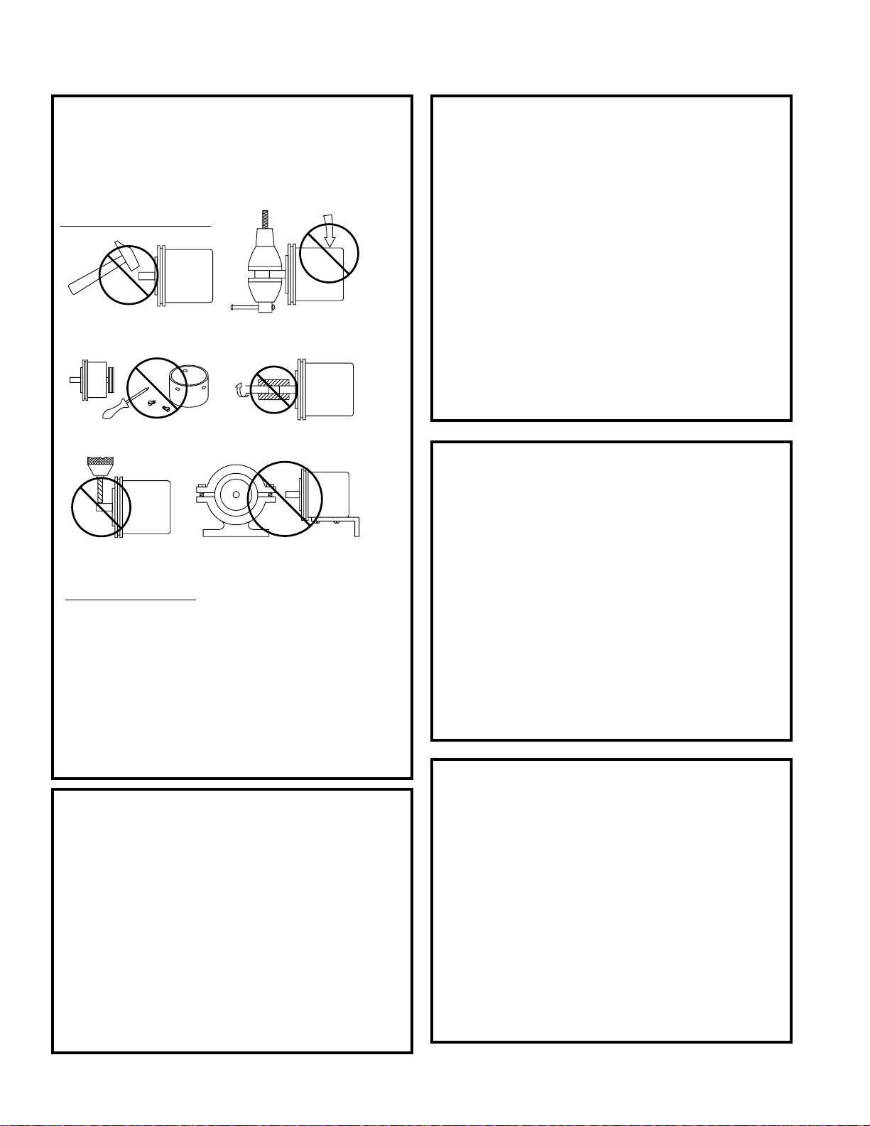
IMPORTANT INSTALLATION INFORMATION
FREQUENTLY ASKED QUESTIONS
There are additional colored wires which are not
referred to in the Electrical Specifications table.
What do I do with them?
Do not connect them to the receiving device.Any
unused encoder signal wires must be individually
insulated and tied back. They should NEVER be in
contact with common, power sources, or other
output signal lines.
The encoder is correctly connected to the
receiving device per the Electrical Specifications
table and the receiving device’s terminal strip
label; however, it’s counting in the wrong
direction. What’s wrong?
In order to reverse the counting direction, the output
signal connections must be switched. If the encoder
has a single ended output, swap A and B. If the
encoder has a differential line driver, swap A and –
A.
I’ve connected the encoder and it doesn’t work (
No Outputs). What can I do?
Many encoders have internal protection circuits
which shut down the encoder to prevent damage if
the input power is not correct or the outputs are
overloaded. Check the following: Input Voltage (is it
too high?); Input Polarity (is it reversed?); and
Output Wiring (are they wired properly?).
I’ve read and followed the technical manual and
these guidelines and the encoder still doesn’t
work properly. Help!?
Calm down - help is at your fingertips! Simply pick up
the phone and dial our Applications Engineering
Department at 1-800-234-8731 (US & Canada) or
847-662-2666 from 8:00 AM to 4:45 PM (Central
time) Monday - Friday. One of our engineers will
gladly help you solve the problem.
FEATURES (cont.)
Common should always be connected to the negative
(-) side of DC power.
All encoders have at least one output signal (A);
however, it is common for encoders to have three
signals A, B, Z (may also be referred to as C, X, or
index). The outputs should each be connected to the
receiving device at the appropriate terminal. NOTE:
Never connect A, B, or Z to the + or - side of DC
power.
When encoders have a differential line driver, there
are two signals for each of the outputs. Each signal (A,
B and Z) has a compliment or inverse (–
A, –
B and –
Z
referred to as A not, B not, and Z not). The signal and
its compliment (i.e. A and –
A) are separate outputs.
Connect each output to a separate input.
NOTE: Never connect these signals together or to
the + or - side of DC power. Never connect differ-
ential signals to the same input.
CONNECTIONS
Obviously not all receiving devices are the same.
However, connecting your encoder to one, no matter
what type or brand it may be, is not difficult.As
discussed in the previous section, all encoders have
certain electrical features. Each of these features/
functions are identified in the encoder’s Electrical
Connections table along with its corresponding pin
and wire color. Each wire specified in the table must
be connected to the receiving device.
Determining where to connect each wire is as easy as
following the Electrical Connections table and match-
ing each wire to the proper terminal on the receiving
device. In general, no matter what type of receiving
device you are using, the terminal strip is marked,
indicating the proper location for each function/wire.
These markings may either be numbers or text labels
identifying functions. If they are numbers, the receiv-
ing device’s manual should define what function
corresponds to each number.
Since receiving devices are made by various manu-
facturers, not all text labels/references are the same.
There are various ways to identify each function.
Following are a few examples:
Note: Encoders that
feature differential
outputs will also have
complementary outputs
referenced as
–
A, –
B, –
Z, (A-not, B-not,
Z-not).
Typical
Encoder
Power
Common
Signal A
Signal B
Index
Referred to as:
Vcc; +Power
DC Power
12VDC
Referred to as:
Comm
–Power
–DC
Referred to as:
Input A
A+
Sig. A
Referred to as:
Input B
B+
Sig. B
Referred to as:
Marker
Z
Sig. C