Northwest Marine Technology Multishot User manual

Handheld Multishot Tag Injector
Instruction Manual
Northwest Marine Technology, Inc.
4003 Airport Road, Anacortes, WA, 98221, USA
+1 (360) 764-8850 offic[email protected]
www.nmt.us

Need help? Call +1 (360) 764-8850 or email offic[email protected] v4.2 Jan 2021| Page 3
Contents
1 Introduction .............................................................................................................................5
1.1 How the Multishot works ............................................................................................................. 5
1.2 Overview of CWT tagging .............................................................................................................. 6
1.3 A few things to consider before tagging ....................................................................................... 6
2 Getting Started .........................................................................................................................7
2.1 Keep it clean! ................................................................................................................................ 7
2.2 Needles ......................................................................................................................................... 7
2.2.1 Seating the needle ....................................................................................................................... 8
2.3 Loading tag wire ............................................................................................................................ 9
2.4 Selecting the tag length .............................................................................................................. 10
2.5 Head mold and needle clamping nut with support tube ............................................................ 11
2.6 Needle penetration depth .......................................................................................................... 11
2.7 Push wire function and adjustment ............................................................................................ 12
2.8 The Cutter ................................................................................................................................... 12
2.8.1 Changing the cutting edge .......................................................................................................... 13
2.9 The counter ................................................................................................................................. 13
2.9.1 Resetting the counter ................................................................................................................. 13
3 Troubleshooting ..................................................................................................................... 14
3.1 Maintenance ............................................................................................................................... 15
3.1.1 Needle care ............................................................................................................................... 15
3.2 Cleaning protocol ........................................................................................................................ 15
3.2.1 Disinfection ............................................................................................................................... 15

Need help? Call +1 (360) 764-8850 or email offic[email protected] v4.2 Jan 2021| Page 4
3.2.2 Cleaning equipment and supplies ................................................................................................ 16
3.2.3 Hourly cleaning .......................................................................................................................... 16
3.2.4 Daily cleaning ............................................................................................................................ 16
3.2.5 Complete cleaning ..................................................................................................................... 17
4 Service .................................................................................................................................... 18
4.1 Disassembly ................................................................................................................................. 18
4.2 Reassembly ................................................................................................................................. 21
5 Parts Reference ...................................................................................................................... 27
5.1 Multishot body ............................................................................................................................ 27
5.2 Supply body ................................................................................................................................. 29
6 Tool Kit Contents .................................................................................................................... 31

Need help? Call +1 (360) 764-8850 or email offic[email protected] v4.2 Jan 2021| Page 5
1 Introduction
Northwest Marine Technology (NMT) designed the Multishot to be a small, portable, handheld “field”
tool for injecting Coded Wire Tags (CWT) into small batches of fish or into very large specimens (e.g.,
brood stock, endangered species, live trapped smolts, and adult paddlefish). A T-Wand or V-Detector is
typically used with the Multishot to verify the presence of a CWT in an animal.
1.1 How the Multishot works
A complete injection cycle for the Multishot has the following steps (Figure 1):
1. The coded wire is advanced by depressing the wire advance lever. A ratcheting mechanism
determines the tag length by moving the wire forward a fixed distance.
2. The tag is cut by pressing the cut lever.
3. The tag is magnetized and advanced to a point just short of the tip of the needle by moving the push
rod knob forward until a slight resistance is felt (about 40 mm).
4. The needle is inserted into the specimen.
5. The push rod is moved forward the remaining distance (about 8 mm)
to inject the tag into the specimen. The needle is removed from the
specimen.
6. The push rod is fully retracted to release the cut lever to the “up”
position. The Multishot is ready to repeat the cycle.
When operating the
Multishot, use brisk
motion to properly
engage the springs and
levers.
Figure 1: How the Multishot works.
Push rod knob
Wire advance
lever
Cut lever

Need help? Call +1 (360) 764-8850 or email offic[email protected] v4.2 Jan 2021| Page 6
1.2 Overview of CWT tagging
Mark recapture experiments using the Coded Wire Tag (CWT) consist first of implanting tags in the
specimens, verifying implantation and releasing the specimens. The second stage involves recovering
and screening the specimens for tags and reading the tags. Tag implantation sites influence which
verification and recovery procedures are used. Please refer to our CWT Project Manual
(https://www.nmt.us/wp-content/uploads/2017/11/Coded-Wire-Tag-Project-Manual-Nov-2017.pdf) for
detailed information about using CWT.
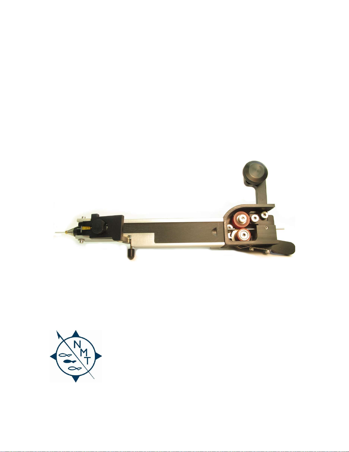
Coded Wire Tags are supplied as a spool of wire. The Multishot cuts a tag from the spool, magnetizes
the tag, and injects it into the specimen. The operator then verifies that the specimen contains a Coded
Wire Tag using one of the detectors made by NMT.
Upon recovery of the specimen, CWTs are located using one of the available detectors. CWTs are
removed from the specimen and then the tag code is read under magnification (25X or higher).
1.3 A few things to consider before tagging
Tag Type: Coded Wire Tags are available in several formats. These include different tag sizes and
coding options. The tag type you choose will depend upon specimen size, data requirements and
recovery methods.
Tag Implantation Site: The area or “target” where the tag will be implanted can vary for different
applications. While salmon and trout have traditionally been tagged in the snout, other species are
tagged in the cheek, adipose eyelid, jaw, scalp, nape, leg, etc. Choosing a suitable implantation site
is critical to tag retention, specimen health, and tag recovery.
Tag Insertion Technique: Some tagging is done with the aid of head molds to precisely position the
specimen during tagging. It is very important to use a head mold of the proper size and shape for
the particular specimen, otherwise tag retention may be poor. NMT offers a variety of head molds
for different species of fish ranging in size from 0.25 grams to 225 grams. If you are tagging a species
for which a head mold is not available, or if you wish to make your own molds, contact NMT about
the head mold fabrication kit and instructional video. Tagging can also be done without the use of
these fixtures if specimen size varies widely, the implantation site is large, or a suitable positioning
fixture is not practical. A needle support tube is available for this type of tagging.
Tag Recovery: How the tags will be recovered must be considered during program design. Specimen
size at the time of recovery, tag location, tag type, recovery site and detector technology can all
influence the method and success of tag recovery.

Need help? Call +1 (360) 764-8850 or email offic[email protected] v4.2 Jan 2021| Page 7
2 Getting Started
2.1 Keep it clean!
The Multishot MUST BE CLEAN to operate properly. The Multishot uses specially manufactured coded
wire that is only 0.25 mm in diameter. This wire advances through a tiny hole in a cutter, the tag is cut,
and then the tag is pushed through a needle with an inside diameter of 0.3 mm. The tag is pushed by the
push wire, also only 0.25 mm diameter. There is little clearance for dirt and the Multishot will not work
smoothly if fish slime builds up in the needle, in the cutter, or on the push wire.
The Multishot should be rinsed with fresh water regularly during use to remove fish slime and other dirt.
It is also advised that after each hour of use the following sequence should be followed: The unit should
be submersed in a bucket of fresh water; the cut lever depressed and held down; and then the push rod
advanced and retracted a dozen times (this sequence requires only a few seconds and is well worth the
effort). This action works the push wire through the cutter and the needle causing a surging of fresh
water through the system to dissolve any fish slime. A small amount of liquid detergent will help the
cleaning. If you find that the push rod is not advancing smoothly it is likely one of two problems—either
the needle is not seated properly or the unit needs cleaning!
Detailed cleaning procedures are described in section 3.2.
2.2 Needles
The Multishot uses a 1.55 inch (3.94 cm)
needle. This needle will accommodate the use
of head molds or a needle clamping nut with
support tube (see Figure 6: needle clamping nut
with support tube, see also discussion of head
molds). Proper needle selection is important to
the success of the tagging operation.
The Multishot needle is available as either
“etched” or “non-etched” (figure 2). The non-
etched needle has a constant outside diameter
(0.0225 inch, 0.57 mm) from its base all the
way to the beginning of the beveled tip. The etched needle is necked down to a smaller outside
diameter (0.0185 inch, 0.47 mm) beginning approximately 0.3 inches (0.76 cm) from the beginning of
the bevel. The etched needle makes a smaller injection hole in the fish and has been very successful
with head molds for Pacific Salmon. The etched needle will not work as well (i.e., it has a greater
likelihood of bending) with fish of tougher tissue such as steelhead, nor will it work as well with most
“body” tagging such as the cheeks of smallmouth bass, the scutes of sturgeon, or the rostrum of
paddlefish. For this type of tagging, the non-etched needle in a needle support tube is often the better
combination for penetration and tag placement.
Figure 2: Etched and
n
on
-
etched
needle
s
Non
-
etched
Etched

Need help? Call +1 (360) 764-8850 or email offic[email protected] v4.2 Jan 2021| Page 8
2.2.1 Seating the needle
The needle must be properly seated in the cutter (figure 3). An improperly seated needle may be
ejected when the push wire is advanced, or the push wire may bend when trying to advance it through
the needle. Either of these symptoms suggest that the needle should be examined for proper seating.
Figure
3: Seating the
n
eedle
Needle Clamping Nut
Needle
Nylon Ball
Magnetizer
Magnet
Magnetizer Holder
Base
To seat the needle (assuming the needle clamping nut and needle are removed from the Multishot):
1. Position the nylon ball approximately one third of the length down the needle from the tip (the
beveled end).
2. Slide the base of the needle (the funnel shaped end) into the magnetizer until it meets resistance;
the needle will contact the cutter.
3. While pushing gently, rotate the needle until you feel the funnel end of the needle slide into the
cutter.
4. Now slide the needle clamping nut over the needle and thread it into the magnetizer; you may need
to push the nylon ball into the magnetizer a short distance with your fingernail to provide room for
the initial thread of the needle clamping nut.
5. Finger-tighten the needle clamping nut and then use the one-eighth inch hex wrench to tighten the
nut until it is snug - approximately a quarter turn.
6. Loosen the needle clamping nut a quarter turn and then re-tighten one quarter turn. Repeat the
loosen/re-tighten step a total of three to four times. This step ensures that the needle is properly
seated against the cutter without binding the cutter.

Need help? Call +1 (360) 764-8850 or email offic[email protected] v4.2 Jan 2021| Page 9
2.3 Loading tag wire
Figure 4 shows the tag supply body, wire guide,
and spool arm. See section 5 for parts
schematics.
The tag supply body should be attached to the
Multishot body (if it is not, refer to Reassembly
item 21).
1. Remove the protective cover from the tag
supply body by sliding it back. Unscrew the
spool retainer, place the plastic tag supply
spool onto the stud, and replace the spool
retainer.
2. Rotate the spool support arm counter
clockwise to place the roller pressure arm in
the “off” position. This will separate the drive
and idler rollers.
3. Threading the tag wire is easier if you
straighten out any curl in the tag wire by
running it between your thumb and forefinger. Thread the end of the tag wire into the wire guide,
between the drive and idler rollers and into the feed tube that protrudes from the Multishot body.
Use the tweezers to guide the tag wire if necessary.
4. Feed the tag wire by hand into the Multishot as far as it will go.
5. To determine if the tag wire has been fully inserted in the cutter, press
down gently on the cut lever (figure 1). A slight resistance will be felt if
the tag wire is in the cutter. Lower the spool support arm to apply
pressure to the two rollers. Replace the protective cover.
6. Cut the first tag (which will be a non-standard length and should be
discarded) by depressing the cut lever, and then eject the tag by
advancing the push rod all the way forward.
7. Retract the push rod all the way so that the cut lever returns to the up
position. The Multishot is now ready to start a new injection cycle.
The
cut lever
must be
up when the tag wire
is fed into the
Multishot.
Never advance the
push rod if it is
jammed. See section
3, Troubleshooting, if
this occurs.
Idler roller
Coded Wire Tag
spool
Spool
retainer
Drive roller
Roller pressure
arm
Wire guide
Wire advance
lever
Wire guide set
screw
Spool
support
arm
Figure 4: The tag supply body

Need help? Call +1 (360) 764-8850 or email offic[email protected] v4.2 Jan 2021| Page 10
2.4 Selecting the tag length
The Multishot can inject standard length (1.1 mm),
one and a half length (1.65 mm) or double length (2.2
mm) tags. It will not inject the 0.5 mm half length tag.
Standard and double length tags use the standard
ratchet, and are selected by adjusting the wire
advance lever stop set screw to control the throw
(range) of the wire advance lever (Figure 5). See
Section 5 for parts schematics.
Standard length tags are cut when the screw is in,
and double length tags are cut when the screw is out.
Do not take the screw all the way out! If the screw is
removed too far then the wire advance lever will
swing out of the bottom of the wire supply body.
Cutting 1.5 length tags requires replacing the
standard rachet with the special ratchet. The special
ratchet, which has fewer teeth than the standard
ratchet, is optional.
Alignment bar
Counter reset button
Wire advance lever
s
top
s
et
s
crew
Figure 5: The Multishot
counter and stop set screw
To inject
double length tags, the
s
top
set
screw does not have to be removed, simply
retract the standard length screw.
-or-
If the Mulitshot is set to cut standard length
tags and you wish to cut a double length tag
without changing the wire advance lever
stop set screw, press the wire advance lever
twice before pressing the cut lever. Note,
however, if you are using a counter, this
approach will increment the counter by two.
Similarly, if the special ratchet is installed to
cut 1 1/2 length tags, then pressing the wire
advance lever twice will generate a triple
length tag.

Need help? Call +1 (360) 764-8850 or email offic[email protected] v4.2 Jan 2021| Page 11
2.5 Head mold and needle clamping nut with support tube
The needle clamping nut with support tube is a modified needle clamping
nut that is supplied with the Multishot (figure 6). The needle clamping nut
with support tube is designed to stabilize the base of the needle to prevent
the needle from bending when tagging. Use of the needle clamping nut
with support tube is encouraged except when using a head mold.
The needle clamping nut with support tube can also be used to gage the
depth of needle penetration by applying a piece of tape around the base of the support, or slipping a
piece of plastic tubing of the proper length over the support.
Head molds are most often used for snout
tagging. NMT supplies a variety of sizes and
shapes. Custom head molds can also be
constructed. A head mold holder (supplied with
the Mulitshot) is slipped over the needle and
onto the front of the magnetizer (figure 7: head
mold holder). It is secured by tightening the set
screw at the base of the head mold holder. A
head mold is then inserted and secured by
tightening the set screw at the front of the
head mold holder.
2.6 Needle penetration depth
The depth to which the needle penetrates the specimen is controlled in one of two ways.
1. With the freehand method (using the Multishot without a head mold) the operator determines
needle penetration by how far the needle is pushed into the specimen. It is useful to mark the
needle with a depth stop of some type (tape, tubing, etc.) so you can repeat the tag position for
each specimen.
2. When using a head mold, needle penetration can be adjusted by setting the distance that the
needle protrudes from the head mold when the head mold slide is fully depressed. The head
mold is adjusted in or out by loosening the head mold set screw and moving the head mold to
the desired position, then tightening the set screw.
Head mold slide
Head
m
old
s
prings
Head mold set screw
Head mold
attachment
set screw
Head
m
old
holder
Figure 7: Head mold holder
Figure
6: Needle
c
lamping
nut with support tube

Need help? Call +1 (360) 764-8850 or email offic[email protected] v4.2 Jan 2021| Page 12
2.7 Push wire function and adjustment
Tag placement depth refers to the position of the tag with
respect to the tip of the needle. The push wire advances the tag
to the tip of the needle. The only way to adjust tag placement
depth relative to the tip of the needle is to adjust the
advancement of the push wire.
The set screw at the center rear of the push wire slide (figure 8
and section 5) is used to adjust the advancement of the push wire. Remove the tag supply body and
body cover (see Disassembly Instructions 2 and 5). Reach the adjusting set screw by pushing down the
cut lever and moving the push rod all the way forward. Using the 0.050 inch hex ball-driver, rotate the
set screw counter-clock wise if you want the cut tag to be injected further out the needle; rotate the set
screw clockwise if you want to have the tag further back into the needle. The approximate position of
the cut tag can be determined by observing how the location of the push wire tip changes as the screw
is rotated.
2.8 The Cutter
The cutter (figure 9) is a precision device to cut the tags cleanly from
the spool of tag wire. The cutter is also the most expensive part of
the Multishot to replace. It should be cared for accordingly. With
proper handling the cutter should provide excellent service. It is not
uncommon for a cutter to yield over 50,000 cuts.
The
push wire
assembly is
manufactured to a fixed length.
DO NOT attempt to change the
length of the push wire by
cutting or filing the push wire.
Push rod knob
Push rod
Push wire slide
Feed tube
Set screw for
push wire
Figure 8: Multishot Injector body
Locking
lip
Retaining
collar
Cutter
sleeve
Cutter
pin
Figure
9
: The cutter

Need help? Call +1 (360) 764-8850 or email offic[email protected] v4.2 Jan 2021| Page 13
2.8.1 Changing the cutting edge
The cutter pin has two cut edges available. To change the cut edge refer to instruction 10 in section 4.2,
Reassembly.
2.9 The counter
The electronic counter is always on; there is no off switch. The estimated battery life is at least 3 years.
Return the counter to NMT if it no longer works.
2.9.1 Resetting the counter
The counter increments by one each time the wire advance lever is depressed. Depress the white dot
with a dull implement to reset the counter (figure 5). The counter will not decrement.
Keep
the cutter
c
lean
! Clean the
cutter
periodicall
y during use, and after each use. Do not let the
cutter set for hours or overnight without proper cleaning. If you intend to leave the Multishot laying
around for several hours between uses, soak it in a bucket of fresh water to prevent fish slime from
drying on the cutter, in the needle, and on the push wire.

Need help? Call +1 (360) 764-8850 or email offic[email protected] v4.2 Jan 2021| Page 14
3 Troubleshooting
PROBLEM
POSSIBLE CAUSES
SOLUTION
N
eedle
pulls out of
Multishot
Improper seating of
needle
Tighten
needle
n
ut or reseat the
needle.
N
eedle
breaks
Dull
needle
into tough tissue;
improper leverage from Multishot
Use a sharp
needle
in a
needle
support
tube, and do not pry up, down or
sideways with Multishot while the
needle is in the fish
P
ush wire
jams or
sticky
N
eedle
not seated properly;
needle not coned properly;
Multishot is dirty; burrs on the
push wire
Reseat
needle
; fix cone on
needle
;
clean Multishot; use sharpening stone
to remove burrs from end of push wire
P
ush rod
jammed or
sticky
P
ush rod
improperly secured to
push wire slide; Multishot dirty;
push wire jammed
See
reassembly item 5 for securing rod
to slide; clean Multishot; see above for
jammed push wire
Cu
tter
not cutting
smoothly
Multishot
dirty;
cutter
dull or
damaged; push wire too long; cut
lever damaged; cut lever spring or
cut lever alignment pin screws
missing
Clean
Multishot
;
replace
cutter
; adjust
push wire; replace cut lever, cut lever
spring, or cut lever adjustment screws
Cutting short tags
D
rive roller
s worn
Replace worn
drive roller
s
Counter not working
Dead battery;
c
ounter damaged
Return to NMT
Wire
advance lever
sticks
Dirty
Multishot
;
a
dvance
l
ever
pull
spring damaged
Clean
Multishot
,
partic
ularly the wire
supply body; replace advance lever pull
spring

Need help? Call +1 (360) 764-8850 or email offic[email protected] v4.2 Jan 2021| Page 15
3.1 Maintenance
3.1.1 Needle care
A bent or dull needle must be replaced. Inspect the beveled end
of the needle to see that it is smooth and sharp. A dull needle
makes penetration difficult and may tend to push the specimen
away, causing shallow implantation of the tag. Multishot needles
have several bevels and can not be sharpened.
When inspecting or replacing a needle, examine the slight
“funnel” at the back end of the needle with the magnifying loupe
(figure 10). The funnel helps guide the tag into the needle and
can be damaged if the tag wire jams in the Multishot. The funnel
can be reshaped using the needle reamer and the Arkansas stone
in the tool kit. Insert the point of the reamer into the funnel and
turn it a few times with light pressure to restore the proper
shape. The rim of the funnel can be smoothed with the
sharpening stone to remove the external flare caused by reaming
and/or jams. Inspect the funnel end of the needle to make
certain that the last 5 mm is straight.
3.2 Cleaning protocol
3.2.1 Disinfection
The possibility of spreading fish diseases between culture facilities and watersheds is of concern to both
our customers and Northwest Marine Technology. Although we are unaware of a case of coded wire
tagging equipment moved between locations as having served as a "vector" in spreading a disease, the
consequences of such occurrences call for stringent preventative measures. Disinfection procedures
should also be implemented between groups of fish within a facility when signs of disease exist. Tagging
should not be conducted during a severe outbreak of disease.
Chlorine solutions are recommended for use as disinfectants on tagging equipment. Commonly used
source of chlorine are calcium hypochlorite ("HTH") and solutions of sodium hypochlorite ("bleach").
Household bleach comes in a concentration of about five percent so that to achieve the desired
concentration one would dilute an ounce of bleach in each two gallons of water (a ratio of 1:250).
Stronger solutions may be available at fish rearing facilities so that a lesser proportion of material would
be required to achieve the desired concentration (200 ppm) of active ingredient. An alternative is a
solution of chlorine dioxide (sold under various trade names including Oxine [CH20, International]). This
material appears to be far less corrosive and less hazardous than the previously mentioned bleach and
HTH. To reduce corrosion, alcohol (70 - 90%) is recommended as the disinfectant and cleaning agent for
the interior mechanisms of NMT equipment.
Calcium hypochlorite and sodium hypochlorite solutions are highly toxic to fish but can be neutralized by
adding sodium thiosulfate or sodium sulfite to the solution. As a "rule of thumb", if a five percent
Figure
1
0
: Needle
f
unnels

Need help? Call +1 (360) 764-8850 or email offic[email protected] v4.2 Jan 2021| Page 16
solution of these chlorine compounds is used as a disinfectant, they can be neutralized by adding an
equal weight of either chemical. For example, one ounce of 5% bleach added to two gallons of water
would be neutralized by one ounce (dry weight) of either sodium sulfite or sodium thiosulfate. If the
chlorine solution is stronger, the weight of the neutralizing agent should proportionately increase. As an
added precaution, "neutralized" disinfectant should not be poured directly into water containing fish.
Before using any disinfectant, read and understand the Material Safety Data Sheets (MSDS) for each
product.
3.2.2 Cleaning equipment and supplies
In addition to the disinfectants indicated above, the following equipment and supplies are
recommended for cleaning your Multishot:
Two spray bottles for dispensing alcohol
and chlorine solutions
Tap (pathogen free) water
50 ml syringe with 20 gauge needle
Wiping sponge/cloth
Cotton tipped applicators made of wood
(available from medical supply stores)
Cotton balls
2-3” of blank/excess coded wire
Multishot tool kit
Multishot instruction manual
Paper towels
An open container for soaking parts
Material Safety Data Sheets
Rubber gloves
Eye protection
Particle masks or respirator
3.2.3 Hourly cleaning
Each hour, or more often if necessary, the Multishot should be submersed in a bucket of fresh water to
remove fish slime and other dirt. It is best to hold the unit under water, depress the cut lever, and then
slide the push rod back and forth a dozen times to surge water through the needle and cutter. This
practice only takes a few seconds and clearly helps assure a smooth operation of the Multishot.
3.2.4 Daily cleaning
This simplified cleaning procedure should be performed at the end of each day’s tagging. Use a chlorine
solution and rinse with alcohol. Use cotton swabs or other non-abrasive cleaning tools.
1. Disassemble the Multishot following disassembly steps 1, 2 and 4 thru 11 in section 4.1. See section
5 for parts schematic.
Cleaning:
The Multishot has many precision components which can become stuck or otherwise
inoperable if not cleaned regularly during use and at the end of each day’s tagging and before being
stored. Careful cleaning will enhance performance and greatly extend the life of the unit so please
take cleaning seriously.

Need help? Call +1 (360) 764-8850 or email offic[email protected] v4.2 Jan 2021| Page 17
2. Use the chlorine solution to clean the needle, cutter pin, inside of the cutter sleeve and any exposed
Multishot surfaces that are dirty.
3. Use a piece of tag wire dipped in alcohol to clean the inside of the needle, holes in cutter pin and
holes in the cutter sleeve.
4. If you are using the head mold holder, it can be cleaned without disassembly by removing it from
the Multishot and soaking it in the chlorine solution overnight (do not use alcohol on the head
mold).
5. Dry all surfaces before reassembling or storing, especially the cutter sleeve and cutter pin to prevent
corrosion.
3.2.5 Complete cleaning
This procedure is recommended if disease is a concern, and should also be performed before the
Multishot is stored for an extended period of time. Again, use fresh water, a disinfectant, and non-
abrasive cleaning tools.
1. Completely disassemble the Multishot following steps 1 thru 17 in section 4.1 and clean all parts in
chlorine solution.
2. Use a piece of tag wire dipped in alcohol to clean the inside of the needle, holes in the cutter pin,
holes in the cutter sleeve and the inside of the feed tube.
3. Use a piece of tag wire to clean the inside of the feed tube and nesting needle in the groove on the
bottom of the feed tube.
4. Use alcohol and cotton swabs to clean the exterior of all other components.
5. If you are using the head mold holder it can be cleaned without disassembly by removing it from the
Multishot and soaking it in alcohol overnight. Soak the head mold in the chlorine solution NOT in
alcohol.
6. Dry all surfaces before reassembling or storing, especially the cutter sleeve and cutter pin to prevent
corrosion. A thin film of silicone FEL-PRO LUBRI-SIL #51360 grease (or equivalent) is recommended
on the following parts: alignment bar, cut lever alignment pin, detent assembly, and the pull spring
screws.
7. Keep the needle protector in place during storage and transit to protect the needle and prevent
injury.

Need help? Call +1 (360) 764-8850 or email offic[email protected] v4.2 Jan 2021| Page 18
4 Service
Although the Multishot requires little maintenance if properly cleaned and cared for, certain
components of the unit will need service with regular use. The following is a recommended service
schedule (which will vary with each unit depending on the cleaning, maintenance, and handling by the
owner):
After each 30,000 tag injections the drive roller, idler roller, wire advance lever spring, pull spring,
push wire and needle clamping nut should be inspected for wear, and likely replaced.
After 50,000 injections the cutter, push rod assembly, and pull spring should be inspected for wear
and likely replaced. This service should be performed at NMT by one of our trained service
technicians.
After 3 years the Counter’s battery should be replaced. This service must be performed at NMT by
one of our trained service technicians.
4.1 Disassembly
1. Remove the tag wire. Release the pressure on the drive roller by moving the spool support arm up
to the “off” position. Grasp the tag wire and pull it out the rear of the Multishot. Remove the tag
supply spool from the spool retainer.
2. Remove the tag supply body from the Multishot body. The tag supply body clips in a slot at the rear
of the Multishot body. To separate the two, remove the alignment bar, being careful to lift it straight
out to avoid binding of the two pins (you may have to initially pry the alignment bar loose with a
thin implement). Once the alignment bar is removed, hold the tag supply body in one hand and the
Multishot body in the other and pull them straight apart so you do not break the feed tube, which
extends into the tag supply body from the Multishot body. The two pieces fit together fairly tightly
so some resistance will be felt.
3. Remove the drive roller assembly:
i. Remove the tag supply body cover and relax the idler roller (off position of the spool
support arm).
ii. Remove the ratchet pull spring, which is attached with two screws to the bottom of the wire
advance lever.
iii. Back out the wire advance lever stop set screw and swing the wire advance lever down
(figure 5).
iv. Loosen the wire guide set screw and slide the wire guide away from the drive roller
assembly.
v. Remove idler shoulder screw and idler roller.
vi. Remove the drive roller shoulder screw and the drive roller assembly will lift out.
4. If you are using the optional head mold holder remove it by loosening the head mold attachment set
screw (figure 7) with the .050” wrench and slide it off the magnetizer assembly.
5. Remove the needle. Use the 1/8” wrench to remove the needle clamping nut (figure 3). Pull the
needle and its nylon ball out of the magnetizer assembly.

Need help? Call +1 (360) 764-8850 or email offic[email protected] v4.2 Jan 2021| Page 19
6. The body cover is held in slots in the Multishot body. Remove the cover by sliding it back.
7. Remove the cut lever spring retainer and cut lever spring. Use your finger to apply slight upward
pressure on the cut lever. Press down on cut lever spring retainer and turn it 90 degrees in either
direction so it disengages from the cut lever, then lift out the cut lever spring retainer and cut lever
spring. The spring and retainer normally come out together.
8. Remove the cut lever (figure 12). Use your finger to apply slight upward pressure on the cut lever. It
may be necessary to retract the push rod so that the cut lever can be moved to its “up” position.
Using two 5/64” hex head drivers, remove the cut lever alignment pin.
Figure 12: Cut
lever removal
sequence.
O
nly one side of
the alignment
pin cap screw
will come free
from the
Multishot. The
other side is
permanently
secured to the
alignment pin.
1
Feed tube
2
3
Push rod
Cut lever spring
retainer and spring
Cut lever
alignment pin
Cut lever
1
Hex head driver
Cut lever
alignment pin

Need help? Call +1 (360) 764-8850 or email offic[email protected] v4.2 Jan 2021| Page 20
9. Remove the cut lever by lifting the back of it to clear the Multishot body, then pulling it back to slide
it off the dowel pin.
10. Remove the magnetizer assembly. Use the 3/32” wrench to remove the two main assembly screws
from the bottom of the Multishot body (figure 13). Pull the magnetizer straight out away from the
Multishot. The Magnetizer assembly is one piece. Do not try to separate the metal from the black
plastic.
11. Remove the push rod from the push wire slide (figure 8). Pull the push rod back all the way and hold
in place. Note the position of the groove in the forward end of the detent (horizontal to the left).
The push rod must fit into this groove when it retracts and is important on reassembly. Use the
3/16” nut wrench to remove the nut and split washer that secures the push rod. Hold push wire
slide in place and slide push rod forward so it is clear of the push wire slide. The push rod is held in
the Multishot body by the push rod spring and e-clip. Remove the e-clip and slide the push rod and
spring out of the Multishot body.
12. With the push wire slide fully retracted, use the 3/32” ball-driver to slide the base forward, away
from the feed support tube. When the base is fully disengaged from the feed support tube, lift up,
taking the base and cutter out together (figure 13).
Figure 13: Magnetizer and base removal.
13. Separate the cutter from the base. Rotate the cutter pin 90 degrees, in the direction which allows
the flat spot on the cutter pin retaining collar to clear the locking lip of the cutter sleeve (figure 9).
The cutter pin can then be pulled up and out of the cutter sleeve.
14. Remove the feed tube support, feed tube and push wire slide. These parts are removed from the
Multishot body at the same time by lifting up on feed tube support and then pulling it forward so
the back of the feed tube comes out of the hole in the back of the Multishot body. Do not separate
the feed tube support from the feed tube.
1
Magnetizer
assembly
Main
assembly
screws
Base
2
Table of contents
Other Northwest Marine Technology Laboratory Equipment manuals
Popular Laboratory Equipment manuals by other brands

Lumencor
Lumencor SOLA SM instruction manual

Omni
Omni THq user manual

Merlin Instrument Company
Merlin Instrument Company Merlin MicroShot instruction manual

NLB
NLB Artecno STERILIZE quick start guide

Amnis
Amnis ImageStream Mark-II Quick start guides

Tektronix
Tektronix Keithley 2380-500-30 Performance Verification Manual