Northwest Marine Technology MKIV User manual

Northwest Marine Technology, Inc.
4003 Airport Road, Anacortes, WA 98221, USA
Phone: +1 (360) 764-8850 Email: office@nmt.us
www.nmt.us
MKIV Coded Wire Tag Injector
Instruction Manual


Page 3 Need help? Call +1 (360) 764-8850 or email of[email protected]
Table of Contents
1. Introduction ................................................................................................................... 7
2. Setup.............................................................................................................................. 9
2.1 Contents Checklist......................................................................................................................... 9
2.2 Assembly ....................................................................................................................................... 9
3. Quick Start ................................................................................................................... 11
4. Getting Ready to Tag .................................................................................................... 15
4.1 Needle Selection .........................................................................................................................15
4.2 Needle Positioning Jig Selection .................................................................................................16
4.3 Tag Length................................................................................................................................... 17
4.4 Common Menu Settings ............................................................................................................. 19
4.4.1 Using a head mold and 2.5 inch needle.................................................................................................19
4.4.2 Using a needle support tube and a 3.5 inch needle ..............................................................................19
4.4.3 Using a needle support tube and a 3.5 inch needle (alternate) ............................................................19
4.5 Needle Penetration..................................................................................................................... 19
4.6 Tag Placement Depth.................................................................................................................. 20
4.7 Final Check .................................................................................................................................. 21
5. Configuration ............................................................................................................... 23
5.1 Keyboard ..................................................................................................................................... 23
5.1.1 Key: [TOTAL] ..........................................................................................................................................24
5.1.2 Key: [BATCH] ..........................................................................................................................................24
5.1.3 Key: [CLeaR] ...........................................................................................................................................24
5.1.4 Key: [BATTery] .......................................................................................................................................25
5.1.5 Key: [LOAD]............................................................................................................................................25
5.1.6 Key: [SHOW] ..........................................................................................................................................26
5.1.7 Key: [*] ...................................................................................................................................................26
5.1.8 Key: [-10], [+10], [-1], [+1]......................................................................................................................27
5.1.9 Key: [TAG] ..............................................................................................................................................27
5.1.10 Key: [ESCape].....................................................................................................................................27
5.1.11 Key: [OK]............................................................................................................................................28
5.1.12 Key: [STEP].........................................................................................................................................28
5.1.13 Key: [ADJustment] .............................................................................................................................29
5.2 Adjustment Menu ....................................................................................................................... 30
Item: SETUP...................................................................................................................................................................... 30
Item: TAG LENgth ............................................................................................................................................................. 30
Item: WIRE........................................................................................................................................................................ 31
Item: QCD THRESHold ...................................................................................................................................................... 31
Item: STOP........................................................................................................................................................................ 31
Item: NEEDLE MOVe......................................................................................................................................................... 32
Item: MIN. TIME ............................................................................................................................................................... 33
Item: QCD BEEP................................................................................................................................................................ 33
Item: QCD DELAY.............................................................................................................................................................. 33
Item: CUT EDGE................................................................................................................................................................ 34
Item: TAG CREDIT............................................................................................................................................................. 35
Item: US-EURopean.......................................................................................................................................................... 35
6. Quality Control Device (QCD)........................................................................................ 37

Page 4 GEV v 4.0 Feb 2021
6.1 Overview .....................................................................................................................................37
6.2 General Assembly (Mechanical and Water Jet Versions) ........................................................... 39
6.3 Mechanical Diverter Gate Assembly...........................................................................................41
6.4 Separator (Water) Jet Adjustments ............................................................................................43
7. Maintenance ................................................................................................................ 47
7.1 Injector Disassembly ...................................................................................................................47
7.2 Injector Assembly........................................................................................................................ 50
7.2.1 Needle Carrier Installation.....................................................................................................................50
7.2.2 Needle Installation.................................................................................................................................52
7.3 Parts Inspection ..........................................................................................................................54
7.3.1 Needle Inspection and Maintenance.....................................................................................................54
7.3.2 Cutter.....................................................................................................................................................55
Cutter Inspection.............................................................................................................................................................. 57
7.3.3 Needle Carrier........................................................................................................................................58
7.3.4 Drive Rollers...........................................................................................................................................59
7.3.5 Touch Switch..........................................................................................................................................59
7.3.6 QCD Solenoid Valve (Water jet version QCD only) ................................................................................60
Removal and Installation.................................................................................................................................................. 60
7.3.7 Solenoid Valve Cleaning.........................................................................................................................60
7.3.8 QCD Filter Assembly (Both QCD versions) .............................................................................................62
Filter Cleaning................................................................................................................................................................... 62
7.4 Cleaning and Disinfection ........................................................................................................... 63
7.4.1 Equipment and Supplies ........................................................................................................................64
7.4.2 Injector...................................................................................................................................................64
7.4.3 Quality Control Device (QCD) ................................................................................................................65
8. System Messages.......................................................................................................... 67
BAD DRIVE XY......................................................................................................................................................67
BAD MEMORY .....................................................................................................................................................67
CHECK ALL ADJ ....................................................................................................................................................67
CHECK NEXT TAG.................................................................................................................................................67
CUTTER STUCK ....................................................................................................................................................67
INT ERROR...........................................................................................................................................................67
NEEDLE STUCK ....................................................................................................................................................67
NO QCD OK .........................................................................................................................................................67
NO WIRE OR STUCK ............................................................................................................................................67
POWER LOW .......................................................................................................................................................67
READY VX.X .........................................................................................................................................................68
*RELOAD WIRE....................................................................................................................................................68
WEAK MEMORY ..................................................................................................................................................68
9. Troubleshooting the MKIV Injector ............................................................................... 69
9.1 Injector displays “NO WIRE OR STUCK” ......................................................................................69
9.2 Injector displays “INT ERROR”....................................................................................................70
9.3 Injector displays “CHK NEXT TAG” ..............................................................................................70
9.4 Tag wire unthreads and backs out when leaving LOAD mode. .................................................. 70
9.5 Tag length varies. ........................................................................................................................ 71
9.6 Injector indicates “CUTTER STUCK” ............................................................................................71
9.7 A tag is not ejected from the needle. ......................................................................................... 72
9.8 Injector cycles continuously........................................................................................................72

Page 5 Need help? Call +1 (360) 764-8850 or email of[email protected]
9.9 Injector indicates “NEEDLE STUCK” ............................................................................................73
9.9.1 Needle stuck on the return stroke.........................................................................................................73
9.9.2 Needle stuck on the forward stroke ......................................................................................................73
9.10 The tag wire jams........................................................................................................................ 74
9.11 Injector indicates "POWER LOW" ............................................................................................... 77
9.12 Nothing happens when Injector is turned on. ............................................................................ 77
9.13 The display reads “* RELOAD WIRE”...........................................................................................78
10. Troubleshooting the QCD .......................................................................................... 79
10.1 The QCD is not detecting tags..................................................................................................... 79
10.2 The QCD detects a tag but tagged fish is not diverted. .............................................................. 79
10.3 The QCD is sorting fish to the opposite side from before. .........................................................79
10.4 The QCD diverter is working, but fish are not sorted properly. ................................................. 80
10.5 The QCD activates erratically, even with no tagged fish present............................................... 81
10.6 Water leaks from the QCD’s filter housing. ................................................................................ 82
10.7 QCD reject count is negative.......................................................................................................82
11. Appendix A: Tool Kit Components ............................................................................. 83
12. Appendix B: Main-Plate Parts List .............................................................................. 85
13. Appendix C: Adjustment Menu.................................................................................. 87
14. Appendix D: Setups ................................................................................................... 89
15. Appendix E: Size Conversion Table for Salmonids....................................................... 91
16. Appendix F: Spare Parts and Accessories ................................................................... 93
17. Equipment Specifications .......................................................................................... 95
17.1 MKIV Tag Injector........................................................................................................................ 95
17.2 Quality Control Device ................................................................................................................95
17.3 Power Supply .............................................................................................................................. 95
18. Index......................................................................................................................... 97

Page 7 Need help? Call +1 (360) 764-8850 or email of[email protected]
1. Introduction
Northwest Marine Technology (NMT) designs
and manufactures Coded Wire Tags and their
associated injection and detection equipment.
The Coded Wire Tag (CWT) identification
system provides an accurate and versatile
method for assessing and researching natural
and hatchery reared fish populations. Coded
Wire Tags have been implanted in hundreds of
different marine and freshwater species.
Reliability of the equipment and data allow for
application in many areas of fisheries research
and management.
The MKIV Tag Injector is designed to give years
of reliable performance. Please read and
understand the operating and maintenance
instructions so you can obtain the maximum
service from this product. The most up-to-date
version of this manual is available on our
website (www.nmt.us; NMT User Manuals).
The MKIV Injector comes in various
configurations:
1. MKIV Tag Injector only (a V-detector or
T-Wand for quality control is
recommended).
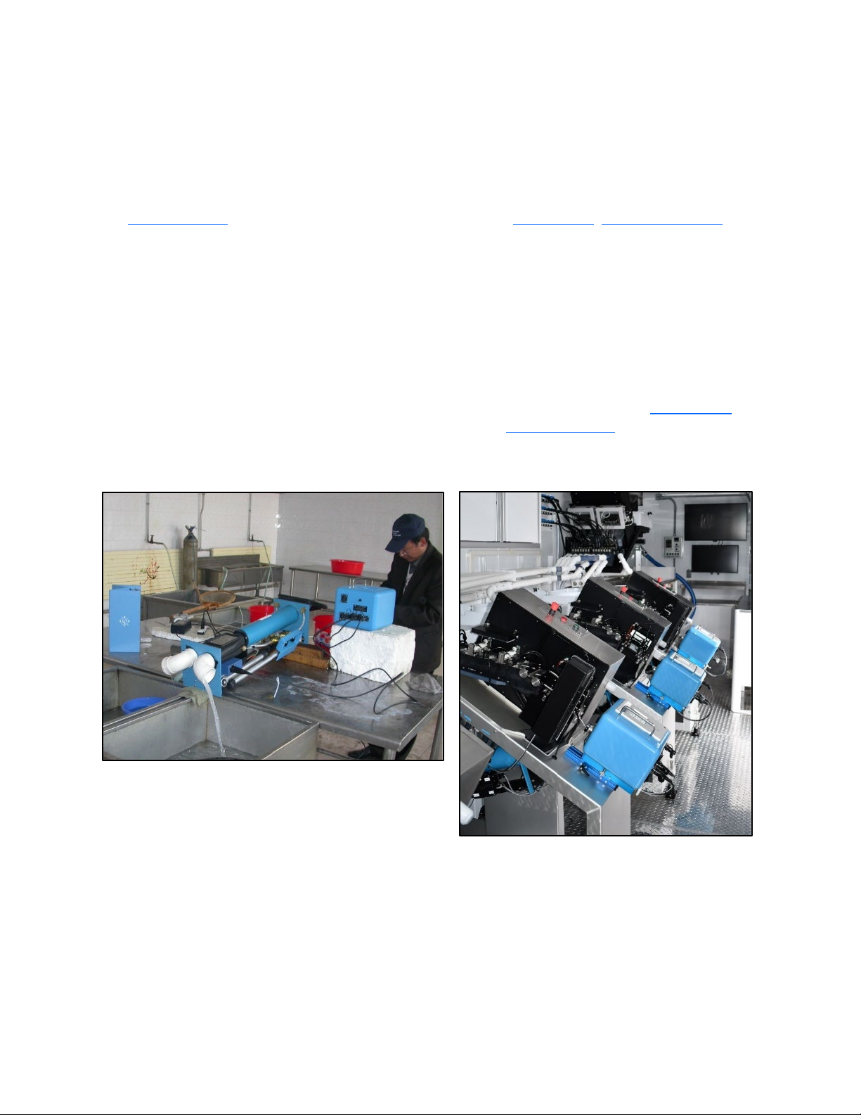
2. MKIV Tag Injector with a Quality
Control Device (QCD), Figure 1.
3. MKIV Tag Injector in an AutoFish trailer
(Figure 1)- refer to the AutoFish SCT
Operator Manual).
Figure 1: MKIV with QCD for manual tagging (left) and installed in AutoFish System for automated
tagging.

Page 9 Need help? Call +1 (360) 764-8850 or email of[email protected]
2. Setup
2.1 Contents Checklist
A MKIV Tag Injector is shipped with the
following items in a transit case:
•MKIV Tag Injector
•Power Supply
•Touch Switch or Foot Switch
•3 non-custom head molds
•3,000 tag spool of test wire
•Tool Kit (see Appendix A: Tool Kit
Components)
•Instruction Manual
A MKIV Tagging Unit includes these additional
items:
•Quality Control Device (QCD)
•Interconnect Cable
•Funnel
•Quick disconnect with a water filter.
Remove all items from the boxes and make sure
nothing has been left in the packing materials.
2.2 Assembly
1. Place the Injector on a stable,
flat surface near the power
source. The tagging equipment
operates on 12-28 volts DC
(about 50 watts). The Injector
comes with a power supply
which converts 110-240 volts AC
to 24 volts DC. Plug the power
supply into a grounded AC
power outlet.
2. Alternate DC power sources
such as a 12 V automobile
battery can also be used when
AC power isn’t available.
Adapters for use with alternate
power sources are available
from NMT.
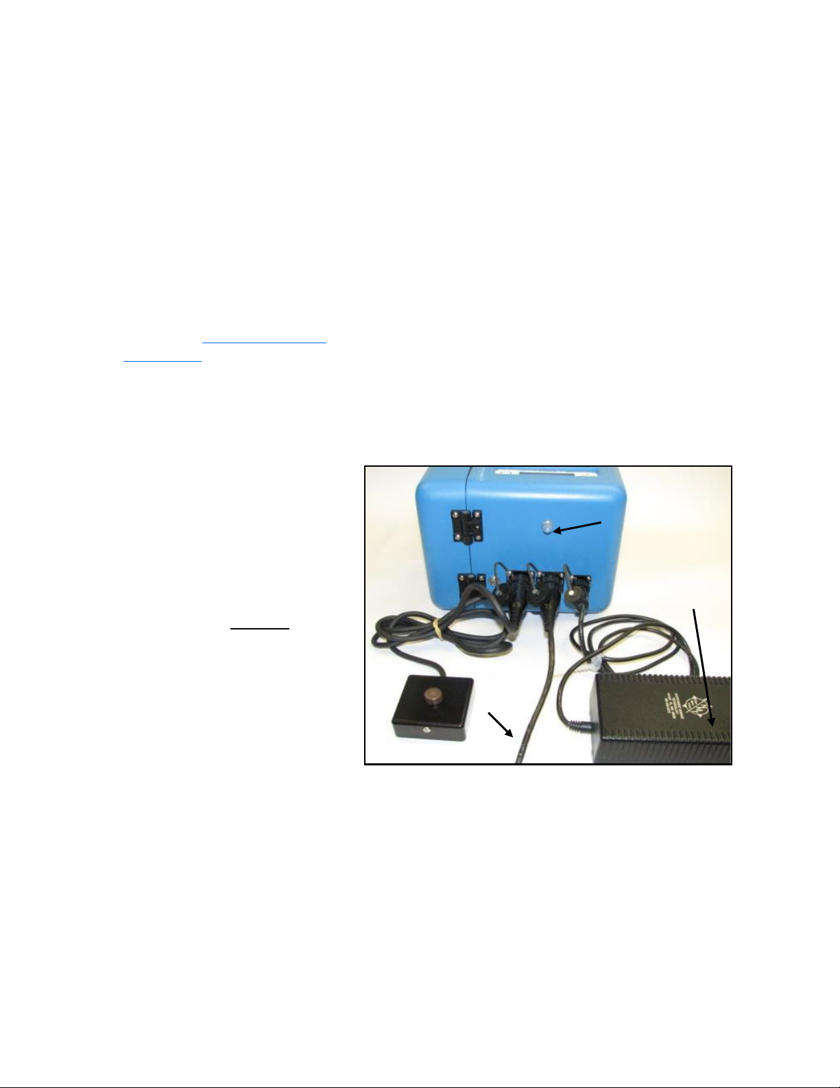
3. Connect the cable from the power supply to the 4-pin connector on the back of the Injector.
Touch switch
QCD
interconnect
cable
Power supply
On/off switch and
circuit breaker
Figure
2: Back view of the MKIV Injector

Page 10 GEV v 4.0 Feb 2021
4. Attach the cable from your touch switch or foot
switch to either of the two large connectors on the
back of the Injector.
5.
6. If you are using a QCD, connect it to the other large
connector on the back of the injector (
7. Figure 3). See (Quality Control Device (QCD), page 37)
for more information about setting up your QCD.
Figure 3: Cable connections for a mechanical gate QCD.
MKIV Injector
QCD Detection Head
Separator
Gate Actuator
Gate Box
QCD Electronics Box
24 VDC
Power
Supply
110-220
VAC
Touch Switch
The two large connectors
on the back of the Injector
are interchangeable. Keep
the protective caps closed
on any unused
connector(s).
WARNING! To avoid
damaging the
electronics
,
do not connect the QCD
while the Injector is
turned on.

Page 11 Need help? Call +1 (360) 764-8850 or email of[email protected]
3. Quick Start
After the equipment is assembled, follow these steps for initial testing and familiarization. The steps
below confirm that the equipment is operating and ready for the remaining adjustments. Completing
these steps does not mean that everything is ready for tagging.
Step 1: Open the latch on the front of
the Injector (Figure 4) and swing
the door open.
Figure 5 shows the parts on the Injector main plate with the door open.
Figure
5: MKIV Injector main plate.
Spool retainer
Actuator arm
Drive roller latch
Idler roller arm
Pressure
spring
Shoulder
bolt
Entry wire guide
E-clip
Magnetizer
Idler roller
Drive
roller
Cutter block
wire guide
Cutter
Needle carrier
clamp
Needle carrier
Head
mold
base
LED
Door
lh
Head
mold base
Blue
tag
LED
Figure
4:
Front of MKIV Injector,
AutoFish
version left, standard
version, right.
Page 12 GEV v 4.0 Feb 2021
Step 2: Turn on system power by pressing the rubber-covered On/Off button on the back of the Injector
(Figure 2). When the Injector is turned on, a self-test sequence will take place and the display
will show a "READY VX.X" message where “X.X” is the firmware version number.
The Injector has a built-in circuit breaker and protective fuse. If the circuit breaker is tripped, the
Injector will shut off. The circuit breaker will automatically reset after about one minute. If the
circuit breaker does not reset, the internal protective fuse is most likely blown and the Injector
must be returned to NMT for servicing.
If a QCD is not connected, or if the self-test detects a problem with the QCD, the display will
show the message "NO QCD OK?". If you see this message and the QCD is connected, check to
make sure the QCD Interconnect Cable is properly installed.
If you are not using a QCD, press any key on the keyboard to confirm this status and clear the
message.
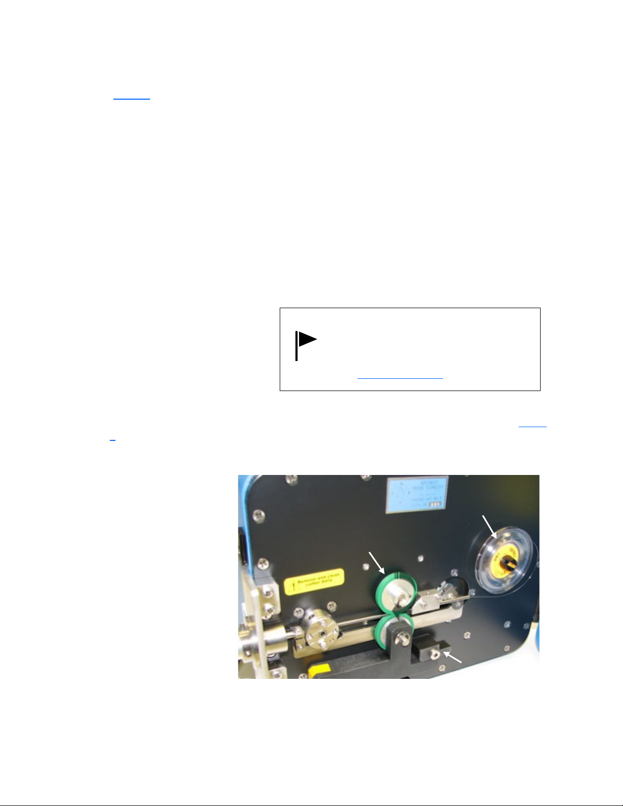
Step 3: The Injector is shipped with a spool
of test wire installed. If there is not
a spool of wire on the machine,
install one on the spool retainer
before proceeding.
Step 4: Locate the idler roller arm and move the drive roller latch so that the rollers are engaged (Figure
6).
Step 5: Load the tag-wire by
pressing [LOAD] (page 25)
on the keyboard. The
display will show “LOAD
100" and the drive rollers
can be rotated easily by
hand. The Injector may
make a hissing sound
when in the LOAD
position. This is normal.
tag wire
drive roller
Engage the
drive roller
latch
rotate
Figure
6: Loading tag wire.
The MKIV Injector ships with a 2.5 inch
needle installed which is protected by a
head mold base. If a needle is not
installed or a 3.5 inch needle is required,
see Needle Installation, page 54.

Page 13 Need help? Call +1 (360) 764-8850 or email of[email protected]
Step 6: Insert the tag-wire into the entry wire guide and push it forward until it reaches the drive rollers.
Rotate the top roller clockwise by hand to feed the wire into the cutter block wire guide (Figure
6). Continue turning the top roller until the tag wire extends slightly beyond the tip of the
needle.
Step 7: Press the [OK] key. The Injector will retract and cut the tag wire. Cycle the Injector once by
pressing either the Touch Switch button, the [TAG] key, or the blue tag switch on the front of the
Injector if equipped (Figure 4, page 11). Any of these three switches will cycle the Injector. The first
piece of wire ejected will be longer than a standard tag. Cycle the Injector a few more times to see how
it operates and confirm the Injector is making the proper length tags. Each cycle will produce one tag.
If a QCD is attached, the red error light and tone will be activated as determined by the tag
credit value (page 35). This indicates that tagged specimens are not being detected by the
QCD, and is normal for this sequence.

Page 15 Need help? Call +1 (360) 764-8850 or email [email protected]
4. Getting Ready to Tag
Before tagging, please read NMT’s Coded Wire Tag Project Manual, available at www.nmt.us . It
provides a comprehensive overview of coded wire tagging projects and discusses appropriate setups for
a variety of species and environments.
The following MKIV Tag Injector adjustments need to be made or checked before tagging:
•Needle selection (page 15)
•Needle Positioning Jig Selection (for example a head mold) (page 16)
•Tag Length (page 17)
•Common Menu Settings (page 19)
•Needle Penetration (page 19)
•Tag Placement Depth (page 20)
If you are using a Quality Control Device (QCD) you will also check or adjust:
•Water flow and General Assembly (Mechanical and Water Jet Versions) (page 39)
•Separator (Water) Jet Adjustments (water jet version only) (page 43)
or
•Mechanical Diverter Gate Assembly (mechanical gate version only) (page 41)
•Item: QCD DELAY (page 33)
•Item: QCD THRESHold (page 31)
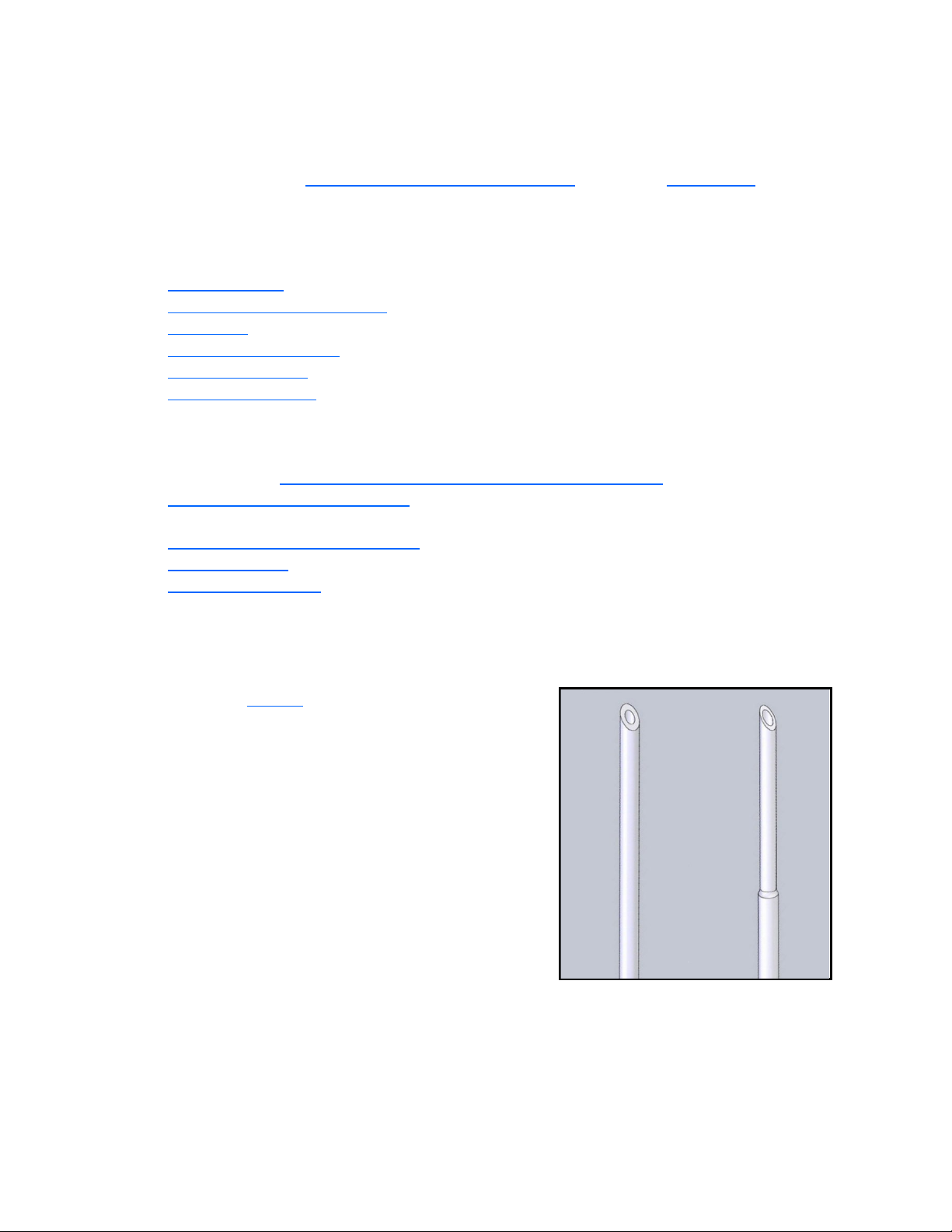
4.1 Needle Selection
Four needle styles (Figure 7) are offered for the MKIV Tag
Injector:
•2.5 inch (63.5 mm), etched or non-etched
•3.5 inch (89 mm), etched or non-etched
Non-etched needles do not have a reduced outside diameter
near their tip, making them better suited for larger animals or
tagging into tougher tissue because of their added strength.
Etched needles have a reduced outside diameter near the tip,
making them better suited for smaller animals, where a
smaller incision is required or for tagging into soft tissue. The
trade-off with etched needles is reduced strength in the tip.
Non-etched
Etched
Figure
7: Needle styles

Page 16 GEV v 4.0 Feb 2021
4.2 Needle Positioning Jig Selection
The most common type of positioning jig used with a MKIV Tag Injector is the head mold (Figure 8). NMT
sells head molds for a wide variety of size and species fish (see Table 1). A custom head-mold kit is also
available from NMT to allow the end user to create unique head molds.
Table 1: NMT stock head mold sizes.
Species
Head Mold Size (fish/lb); CMS=Closed Mouth Style
Coho/Chinook
5, 10, 15, 20, 30, 45, 65, 90, 120, 200, 300 (CMS), 550, 1100
Steelhead
(Rainbow)
2(5), 3(8), 5(12), 7(18), 11(27), 20(50), 36(90), 80(200)
Pink
2000 (CMS)
Atlantic Salmon
7, 9, 11, 15, 25, 30, 50, 100, 120
Lake Trout
5, 8, 12, 18, 27, 50, 90
Chum
700
Head Mold Size (length in mm);
CMS=Closed Mouth Style
Sockeye
60 (CMS), 90
Walleye
55, 65, 125
Mullet
60-70, 70-80, 100, 120, 140
Paddlefish
Not size designated, but for ~ 6 inch fish
Tagging can be done without a positioning jig. Many fishes,
crustaceans, and other animals have tag locations which
don’t need or aren’t conducive to, the use of a positioning
jig. The operator would manually impale the specimen on a
non-moving needle (see Item: NEEDLE MOVe, page 32) and
then inject the tag. Without a jig, is still desirable to have
some depth control so that you know how much of the
needle has penetrated the specimen. The needle support
tube (available as an accessory) makes a good depth stop.
Figure 8: Positioning jigs – tagging with a head mold (top)
and with a needle support tube (bottom).
Page 17 Need help? Call +1 (360) 764-8850 or email [email protected]
4.3 Tag Length
There are two ways to set the tag length of the Injector:
1) Under Item: SETUP (page 30) in the
Adjustment menu (ADJ), select
Standard (otherwise known as single
length tags), Half, 1 ½, or Double.
2) Choose the appropriate tag length in
the Adjustment menu under the
option Item: TAG LENgth (page 30).
Using the TagLength option will
automatically display Special if other
options, for example Needle Move, are
changed in the Adjustment menu. You can
also store 2 different adjustment settings
using Custom1 and Custom2 (page 30).
If the MKIV Tag Injector is set up to cut
tags SHORTER than that specified on the
spool, then the code(s) will be
unreadable.
Page 18 GEV v 4.0 Feb 2021
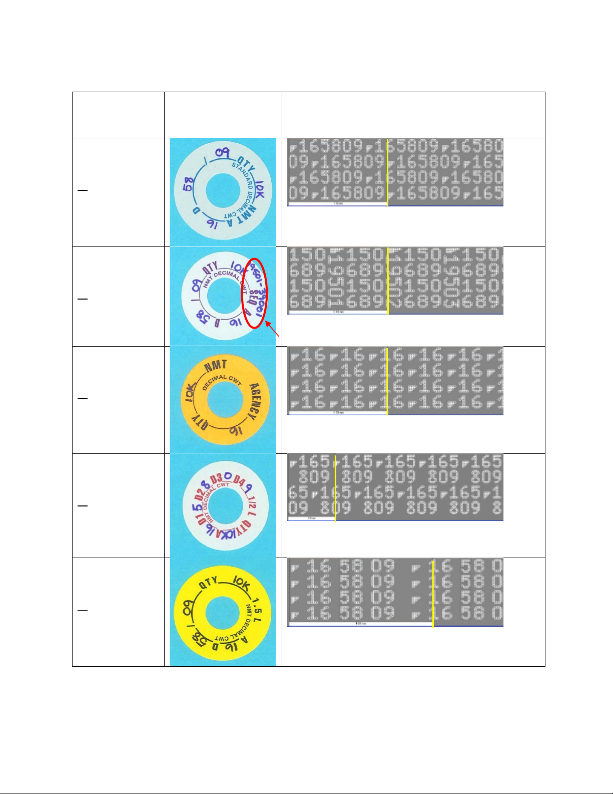
Table 2: Coded Wire Tag formats
CWT format and
MKIV Injector
setting
Spool label
Layout: If a 2 mm piece of wire were unrolled and
magnified, it would look like this. The yellow bars show
where tags of each format might be cut by the injector.
Standard CWT:
TAG LEN [SGL]
or
SETUP
[STANDARD]
Sequential CWT:
TAG LEN [SGL]
or
SETUP
[STANDARD]
Sequence numbers
Agency CWT:
TAG LEN [SGL]
or
SETUP
[STANDARD]
½ Length CWT:
TAG LEN[1/2]
or
SETUP[HALF]
1 ½ Length CWT:
TAG LEN[1 1/2]
or
SETUP[1 1/2]

Page 19 Need help? Call +1 (360) 764-8850 or email [email protected]
4.4 Common Menu Settings
4.4.1 Using a head mold and 2.5 inch needle
•Item: SETUP [STANDARD/HALF/1 1/2] (page 30)
•Key: [SHOW] [96] (page 26)
4.4.2 Using a needle support tube and a 3.5 inch needle
•Item: SETUP [SPECIAL/CUSTOM 1/CUSTOM 2] (page 30)
•Item: NEEDLE MOVe [NO] (page 32)
•Item: STOP [1] (page 31)
•Key: [SHOW] [171] (page 26)
4.4.3 Using a needle support tube and a 3.5 inch needle (alternate)
This setup using Stop 2 and a small amount of Needle Move is recommended over no
Needle Move (section 4.4.2) and Stop 1 if poor tag retention is an issue.
•Item: SETUP [SPECIAL/CUSTOM 1/CUSTOM 2] (page 30)
•Item: NEEDLE MOVe [S5-S23] (page 32)
•Item: STOP [2], the needle starts in the extended position (page 31)
•Item: MIN. TIME [0-255] (page 33)
•Key: [SHOW] [172-180], dependent on the amount of Needle Move (page 26)
4.5 Needle Penetration
Needle penetration refers to the depth the
needle will penetrate the specimen. Proper
penetration depth is very important for tag
retention and depends on the size and species
of the specimen being tagged. Penetration
depth is controlled with the use of a head mold
or positioning jig.
To set the needle penetration depth, put the
Injector in the SHOW mode which will move the
needle to its fully extended position. Loosen the
set screws in the head-mold holder and slide
the appropriate head mold or needle
positioning jig in or out to adjust the distance
the needle will extend into the specimen.
Gently tighten the set screws to hold the head
mold in place.

Page 20 GEV v 4.0 Feb 2021
4.6 Tag Placement Depth
Tag placement depth refers to the position of
the tag with respect to the tip of the needle.
Tag placement depth can be estimated by
measuring the distance from the end of the
wire to the surface of the head mold while
the Injector is in SHOW mode (see Key:
[SHOW], page 26). In all cases correct tag
placement depth must be confirmed by
dissection of tagged test specimens. Figure 9
shows the preferred placement for Coded
Wire Tags in salmonids.
There are instances when the tag must be
extended beyond the tip of the needle, and
other cases when the tag should not be
extended beyond the tip of the needle.
Examples of these cases are given below.
Tag placement depth beyond the tip of the
needle: If the tag implantation site does not
lend itself to the use of a head mold, you may
wish to manually impale the specimen on a
non-moving needle. Since the needle will not
be retracting to leave the tag in the
specimen, the tag must be pushed past the
tip of the needle. Otherwise, the tag will not
reach the tip of the needle until subsequent
tags accumulate to push it out. The
approximate SHOW value using a standard
length needle with "NEEDLE MOVe (NO)" is
78.
Tag placement depth behind the tip of the needle:Whenever the target area is very hard (e.g., the
head of steelhead trout), trying to inject the tag into tissue which has not been penetrated by the
needle will cause a wire jam or slippage of the drive rollers. In this case, use a tag placement depth
which does not extend any part of the tag beyond the tip of the needle. This way the needle can
penetrate the hard tissue and, upon retracting, leave the tag in the target area.
NMT’s Coded Wire Tag Project Manual (available for download at www.nmt.us) has more details about
correct tag placement.
Figure 9
: Typical tag placement for salmonids.
Coded Wire Tag
In SHOW mode, the tip of the uncut
tag wire will move to the same
position as the leading end of the tag
at implantation. Thus, the end of the
uncut tag wire represents the tag's
deepest point of penetration.
Table of contents
Other Northwest Marine Technology Laboratory Equipment manuals

Popular Laboratory Equipment manuals by other brands


SKC
SKC Sioutas Cascade Impactor operating instructions

NuAire
NuAire LabGard NU-640-400 Operation and maintenance manual

AMX
AMX PS-POE-AT-TC quick start guide

D-Link
D-Link DPE-101GI Quick installation guide

BioLAB
BioLAB BHMS-104 Operation manual

Velp Scientifica
Velp Scientifica DLH F201A0157 instruction manual

Snow Performance
Snow Performance Boost Cooler 210 instructions

VWR
VWR PerfectBlue Maxi S instruction manual

Agilent Technologies
Agilent Technologies 1260 Infinity II user manual

CORNING
CORNING Lambda EliteTouch instruction manual

TESTO
TESTO 872s instruction manual

InnovaPrep
InnovaPrep CP Select quick start guide