norweco BIO-DYNAMIC 4000 Series User manual

INSTALLATION AND OPERATION MANUAL
SERIES 4000 TABLET FEEDER
INTRODUCTION
The Bio-Dynamic Series 4000 tablet feeder is a complete dry
chemical dosing system for water or wastewater treatment.
It is designed to provide precise control over chemical
application and to maximize installation exibility. All ve
(5) models of the Series 4000 will treat liquid ows from
20,000 gallons per day (GPD) to 200,000 GPD. For non-ow
equalized wastewater applications, a peak ow factor of four
will allow the feeder to be used in treatment plants with a
design ow of up to 50,000 GPD. Constructed of heavy duty,
UV rated polyethylene for maximum strength and durability,
the feeder is entirely gravity
fed with no electro-mechanical
components. The feeder has
a variable dosage capability
depending upon general
component configuration,
the ow rate and the type of
chemical tablets used. The
Series 4000 tablet feeder is
designed to provide long-term,
unattended operation. To
insure proper performance
and maximize operational
life, please take the time to
familiarize yourself with the
contents of this manual.
SYSTEM APPLICATION
The Series 4000 tablet
feeder is designed for
treatment systems that
utilize 2
5/8" diameter molded
chemical tablets. Applications
include potable water, process
water, wastewater, irrigation,
municipal, reservoirs, water towers, cooling towers, as well as
swimming pool backush dechlorination. The system may be
installed and adjusted for long-term chemical dosage in any
of these applications. Each Bio-Dynamic has an internal fall
of 1" to insure complete drainage of liquid from the ow deck.
A built-in hydrodynamic mixing chamber provides maximum
contact between the applied chemical and the liquid. This
additional treatment step permits the Bio-Dynamic to be
installed without secondary tankage where regulations allow.
HOW THE SERIES 4000 WORKS
Each model of the Series 4000 is a ow rated proportional
feeder designed to safely apply chemicals into the ow of
any treatment system. Flow enters through the integral 6"
inlet hub and is channeled under an adjustable inlet bae.
Liquid proceeds to the ow deck where the chemicals are
contained in four feed tubes. The ow deck has three
levels (tiers) which accommodate varying hydraulic loading
rates and channel liquid to the chemical tablets. Due to the
conguration of the ow deck, the tablet feeder can eectively
treat low, sustained, variable, intermittent and surge ows.
Active chemicals are released
as the liquid erodes the tablets.
As the ow rate increases,
the liquid level rises and
contacts more tablets, thereby
providing additional chemical
release. The liquid is then
channeled through an outlet
weir or optional sluice to further
regulate chemical application
by controlling the liquid depth
within the system. Properly
treated liquid then ows out of
the tablet feeder through the
integral 6" outlet hub.
SYSTEM PERFORMANCE
A proven disinfection device for
use with any treatment system,
the Bio-Dynamic is listed as
a certied chlorine dispenser
under NSF/ANSI Standard 46.
The Series 4000 tablet feeder
is rated for ows up to 200,000
GPD, however, Standard 46
applies only to secondary euent from residential wastewater
treatment systems up to 1,500 GPD. Certication requires
the use of Blue Crystal residential disinfecting tablets or Bio-
Sanitizer disinfecting tablets and a chlorine contact tank of
at least 111/2 gallons. Contact tank retention time should be
sucient to comply with the controlling regulatory jurisdiction.
USEPA guidelines state “On the average, satisfactory
disinfection of secondary wastewater euent can be obtained
when the chlorine residual is 0.5 ppm after 15 minutes contact.”
SERIES 4000 TABLET FEEDER

GENERAL INSTALLATION INSTRUCTIONS
The Bio-Dynamic Series 4000 tablet feeder can be installed in any treatment system, including direct burial, in-line and contact
chamber mounting. The integrally molded inlet and outlet hubs allow direct connection to 6" Schedule 40 PVC piping. A
standard coupling is required to make the connection watertight. If the treatment system piping is not 6", adapter couplings
should be used. The system is self-draining and must always be installed plumb and level to insure proper operation. Place
a bubble level on the feeder before nal installation to conrm that the unit is plumb and level. For wastewater chlorination
applications, the feeder should be installed downstream of the treatment system but upstream of the chlorine contact tank.
For dechlorination applications, the feeder should be installed at a location immediately downstream of the chlorine contact
tank. The Bio-Dynamic data chart at the bottom of this page lists the dimensions of the dierent models in the 4000 Series.
INSTALLATION AT GRADE
The tablet feeder can be installed at grade, in-line, or mounted in the contact tank of a water or wastewater treatment system. The
installation should be accessible for routine maintenance. To mount the unit, use 3/8" diameter corrosion resistant bolts to secure the
four integrally molded mounting feet to the deck of the contact tank, concrete pad or mounting brackets, as required. For contact
tank installations, use PVC or aluminum mounting brackets to prevent corrosion. To protect the system from ow back-up during
a severe hydraulic surge, there must be a minimum of 3" free fall from the unit outlet to the liquid level in the tank. After bolting the
unit in place, check for level from side to side and end to end to conrm that fall through the system has been maintained. Make
sure the feeder and all other treatment processes are secured for safety and to prevent unauthorized access.
DIRECT BURIAL INSTALLATION
The tablet feeder may be installed below grade without a
manhole or secondary enclosure. The internal fall through
the system and molded outlet hub eliminate the need for an
external drop box. Safety/reinforcing struts are included in all
direct burial models to insure system safety and strength. To
install the tablet feeder in a direct burial application, prepare
the excavation to 4" below the operational depth. Install a
sand or ne gravel pad 4" thick and be sure that the pad is
level. Place the feeder in the excavation and connect the inlet
and outlet hubs using the proper couplings. Place each of
the safety/reinforcing struts in position. When only two struts
can be used, they must be side by side in the top retaining
bosses adjacent to the feeder lid. Check the system for level
and then carefully backll the installation. When complete,
the top of the tablet feeder lid must be at least 6" above grade
to prevent groundwater inltration. Remote removal systems
are included with each Model ITR 4000-S to allow access to
feed tubes in direct burial installations.
BIO-DYNAMIC®SERIES 4000 DATA CHART
2
CHAMBER MOUNTING BRACKETS
Model Length Width Feeder Body Height
Minimum Maximum
Fixed Adjustable Installation Drawing
Weir Sluice Position Number
XT 4000 35¾" 14½" 12" 18" Yes No At Grade PC-5-9503
XT 4000-S 35¾" 14½" 12" 18" Yes Yes At Grade PC-5-9503
ITR 4000-S 35¾" 14½" 30" 120" No Yes Direct Burial PC-5-9505
IT 4000-S 35¾" 14½" 24" 24" No Yes
IT 4000 35¾" 14½" 24" 24" Yes No At Grade or
Direct Burial PC-5-9504
PC-5-9504
At Grade or
Direct Burial

ACCESS RISERS
On below grade installations, 24" access risers are available that connect directly to the feeder body and utilize the standard lid. Drive
rivets and sealant are provided with each riser to properly secure and seal the riser joint. The feeder and risers have drill points for
placement of the drive rivets. Sixteen drive rivets connect the riser assembly. To install a riser, snap the riser section onto the feeder
body. Using a 1/4" bit, drill completely through the riser and feeder at the drill point on the left-hand inlet end. Install a drive rivet in
this hole and tap the stem ush. Check the feeder and riser from side to side to be sure they are vertically aligned. Drill a hole in
the right-hand inlet end, opposing the rst. Install the second drive rivet. Level the riser and feeder from end to end and drill the drill
point on the left-hand outlet end. Install the drive rivet and repeat same on right-hand outlet end. Recheck alignment side to side
and end to end. Now that the corners are secure, drill and install the remaining drive rivets along each side of the system. Seal the
joint inside and outside according to the directions on the sealant label. Bio-Dynamic sealant is specially formulated and will not
chemically react with chlorine tablets. Do not use other sealant products. Allow the sealant to cure for 24 hours before lling the
feed tubes. Multiple risers may be used to allow deeper installation. Repeat these instructions for each additional riser installed.
Four safety/reinforcing struts are installed in each riser. To insure system strength and to prevent entry into the access risers,
one strut must be located every 12" of system depth. Trim lines are located at 6" vertical increments on the feeder and riser
to allow reduction of system height. Remove the lid and feed tubes before trimming the unit. Cut only along the trim line and
remove all burrs and ash around the entire top of the unit. Reinstall any struts from the cut o section into the newly trimmed
body and riser. Two side by side struts must be installed in the top retaining bosses adjacent to the unit lid.
SELECTING COMPONENT CONFIGURATION
The anticipated ow rate and desired chemical application rate of the system should be estimated to properly congure the
tablet feeder for operation. The plant ow rate can be determined by engineering design estimates or by using a system ow
meter, lift station capacity with number of pumping cycles, ow counter or water meter records. The adjustability of an inlet
bae and outlet weir or sluice gives Bio-Dynamic Series 4000 tablet feeders much greater control over chemical application
than standard xed-weir tablet feeders. The adjustability of the Series 4000 will allow the plant operator to control chemical
application by adjusting weir width and bae height without changing the position or number of feed tubes. Once the feeder is
on-line, the primary methods used to regulate chemical dosage are to modify the weir or sluice width and/or adjust the inlet bae.
BIO-DYNAMIC®SERIES 4000 TABLET FEEDER COMPONENT CONFIGURATION
The feeder component chart above denes the preliminary conguration for inlet bae, weir and sluice to satisfy the diering
ow rates, chlorine demands and desired residuals as shown. These gures assume 70% available chlorine, as in Bio-Sanitizer
chlorination tablets. In applications other than wastewater chlorination, regulate chemical dosage by changing the system
conguration according to the results of euent samples taken. The built-in exibility of the Series 4000 tablet feeder should
be utilized for nal adjustments after the system is placed into operation and chemical dosage samples can be taken.
3
Flow
(GPD)
20,000
25,000
30,000
35,000
40,000
45,000
50,000
1.0
1.5
2.0
1.0
1.5
2.0
1.0
1.5
2.0
1.0
1.5
2.0
1.0
1.5
2.0
1.0
1.5
2.0
1.0
1.5
2.0
1.0
1.5
2.0
1.0
1.5
2.0
1.0
1.5
2.0
1.0
1.5
2.0
1.0
1.5
2.0
1.0
1.5
2.0
1.0
1.5
2.0
1.0
1.5
2.0
1.0
1.5
2.0
1.0
1.5
2.0
1.0
1.5
2.0
1.0
1.5
2.0
1.0
1.5
2.0
1.0
1.5
2.0
1"
1"
1"
1"
1"
1"
2"
2"
2"
2"
2"
2"
2"
2"
2"
3"
3"
3"
3"
3"
3"
1½
1½
1½
1¾
1¾
1¾
2
2
2
2¼
2¼
2¼
2½
2½
2½
2¾
2¾
2¾
3
3
3
1¾
1¾
1¾
2
2
2
2¼
2¼
2¼
2½
2½
2½
2¾
2¾
2¾
3
3
3
3¼
3¼
3¼
2"
2"
2"
2"
2"
2"
2"
2"
2"
2"
2"
2"
3"
3"
3"
3"
3"
3"
3"
3"
3"
1"
1"
1"
2"
2"
2"
2"
2"
2"
2"
2"
2"
3"
3"
3"
3"
3"
2"
3"
3"
3"
2-2¼"
2-2¼"
1¾-2"
2-2¼"
2-2¼"
1¾-2"
2-2¼"
2-2¼
1¾-2"
2-2¼"
2-2¼"
1¾-2"
2¾-3"
2½-2¾"
2¼-2½"
2¾-3
2½-2¾"
2¼-2½"
2¾-3"
2½-2¾"
2¼-2½"
1½-1¾"
1¼-1½"
1-1¼"
2-2¼"
2-2¼"
1¾-2"
2-2¼"
2-2¼"
1¾-2"
2-2¼"
2-2¼"
1¾-2"
2¾-3"
2½-2¾"
2¼-2½
2¾-3"
2½-2¾"
2¼-2½"
2¾-3"
2½-2¾"
2¼-2½"
1½-1¾"
1¼-1½"
1-1¼"
1½-1¾"
1¼-1½"
1-1¼"
2-2¼"
2-2¼"
1¾-2"
2-2¼"
2-2¼"
1¾-2"
2-2¼"
2-2¼"
1¾-2"
2¾-3"
2½-2¾"
2¼-2½"
2¾-3"
2½-2¾"
2¼-2½"
24
23
22
21
20
19
18
17
16
15
14
13
12
11
10
9
8
7
6
5
4
16
15
14
14
13
12
12
11
10
10
9
8
8
7
6
6
5
4
4
3
2
11
10
10
9
9
8
8
7
7
6
6
5
5
4
4
3
3
2
2
1
1
2
2
2
2¼
2¼
2¼
2½
2½
2½
2¾
2¾
2¾
3
3
3
3¼
3¼
3¼
3½
3½
3½
Less than 5 ppm Chlorine Demand
Resid Bae Weir Sluice Days Resid Bae Weir Sluice Days Resid Bae Weir Sluice Days
5 to 15 ppm Chlorine Demand More than 15 ppm Chlorine Demand

ADJUSTABLE INLET BAFFLE
All ow entering the tablet feeder is channeled under an
adjustable inlet bae. The inlet bae is held in place by
vertical support ribs molded into the body of the unit and is
provided to protect the system from hydraulic surges. The
inlet bae can be adjusted from a 1" to 31/2" height. For
most applications, the bottom of the inlet bae should be
1/4" below the average liquid level. Raising the inlet bae
will increase chemical dosage. For installations at grade,
the bae height can be set by hand with a standard tape
measure. For direct burial applications, a threaded bae
adjustment tool is available from your local Bio-Dynamic
distributor. Thread the adjustment tool into the extension
handle to adjust the bae from any installation depth.
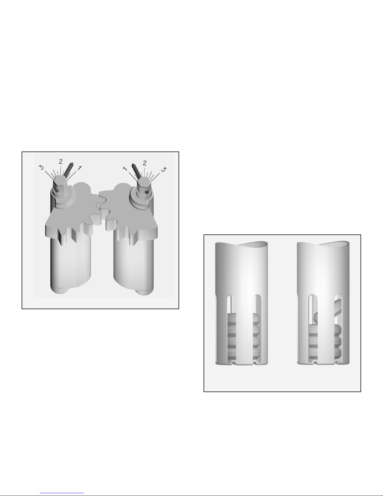
STATIONARY INSERT
The Series 4000 has a stationary insert that holds the internal
components of the tablet feeder in place. The stationary
insert has tapered locating holes to properly position and
support the chemical feed tubes when installed. On all
models, the insert is open on the inlet end to facilitate the
adjustment of the inlet bae. For models incorporating the
standard weir plates, the stationary insert does not extend
all the way to the outlet end wall of the tablet feeder. This
section is left open to allow for the removal and replacement
of weir plates. In models incorporating the optional outlet
sluice, the insert extends completely to the outlet end
wall. The sluice sections are held in proper position by the
stationary insert. A molded hex nut on the top of each sluice
section protrudes through the insert to hold the sluice in place
and allow for adjustment. Indicator pins attached to the hex
nuts show the sluice opening in inches on a scale engraved
into the top of the stationary insert. The stationary insert is
securely riveted to the body of the Bio-Dynamic Series 4000
tablet feeder at the factory.
FIXED WEIR
The tablet feeder is supplied with interchangeable 1", 2" and
3" outlet weir plates. Decreasing the width of the weir will
raise the liquid level in the feeder and increase the chemical
dosage. The outlet weir plates slide into vertical support ribs
4
TIERED FLOW DECK
The multi-tiered ow deck of the Series 4000 tablet feeder
allows consistent chemical application to low, sustained,
variable, intermittent and surge ows. Liquid is channeled
through the three tiers of the ow deck according to the
hydraulic load. In low ows, liquid is directed toward the
feed tubes to accomplish the desired chemical dosage. In
higher ows, liquid is directed across the entire width of the
feeder to maintain the chemical dosage level. The lowest
tier of the ow deck is the inert drainage tier. The inert
drainage tier directs liquid to the feed tubes during low ow
conditions and forms a drainage channel to dry the tablets
when there is no ow. As the ow increases up to 3 gallons
per minute, the liquid is channeled through the intermediate
ow tier, contacting more tablets. The shape of this tier
causes the ow to accelerate as it passes the feed tubes.
At ow rates over 3 gallons per minute, the liquid rises to
the upper ow tier which dissipates the ow velocity and
produces a consistent chemical dosage. The ow deck
automatically channels these variable ows through the
appropriate tier as shown in the sketch on page 7.
BAFFLE ADJUSTMENT TOOL
INTERCHANGEABLE WEIR PLATES
molded into the tablet feeder body and engage into a channel
in the ow deck. There is no need for external fasteners
or adhesive to install the weir plates. The stationary
insert is open at the outlet end of the ow deck to facilitate
interchangeability of the weir plates. When installing a weir
plate, make sure the plate is completely engaged in the
support ribs and rmly against the ow deck. To change a
weir plate, lift vertically to remove the weir and push down
evenly to install the new plate.
ADJUSTABLE OUTLET SLUICE
The optional outlet sluice can be completely adjusted from
a 1" to 3" width and provides precise control over chemical
dosage. Chemical application can be customized to meet
specic treatment requirements by using the outlet sluice.
Decreasing the width of the sluice will raise the liquid level in
the unit and increase the chemical dosage. The stationary
insert extends completely to the feeder outlet to hold the
sluice in position. The right and left sections of the sluice
are synchronized by molded gears that assure accurate
adjustment. Adjust the sluice by rotating one of the molded
hex nuts that are located at the top of each sluice segment.
The hex nuts protrude through the stationary insert and
can be rotated with a standard 1" socket. Indicator pins on
the hex nuts show the sluice opening in inches on a scale
5
engraved into the top of the stationary insert. Each tablet
feeder utilizing one or more riser sections for direct burial
will include an adjustable outlet sluice. Follow these steps
to adjust the outlet sluice:
1. Remove the feeder lid.
2. Place a 1" socket with the appropriate extension handle
over one of the hex nuts that protrude through the
stationary insert.
3. Rotate the hex nut toward the outside of the feeder to
increase sluice width or toward the inside of the feeder
to decrease sluice width. The indicator pins show the
opening in inches on the engraved scale.
4. If you have rotated the hex nut too far, simply move
the socket to the other hex nut and rotate the sluice
back to the desired position.
5. Wait at least one hour and sample the euent. If
additional adjustment is necessary, repeat steps 1-4.
6. If the desired adjustment is not accomplished, see the
Chemical Application section of this manual.
7. Note setting on service record and replace lid.
FILLING AND INSTALLING FEED TUBES
Before handling any chemical tablets, carefully read the
product container label and the CAUTION section of these
instructions. When lling feed tubes, always wear rubber
gloves and safety goggles or a face shield for proper
protection. Follow all handling instructions for the chemical
tablets used. To ll the feed tube:
1. Remove feed tube from the tablet feeder.
2. Rinse feed tube and cap thoroughly with fresh water. Dry
as required.
3. Hold tube, slotted end up, at a 30° to 45° angle and slide
tablets into the open feed tube, one tablet at a time.
4. Insure that each tablet lies at, against the next and evenly
on top of one another, in the feed tube.
5. Use a gloved hand to retain the tablets inside the open
end of the inverted tube until it has been completely lled.
6. Carefully return the tube to the upright position.
7. Replace cap and slide feed tube through the stationary
insert and into the retaining rings in the ow deck.
8. Align the two vertical parting lines, one on each side of
the tube, with the direction of ow through the feeder.
9. Insure the notches in the top of the feed tube are per-
pendicular to the ow direction. The window portions at
the bottom of the feed tube will now be facing upstream
and downstream respectively.
The precise control provided by the Series 4000 tablet
feeder allows adjustment of the chemical application with
all feed tubes lled and installed. Feed tubes should be
relled at the approximate intervals suggested in the Series
4000 Component Conguration chart on page 3 of this
manual. Each installation will have an individual chemical
consumption pattern which should be monitored during the
initial weeks of operation to establish a rm rell schedule.
Utilize the Chemical Consumption Record on the back of
this manual to track your rell pattern.
FILLING FEED TUBES
CORRECT INCORRECT
OUTLET SLUICE WITH SCALE

REMOTE REMOVAL SYSTEM
A remote feed tube removal system is available for direct
burial installations to allow for safe removal, recharge and
reinstallation of the chemical feed tubes from grade. The
remote removal system consists of four top-threaded feed
tube caps, four corrosion resistant extensions and four
corrosion resistant handles. For use, replace the standard
cap with the top-threaded cap. The top-threaded cap
locks into the feed tube, then the extension and handle
are threaded onto the top of the new cap. The feed tube is
then returned to its proper position within the tablet feeder.
6
Additional extensions are available for deeper installations
and can be added or removed any time. The extensions
and handles remain in place during system operation
and standard feed tube lling instructions apply. A bae
adjustment tool is available that threads into the extension
handle in the same manner as the top-threaded caps. To
adjust the bae, remove one feed tube and extension
handle. Remove the handle from the feed tube and thread
the handle onto the bae tool. Place the hook portion of
the tool through the hole in the inlet bae. Adjust the bae
up or down as shown in the sketch on page 4.
FEED TUBE CLEANING BRUSH
A brush for cleaning the feed tubes and ow deck is available
from your local Bio-Dynamic distributor. To use the brush,
remove the extension handle from the top-threaded feed
tube cap and screw the brush into the handle. Wet the
brush with fresh water, hold the feed tubes over the tablet
feeder and gently swab the inside of each feed tube. Lower
the brush into the tablet feeder and through the openings
in the stationary insert. Clean the ow deck and inside of
the feeder. Thoroughly rinse and remove the brush, attach
the top-threaded feed tube cap to the handle and reinstall
the feed tube into the tablet feeder.
EXTENSION HANDLES WITH CAP
BIO-SANITIZER®DISINFECTING TABLETS
If the tablet feeder is to be used for the disinfection of water
or wastewater, a (10 lb., 25 lb., 45 lb. or 100 lb.) supply of
Bio-Sanitizer tablets is available from your local distributor.
Bio-Sanitizer tablets insure dependable disinfection for
water and wastewater treatment system ow and other
applications where a predictable long-term source of
chlorine is desirable. The tablets are manufactured
from pure calcium hypochlorite and contain at least 70%
available chlorine. Registered with the USEPA for water
and wastewater treatment, the tablets incorporate beveled
edges to enhance the chemical dissolution pattern, providing
eective and economical bacteria killing power. Each tablet
is 25/8" diameter, compressed to a 13/16" thickness, has an
approximate weight of 5 ounces and is white in color for easy
identication. The chemical application rate of the tablets
remains consistent at peak ow factors as high as four.
CAUTION: The improper handling of Bio-Sanitizer
tablets may cause personal injury or property damage.
Keep out of the reach of children and do not allow the
tablets or feed tubes to contact skin, eyes or clothing.
Tablets may be fatal if swallowed and tablet dust is
irritating to the eyes, nose and throat. Do not handle the
tablets or feed tubes without rst carefully reading the
product container label and/or the handling and storage
instructions. Do not add tablets to any dispensing
device or storage container containing remnants of any
other product, especially petroleum based products or
swimming pool chlorine. Do not use swimming pool
chemicals in Bio-Dynamic tablet feeders. For additional
information about Bio-Sanitizer tablets contact your
local distributor.
BIO-NEUTRALIZER®DECHLORINATION TABLETS
If the tablet feeder is to be used for the dechlorination
of water or wastewater, a (25 lb. or 45 lb.) supply of
Bio-Neutralizer tablets is available from your local distributor.
Containing 35% sodium sulte, the tablets are manufactured
to neutralize both free and combined chlorine. Bio-Neutralizer
tablets incorporate beveled edges to enhance the chemical
dissolution pattern. Each tablet is 25/8" diameter, compressed
to a 13/16" thickness, weighs approximately 5 ounces and is
green in color for easy identication. The tablets dissolve
slowly, releasing controlled amounts of chemical for the
instantaneous removal of residual chlorine from the water
or wastewater ow. The chemical application rate of the
tablets remains consistent at peak ow factors as high
as four. Bio-Neutralizer tablets are formulated to remove
chlorine residuals to non-detectable levels.
CAUTION: Bio-Neutralizer tablets or feed tubes should
not be mixed with Bio-Sanitizer tablets or the remnants
of any other product. Do not handle tablets or feed tubes
without rst carefully reading the product container
label, SDS information and the safety, handling and
storage instructions. For additional information about
Bio-Neutralizer tablets contact your local distributor.

PLACING THE BIO-DYNAMIC®ON-LINE
After adjusting the inlet bae, lling and installing the
feed tubes and selecting the outlet weir or adjusting
the outlet sluice, the tablet feeder is ready to be placed
on-line. Be sure the entire liquid stream from the facility
being served ows through the tablet feeder. Conrm
that the proper chemical tablets are being used. After the
system has been in operation for at least one hour, draw
a sample of the treated euent from the feeder outlet or
the contact chamber inlet to test the chemical application.
For chlorination applications, testing can be done using a
chlorine test kit, available from your Bio-Dynamic distributor,
or a DPD Colorimetric test as outlined in the most recent
edition of Standard Methods for the Examination of Water
and Wastewater. Multiple samples must be taken to insure
that the system has reached equilibrium. Take samples at
15 minute intervals. When three or more samples produce
the same results, the system has reached equilibrium.
OPERATIONAL ADJUSTMENT
If the chemical dosage requires alteration, the Series
4000 tablet feeder can be adjusted during operation. You
do not need to take the system o-line or to disassemble
any component of the unit. Chemical application can be
increased by decreasing the width of the weir or sluice and
also by raising the inlet bae. Conversely, chemical dosage
can be decreased by increasing the width of the weir or sluice
and by lowering the inlet bae. The precise control provided
by the Series 4000 tablet feeder allows adjustment of the
chemical dosage to almost any requirement while all feed
tubes are charged with tablets. Adjustment of the chemical
dosage and potential operational problems are covered
in this manual. If there are additional questions regarding
operation, contact your local Bio-Dynamic distributor. For
further reference, a red identication tag with the contact
information of the manufacturer is attached to the feeder.
7
ROUTINE MAINTENANCE
The tablet feeder requires very little maintenance other
than periodic cleaning and relling of the feed tubes. When
performing any maintenance, always wear rubber gloves and
safety goggles or a face shield and follow the procedures
outlined in the handling instructions for the chemicals used
in the feeder. Before relling the feed tubes, rinse each
tube and cap thoroughly with fresh water. Occasionally,
a feed tube may need to be cleaned with a brush. When
relling feed tubes, check the inside of the feeder and rinse
any residue with a low pressure hose. The liquid ow will
normally prevent accumulation of debris during routine
operation. Debris that may become lodged within the feeder
can be removed with the cleaning brush or a gloved hand.
INSUFFICIENT CHEMICAL APPLICATION
Check to see that the tablets are not jammed in the feed tube.
If the tablets are jammed, remove and properly rell the feed
tubes. Make sure the feed tubes are resting at in the ow
deck retaining rings. If the feed tubes are properly lled and
resting securely on the ow deck, check the system for a
hydraulic overload. Surges over and above the anticipated
system ow rate can cause temporary reductions in chemical
application. If adjustment of the Bio-Dynamic tablet feeder
is necessary, reduce the width of the outlet weir or sluice.
The inlet bae may also be raised to increase chemical
dosage. These adjustments can be made during system
operation. Test the chemical application after adjustment
to conrm the system is performing as desired.
OVER APPLICATION OF CHEMICAL
Too much chemical can be applied if the outlet is restricted.
Check the feeder for blockage. If the outlet is not obstructed,
increase the width of the outlet weir or sluice. The inlet
bae can also be lowered to reduce chemical application.
These adjustments can be made during system operation.
If the outlet weir or sluice is at its maximum width and the
inlet bae is at its lowest setting, chemical application can
be reduced even further by leaving one or more feed tubes
empty. Empty tubes must still be installed within the tablet
feeder to maintain the hydraulic ow pattern. The lowest
application of chemical is accomplished by placing the lled
feed tubes closest to the system outlet. If this application
is too low, the lled feed tubes can be placed closest to the
system inlet. Test the chemical application after adjustment
to conrm the system is performing as desired.
INTERMITTENT USAGE
If a period of intermittent use or extended period of
non-use is anticipated, the feed tubes should be removed
and stored in a well-ventilated, dry, secure location. Refer to
the tablet container label for detailed safety, storage and/or
disposal instructions for the chemical tablets. Reinstall the
feeder lid securely for the period of time that the system
will be unattended. If a cable locking device has been
installed, it should be locked during the period of non-use.
TIERED FLOW DECK
A) DRAINAGE TIER B) INTERMEDIATE TIER C) UPPER TIER

SYSTEM SAFETY
All installations not protected by a safety fence or locked
grating should be equipped with an optional cable locking
device as available from the manufacturer. The locking
device will assure that only authorized personnel have access
to system components. Conned space entry equipment
(Occupational Safety and Health Regulations OSHA
29,CFR1910.146) is not required for a properly installed
Series 4000 tablet feeder with optional riser. Maintenance
of the tablet feeder can be performed from grade. Under no
circumstances should operating personnel put their face,
head or torso into the tablet feeder or risers. Toxic fumes
present in wastewater and/or tablets may accumulate within
the feeder and cause personal injury or death. Thoroughly
read chemical container label before use. Safety/reinforcing
struts are provided for unit integrity as well as to restrict
means of entry into the tablet feeder. Feeders should not
be buried without these safety struts securely in place. If
struts are removed during the installation process, they
must be reinstalled at the very top of the nal installation.
BIO-DYNAMIC®LIMITED WARRANTY
SERIES 4000 CHEMICAL CONSUMPTION RECORD
For your reference, please document component setting, chemical consumption and maintenance on the following chart:
The Bio-Dynamic Series 4000 tablet feeder is backed
by a comprehensive ten year limited warranty. The
purchaser is protected from defects in material and
workmanship, under normal use and service, for a
period of ten years from the date of original purchase.
The Bio-Dynamic Series 4000 distributor will provide a
warranty registration card, as well as detailed warranty
and exchange information, to each purchaser. This
warranty is not eective unless the warranty registration
card is returned to the factory within 30 days of
purchase. If the tablet feeder or components require
service or replacement, do not use or dismantle the unit.
Contact your local, authorized Bio-Dynamic Series 4000
distributor to arrange for service or replacement of the
system or component. After inspection, the distributor
will return the tablet feeder or component, as required,
to the factory and replace the necessary items according
to the terms of the limited warranty.
DATE DESCRIPTION
220 REPUBLIC STREET
NORWALK, OHIO, U.S.A. 44857-1156
TELEPHONE (419) 668-4471
FAX (419) 663-5440
www.norweco.com
DISTRIBUTED LOCALLY BY:
Norweco®, Norweco.com®, Singulair®, Modulair®, Travalair®, Singulair Green®, Ribbit Rivet®, Hydro-Kinetic®, Hydro-Kinetic Bio-Film Reactor®,
Evenair®, Lift-Rail®, Microsonic®, Bio-Dynamic®, Bio-Sanitizer®, Bio-Neutralizer®, Bio-Kinetic®, Bio-Static®, Bio-Gem®, Bio-Max®, Bio-Perc®,
Blue Crystal®, Phos-4-Fade®, Enviro-C®, ClearCheck®, ChemCheck®, Tri-Max®, Hydra-Max®, Service Pro®, MCD®, TNT®, WASP®, Grease Buster®and
“BUSTER” logo®are registered trademarks of Norwalk Wastewater Equipment Company, Inc.
©MMXI NORWECO, INC.
Popular Laboratory Equipment manuals by other brands

Teledyne Cetac Technologies
Teledyne Cetac Technologies ASX-560 Alignment Guide

Ametek Land
Ametek Land Fti-E installation guide

Macherey-Nagel
Macherey-Nagel NucleoMag SEP user manual

Selecta
Selecta STERILBIO quick start guide

Adam Equipment
Adam Equipment ANTI-VIBRATION TABLE Assembly instruction

MCi
MCi C Series Operation manual

Hach
Hach PHOSPHAX sigma High Range user manual

ScanSpeed
ScanSpeed Mini Service manual

Nordson
Nordson CoolWave 2 instruction sheet

D&H
D&H Lifelabs AquaSolvo Eco AAE-5005 Series instruction manual

ThermoFisher Scientific
ThermoFisher Scientific Q Exactive GC quick start guide

biochrom
biochrom EZ Read 400 quick start guide


