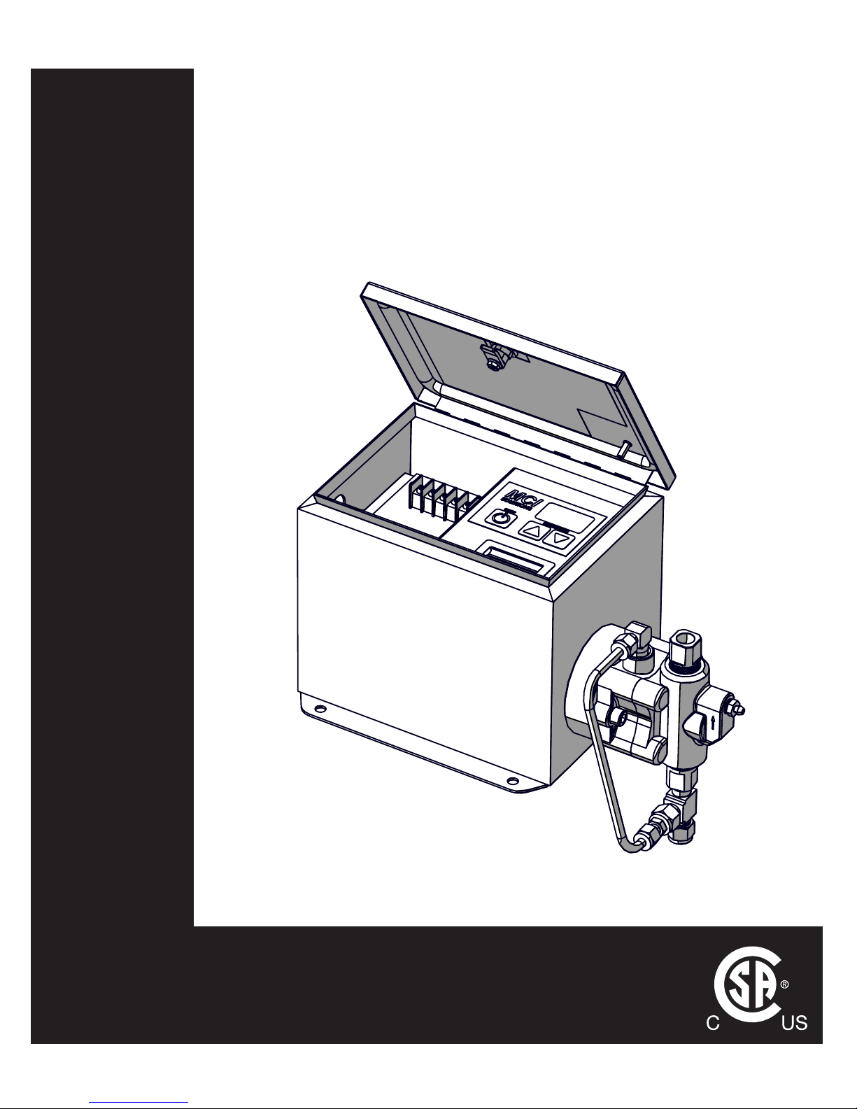
MCi C Series User manual

www.mcisolutions.ca
OPERATIONS MANUAL
MODEL C1 ELECTRIC CHEMICAL
INJECTION SYSTEM
C SERIES

GENERAL SAFETY
ii
www.mcisolutions.ca
Table Of Contents
General Safety 1
Symbol Usage . . . . . . . . . . . . . . . . . . . . . . . . . . . . . . . . . . . . . . . . . . . . . . . . 1
Proper Use . . . . . . . . . . . . . . . . . . . . . . . . . . . . . . . . . . . . . . . . . . . . . . . . . .2
Sources of Danger . . . . . . . . . . . . . . . . . . . . . . . . . . . . . . . . . . . . . . . . . . . . .2
Authorized Operators . . . . . . . . . . . . . . . . . . . . . . . . . . . . . . . . . . . . . . . . . . . 3
Personal Protective Equipment . . . . . . . . . . . . . . . . . . . . . . . . . . . . . . . . . . . . . 4
In Case of Emergency . . . . . . . . . . . . . . . . . . . . . . . . . . . . . . . . . . . . . . . . . . .4
System Specications 5
Electric Drive Dimensions. . . . . . . . . . . . . . . . . . . . . . . . . . . . . . . . . . . . . . . . . 5
Mounting Dimensions. . . . . . . . . . . . . . . . . . . . . . . . . . . . . . . . . . . . . . . . . . . 5
Static Head Requirements . . . . . . . . . . . . . . . . . . . . . . . . . . . . . . . . . . . . . . . . 6
Electrical Specications . . . . . . . . . . . . . . . . . . . . . . . . . . . . . . . . . . . . . . . . . . 6
General Specications . . . . . . . . . . . . . . . . . . . . . . . . . . . . . . . . . . . . . . . . . . . 7
Output Performance . . . . . . . . . . . . . . . . . . . . . . . . . . . . . . . . . . . . . . . . . . . . 7
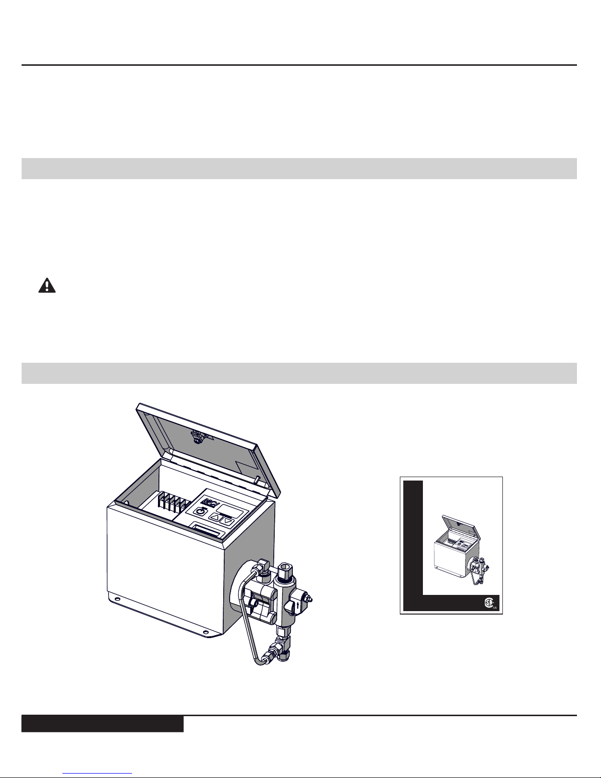
Installation 8
General . . . . . . . . . . . . . . . . . . . . . . . . . . . . . . . . . . . . . . . . . . . . . . . . . . . .8
Standard Package Contents . . . . . . . . . . . . . . . . . . . . . . . . . . . . . . . . . . . . . . .8
Plumbing Overview . . . . . . . . . . . . . . . . . . . . . . . . . . . . . . . . . . . . . . . . . . . .9
Power Supply . . . . . . . . . . . . . . . . . . . . . . . . . . . . . . . . . . . . . . . . . . . . . . . .12
System Startup . . . . . . . . . . . . . . . . . . . . . . . . . . . . . . . . . . . . . . . . . . . . . . .14
Operating Instructions 15
Controller Overview . . . . . . . . . . . . . . . . . . . . . . . . . . . . . . . . . . . . . . . . . . . . 15
Setting Flow Rate . . . . . . . . . . . . . . . . . . . . . . . . . . . . . . . . . . . . . . . . . . . . . . 16
Troubleshooting 18
Bill of Materials 21
Material Codes. . . . . . . . . . . . . . . . . . . . . . . . . . . . . . . . . . . . . . . . . . . . . . . . 21
General System Detail View . . . . . . . . . . . . . . . . . . . . . . . . . . . . . . . . . . . . . . .22
FMT Fluid End . . . . . . . . . . . . . . . . . . . . . . . . . . . . . . . . . . . . . . . . . . . . . . . . 23
Plunger Seals. . . . . . . . . . . . . . . . . . . . . . . . . . . . . . . . . . . . . . . . . . . . . . . . . 24
In-line Filter . . . . . . . . . . . . . . . . . . . . . . . . . . . . . . . . . . . . . . . . . . . . . . . . .25
Pressure Relief Valve . . . . . . . . . . . . . . . . . . . . . . . . . . . . . . . . . . . . . . . . . . . . 25
Maintenance 27
Preventative Maintenance Schedule . . . . . . . . . . . . . . . . . . . . . . . . . . . . . . . . . . 27
Lubrication Details . . . . . . . . . . . . . . . . . . . . . . . . . . . . . . . . . . . . . . . . . . . . . 28
Plunger Seal Maintenance Procedure . . . . . . . . . . . . . . . . . . . . . . . . . . . . . . . . . 28
Check Valve Maintenance. . . . . . . . . . . . . . . . . . . . . . . . . . . . . . . . . . . . . . . . . 35
Limited Warranty 38
Maintenance Log 39

1
www.mcisolutions.ca
The C1 Electric Chemical Injection System has been subjected to a safety test and quality acceptance in-
spection. Please ensure all safety instructions in this manual are clearly understood. Misuse or incorrect
operation of the System may cause serious injury or death
Only properly and trained personnel should be involved in the setting up, putting into service, in-
specting, servicing and repairing of this equipment.
Read and understand all instructions. Failure to follow the Dangers,
Cautions and Warnings contained in this owners manual may result in electric
shock, re, serious bodily injury or death
CAUTION!
General Safety
Symbol Usage
Designates an imminent danger. In case of non-observance of this infor-
mation, death or severe injuries are an imminent risk
Designates possibility of a dangerous situation. In case of non-observ-
ance of this information, death or severe injuries can occur
Designates areas where the potential for severe crush injury exists.
These crush injuries can result in serious bodily injury
Electrical Shock Hazard Warning indicates a potential injury hazard that
can result in serious bodily injury or death
Designates important user tips and other useful information
Designates important installation information that if not followed could
cause System failure
DANGER!
CAUTION!

GENERAL SAFETY
2
www.mcisolutions.ca
NOTICE TO INSTALLER: This manual must be left with the owner/operator of the System and kept
for future reference
Proper Use
This System uses a reciprocating positive displacement pump. It serves the purpose of conveying and
circulating liquids. The System and these operating instructions are intended for commercial use exclu-
sively
Severe skin injury can result from dangerous media used with this System.
(i.e. Aggressive, toxic and caustic media)
Unsuitable media can damage the pump and then escape into the surround-
ing area
If you intend to use dangerous media, the materials used for the pump parts
must be designed and compatible for this use
ANY form of liability on the part of the manufacturer shall be null and
void if the System has been modied by others without authorization
from MCI
When replacing parts in the System, use only spare parts approved by MCI. (Refer to the Bill of Materials
section in this manual for more information )
Always Disconnect power to the System before performing ANY maintenance
or repair activities
Sources of Danger
The System has been manufactured in compliance with CSA standards and complies with all applicable
safety requirements
Although most safety risks have been reduced through design and construction measures, residual risks
(i.e. explosive atmospheres, electrical, mechanical or thermal) cannot be excluded entirely during either
transport, maintenance and repair work, or regular operation
CAUTION!
CAUTION!
DANGER!

3
www.mcisolutions.ca
Authorized Operators
Only persons who have been properly authorized and trained by MCI or its authorized agent may work
on or with this equipment
The owner must:
■Clearly dene and ensure the observance of the responsibilities for all tasks performed in con-
nection with the System
■Make this manual accessible to all operations sta
■Make sure operations have read and understood all operating instruction
For Extra copies of this manual or for more information please visit us online
at: www.mcisolutions.ca
Or, Scan the following QR code with your smart phone for a direct link to
digital copies of all MCI Operation Manauls:
Maintenance, upkeep and electrical tasks should only be performed by
technically competent, trained and/or qualied personnel
Technically competent people, trained and qualied personnel are dened as individuals who:
■Possess sucient knowledge in a specic eld based on their specialized training and experi-
ence; and
■Are familiar with all applicable work safety and accident prevention regulations (i.e. lock-out or
tag-out safety procedures)
CAUTION!

GENERAL SAFETY
4
www.mcisolutions.ca
Personal Protective Equipment
Wear appropriate protective equipment especially when performing any
maintenance, inspection or cleaning task on the System
Oils, Lubricants and cleaning agents can cause skin reactions and irritation.
Avoid skin contact with all chemical used in connection with the System
In Case of Emergency
In case of Emergency originating from the System or from conditions in the surrounding area, the Sys-
tem must be switched o immediately
The System cannot be put back into operation until the emergency has been identied and corrected.
Ensure corrective actions are taken to prevent future occurrence
In case of res, use only suitable re-extinguishing agents
If the instructions in this manual are not adhered to or are inadequately
adhered to , the warranty shall become null and void and the CSA declar-
ation of conformity shall immediately cease to be valid
MCI makes no other warranty, including without limitation, any warranties or merchantability or of tness
for a particular purpose, whether express or implied. MCI will not be liable under any circumstances
whatsoever to the purchaser for any damages relating to loss of production, loss of product, environment
damage, or any incidental, consequential, special or punitive damages regardless of whether arising in
contract, strict liability, other tort or otherwise. The exclusive remedy of the purchaser for any and all
losses, injuries or damages resulting from the sale, use or handling of any product whether in contract,
warranty tort, negligence, strict liability or otherwise, will not exceed the purchase price paid, or at MCI’s
sole election, the repair or replacement of the product
CAUTION!
CAUTION!

5
www.mcisolutions.ca
System Specications
Electric Drive Dimensions
335 mm
(13.2 in)
370 mm
(14.5 in)
190 mm
(7.5 in)
330 mm
(13.0 in)
234 mm
(9.2 in)
LID CLOSED
Mounting Dimensions
173 mm
(6.8 in)
C/L TO C/L
163 mm
(6.4 in)
C/L TO C/L
7.9 mm
(0.313 in)
Diam. (x4)

GENERAL SAFETY
6
www.mcisolutions.ca
Static Head Requirements
MINIMUM (CL TO CL)
305 mm
(12.0 in)
Electrical Specications
Electrical Rating 24V DC
Classication CSA CLASS 1 DIVISION 2
Enclosure Rating Nema 3R
Temperature Code T4A
Motor Type 4 Pole Stepper Motor, 1.8 Degree Step
Inrush Current 950 (mA)
Avg. Power Consumption 450 (mA) MAX
Reverse Polarity Protection Standard
Analog Input [4-20 mA] Optional Upgrade [Innite Scale adjustments and
remote On/O capability]
Integrated Low Voltage Disconnect Standard [custoM set points AvAilAble]

7
www.mcisolutions.ca
General Specications
N-seal Leak Containment Adaptor Standard
Variable Speed Controller Electronic/ MOSFET
Electro-mechanical contactors / Relays N/A
Electro-mechanical Timers N/A
Dip Switch N/A
Fluid End Carbon Steel [316L S.S. Upgrade available]
Fluid End Suction and Discharge Seals OMX Fluoroelastomer®
Secondary Containment Static Seals Teon®
Seal Kit Dynamic Seals UHMW Polyethylene c/w Stainless Steel spring.
Plunger Material Tungsten Carbide
Operating Temperature -40 to +40 [oC]
Output Performance
1/4" Plunger 3/8" Plunger 1/2" Plunger 11/16" Plunger
Maximum Displacement Pressure [Psi] 3000 1500 750 400
Maximum Displacment Pressure [kPa] 20684 10342 5171 2758
Maximum Output Volume [Litres/day] 12 29 52 104
Minimum Output Volume [Litres/Day] 0.12 0.26 0.46 0.86

GENERAL SAFETY
8
www.mcisolutions.ca
Installation
General
Congratulations. You have chosen the nest, most accurate electrically powered chemical injection Sys-
tem available. Before Installation, please inspect the pump carefully for any possible in-transit dam-
age. If the pump appears damaged, call your local distributor or call MCI customer service direct at
+1.888.263.4565
Please ensure you have fully read and understood the general safety
section of this manual before proceeding with the System installation
The System is CSA approved for use in Class 1 Division 2 areas. It is the
responsibility of the owner to determine the classication of the area
where the System is to be installed
Standard Package Contents
C1 Electric Drive (x1)
Manual (x1)
OPERATIONS MANUAL
MODEL C1 ELECTRIC CHEMICAL
INJECTION SYSTEM
C SERIES
www.mcisolutions.ca
CAUTION!

9
www.mcisolutions.ca
The System is to be mounted securely in a safe location that satises the classication requirements.
The Systems Fluid End (Pump) must be oriented in a vertical position for proper check valve operation
Allow a minimum distance of 12 in. from the center line of the pump head to the lowest point on the
chemical storage container bulkhead to ensure adequate [positive]static head pressure is available. The
System relies on a positive suction pressure to run correctly [grAphic eXplAnAtion shown on pAge 6]
The membrane switch panel is covered with a clear plastic lm, remove prior to operating the System
Plumbing Overview
Only properly qualied and trained personnel should be involved in the
setting up , putting into service, inspecting, servicing and repairing of the
plumbing for the uid end
Ensure all National, Provincial/State and local codes are followed when plumb-
ing equipment. Failure to follow these codes can result in serious bodily injury
or death
The following plumbing suggestions are examples of typical installations only and may not be the best
suited method for your custom installation
Ensure all process valves are closed prior to disconnecting or re-installing any chemical injection System
To avoid over-pressuring chemical discharge lines MCI requires placing a properly tested and calibrated
Pressure Relief valve (PRV) between the discharge port of the uid end and the process injection point.
The set point must not exceed the pumps maximum discharge pressure [MAXiMuM dischArge pressures cAn be
found in the 'systeM specificAtions' section under 'output perforMAnce']
Failure to add a CERTIFIED and CALIBRATED Pressure Relief Valve (PRV)
to the System is inherently unsafe. It can cause catastrophic System
damage and voids all System warranty. MCI is not responsible for any
damage caused by exceeding maximum System pressure. MCI oers
complete PRV solutions for all Systems. Please contact customer service
for latest pricing and availability: +1.888.263.4565
CAUTION!

GENERAL SAFETY
10
www.mcisolutions.ca
Standard Connection Points
Removing foreign debris from suction lines and chemical storage containers
will greatly extend the life of all dynamic seals used in the System. It is highly
recommended to use a pre-suction in-line lter on all Systems. MCI oers
in-line lter kits for all pump models. Please contact customer service for the
latest pricing and availability: +1.888.263.4565
Secondary Containment Line
1. Fluid End Discharge Point - 1/4” Fem. NPT
2. Pressure Transducer Port - 1/8" NPT
3. Fluid End Suction Point - 3/8”Tube
3
1
2
1. Secondary containment line - 1/4”Tube
1

11
www.mcisolutions.ca
Pressure Relief Valve Tie-In [TYPICAL ARRANGEMENT SHOWN]
Pressure relief valve kits are available direct from MCI. Kits include all tubing
[where applicable] and ttings required to complete the installation. Contact
customer service for more information: +1.888.263.4565
Suggested in-Line Filter [TYPICAL ARRANGEMENT SHOWN]
1. Pressure Relief Valve
2. Male Connector - 1/4” NPT x 3/8”Tube
3. Run Tee - 1/4” NPT [Main Discharge Point]
4. Stainless Steel Tubing [.035] - 3/8”
5. Tube Connector - 3/8”
6. Union Tee - 3/8”
6
5
4
3
1
2
1. In-line lter - 440 Micron
2. Tube connector - 3/8”
12

GENERAL SAFETY
12
www.mcisolutions.ca
In-line lter assemblies are available direct from MCI. Kits include all tubing
[where applicable] and ttings required to complete the installation. Contact
customer service for more information: +1.888.263.4565
The 1/4”NPT drain port shown [Arrow] is a general
System drain port [DO NOT PLUG OFF] This port
must remain open or plumbed to a designated
containment area
Without routine maintenance it is possible for seal
bypass from the low pressure side to exit this port.
Ensure proper containment areas are in place and
suggested routine seal maintenance procedures
are followed to prevent spills
Power Supply
When wiring the System follow cable orientation labels found on the inside of
the enclosure lid. Failure to orientate wiring properly may result in damage to
the on-board electronics and could cause serious bodily injury or death
To protect the System and associated components the pump box must be
connected to ground. All electrical connections must satisfy National, Provin-
cial/State and local electrical codes
SYSTEM CAN START AUTOMATICALLY - Before connecting power to the
control board ensure that you and all tools used in setup are clear of moving
parts, serious bodily injuries can occur
When connecting cables to the control module ensure keyed connections
are tight. Loose connections can cause arcing and erosion which destroy the
integrity of the connections

13
www.mcisolutions.ca
Power Supply Requirement - 24 V DC
Power supply cannot exceed 28 V or damage to electrical components will
result
Power Supply Wiring
Do not connect or disconnect motor while the controller is powered or
damage to the controller can result
To ensure safe and proper System operation DO NOT exceed maximum
recommended injection pressures. Maximum System pressures are avail-
able under the 'systeM specificAtions' section of this manual
1. Wiring Terminal Block - #6-32 Screws
2. Knockout [To Accept 1/2" Liquidtight Conduit]
3. Programming Port
4. In-line fuse Holder*
* Accepts 0.25 x 1.25” fast acting 2.5A glass fuse
2
4
3
1
CAUTION!
CAUTION!

GENERAL SAFETY
14
www.mcisolutions.ca
System Startup
STEP 1
WIRING INTERFACE
Wire 24V DC power supply out to the main terminal block on the pumps front access panel, always
ensure wiring polarity is correct to prevent system damage. CAUTION: System will start automatically
Model C1 pumps are equipped with COLDStart technology. This technology ensures proper operation
during the winter months by temporarily increasing the motors supply current at startup. When the sys-
tem is in COLD start mode 'UP' will appear on the digital display . The System will automatically revert to
normal operating conditions when its warm up routine is complete [~10 Minutes]
If the ambient temperature is warmer than -10O C the COLDStart routine is not required. To bypass the
routine early, press the 'UP' or 'DOWN' arrow button once to resume normal operation
STEP 2
If desired 'Strokes Per Minute' [SPM] setting is known adjust desired pump rate by pressing the UP/
DOWN stroke rate keys on the control module until desired SPM rate is displayed
If desired stroke rate is not known please refer to the next section in this manual 'Operating Instructions'
for a complete set of instructions

15
www.mcisolutions.ca
Operating Instructions
Controller Overview
Ensure you have fully read and understood all sections of this manual before
operating this equipment
MCI’s user interface has been designed to simplify the process of setting and adjusting the chemical
injection drive. This section has been included to explain how to use the 3 button controller interface
CAUTION!
ON / OFF Switch-
Cycles power to
pump
Integrated RED LED - (Blinks
when power is supplied to the
board and the pump is in the
OFF position)
Digital Stroke Rate Display -
Press the UP/DOWN arrow to
activate display when the pump
is cycling [strokes per Minute]
UP / DOWN Arrows - Used to
adjust the pumps strokes per
minute rate setting

GENERAL SAFETY
16
www.mcisolutions.ca
Setting Flow Rate
STEP 1
Determine Systems plunger size *[1/4”, 3/8”, 1/2” or 11/16” Diameter]
*plunger id lAbels Are included with Mci systeMs to help quickly identify plunger size. the decAl cAn be found on
the front top right hAnd corner of your electric drive enclosure
STEP 2
When safe to do so open the enclosure access panel and locate the pump rate chart found inside the
pump enclosure lid [shown below]
Pump Rate
Chart
PUMP RATE CHART
PLUNGER SIZE (DIAMETER)
STROKES
PER
MINUTE
1/4" 3/8" 1/2" 11/16"
LITRES PER DAY (OUTPUT)
0.1 0.12 0.26 0.46 0.86
0.2 0.23 0.44 0.79 1.49
0.3 0.35 0.66 1.20 2.26
0.4 0.46 0.85 1.60 3.02
0.5 0.58 1.10 2.00 3.78
1.0 1.0 2.2 3.9 7.37
1.5 1.4 3.3 6.0 11.3
2.0 2.0 4.4 7.9 14.9
2.5 2.5 5.5 9.9 18.7
3.0 2.0 6.6 11.8 22.3
3.5 3.4 7.7 13.8 26.0
4.0 3.9 8.8 15.7 29.7
4.5 4.4 9.9 17.7 33.4
5 4.9 11.1 19.7 37.2
5.5 5.4 12.2 21.7 41.0
6.0 6.0 13.3 23.6 44.6
6.5 6.4 14.4 25.6 48.4
7.0 6.9 15.5 27.5 52
7.5 7.4 16.7 29.6 55.9
8.0 7.9 17.7 31.5 59.5
8.5 8.3 18.9 33.5 63.3
9.0 8.8 19.9 35.4 66.9
9.5 9.4 21.1 37.4 70.7
10.0 9.7 22.2 39.4 74.5
11.0 10.8 24.4 43.4 82.0
12.0 11.8 26.6 47.3 89.4
13.0 12.8 28.8 51.3 96.9
14.0 13.8 31.0 55.2 104.3
15.0 14.8 33.2 59.1 111. 7
(CONTINUED)
DO NOT EXCEED THE
SYSTEMS MAXIMUM
DISCHARGE PRESSURE
AS SHOWN BELOW
PLUNGER
SIZE
(DIAMETER)
MAXIMUM
PRESSURE
(PSIG)
1/4" 3000
3/8" 1500
1/2" 750
11/16" 400
STEP 3
Review pump rate chart and ensure the intended discharge pressure is within the maximum discharge
pressure rating of the System. do not exceed maximum operating pressure or system damage can occur
PUMP RATE CHART
PLUNGER SIZE (DIAMETER)
STROKES
PER
MINUTE
1/4" 3/8" 1/2" 11/16"
LITRES PER DAY (OUTPUT)
0.1 0.12 0.26 0.46 0.86
0.2 0.23 0.44 0.79 1.49
0.3 0.35 0.66 1.20 2.26
0.4 0.46 0.85 1.60 3.02
0.5 0.58 1.10 2.00 3.78
1.0 1.0 2.2 3.9 7.37
1.5 1.4 3.3 6.0 11.3
2.0 2.0 4.4 7.9 14.9
2.5 2.5 5.5 9.9 18.7
3.0 2.0 6.6 11.8 22.3
3.5 3.4 7.7 13.8 26.0
4.0 3.9 8.8 15.7 29.7
4.5 4.4 9.9 17.7 33.4
5 4.9 11.1 19.7 37.2
5.5 5.4 12.2 21.7 41.0
6.0 6.0 13.3 23.6 44.6
6.5 6.4 14.4 25.6 48.4
7.0 6.9 15.5 27.5 52
7.5 7.4 16.7 29.6 55.9
8.0 7.9 17.7 31.5 59.5
8.5 8.3 18.9 33.5 63.3
9.0 8.8 19.9 35.4 66.9
9.5 9.4 21.1 37.4 70.7
10.0 9.7 22.2 39.4 74.5
11.0 10.8 24.4 43.4 82.0
12.0 11.8 26.6 47.3 89.4
13.0 12.8 28.8 51.3 96.9
14.0 13.8 31.0 55.2 104.3
15.0 14.8 33.2 59.1 111.7
(CONTINUED)
DO NOT EXCEED THE
SYSTEMS MAXIMUM
DISCHARGE PRESSURE
AS SHOWN BELOW
PLUNGER
SIZE
(DIAMETER)
MAXIMUM
PRESSURE
(PSIG)
1/4" 3000
3/8" 1500
1/2" 750
11/16" 400
Example: 1/4” Plunger has a Maximum discharge pressure of 3000 psig

17
www.mcisolutions.ca
STEP 4
Select desired output volume from appropriate 'Litres Per Day' column for your specied plunger size.
Determine the 'Strokes Per Minute' setting for your chosen output volume by looking to the far left of
the selected volume row. [see example below]
Example: To achieve 2.0 Litre Per Day output volume with
a 1/2" Plunger the strokes per minute setting is 0.5
(1/4”) (3/8”) (1/2”)
PUMP RATE CHART
PLUNGER SIZE (DIAMETER)
STROKES
PER
MINUTE
1/4" 3/8" 1/2" 11/16"
LITRES PER DAY (OUTPUT)
0.1 0.12 0.26 0.46 0.86
0.2 0.23 0.44 0.79 1.49
0.3 0.35 0.66 1.20 2.26
0.4 0.46 0.85 1.60 3.02
0.5 0.58 1.10 2.00 3.78
1.0 1.0 2.2 3.9 7.37
1.5 1.4 3.3 6.0 11.3
2.0 2.0 4.4 7.9 14.9
2.5 2.5 5.5 9.9 18.7
3.0 2.0 6.6 11.8 22.3
3.5 3.4 7.7 13.8 26.0
4.0 3.9 8.8 15.7 29.7
4.5 4.4 9.9 17.7 33.4
5 4.9 11.1 19.7 37.2
5.5 5.4 12.2 21.7 41.0
6.0 6.0 13.3 23.6 44.6
6.5 6.4 14.4 25.6 48.4
7.0 6.9 15.5 27.5 52
7.5 7.4 16.7 29.6 55.9
8.0 7.9 17.7 31.5 59.5
8.5 8.3 18.9 33.5 63.3
9.0 8.8 19.9 35.4 66.9
9.5 9.4 21.1 37.4 70.7
10.0 9.7 22.2 39.4 74.5
11.0 10.8 24.4 43.4 82.0
12.0 11.8 26.6 47.3 89.4
13.0 12.8 28.8 51.3 96.9
14.0 13.8 31.0 55.2 104.3
15.0 14.8 33.2 59.1 111.7
(CONTINUED)
DO NOT EXCEED THE
SYSTEMS MAXIMUM
DISCHARGE PRESSURE
AS SHOWN BELOW
PLUNGER
SIZE
(DIAMETER)
MAXIMUM
PRESSURE
(PSIG)
1/4" 3000
3/8" 1500
1/2" 750
11/16" 400
LITRES PER DAY
STROKES
PER
MINUTE
(11/16”)
STEP 5
Finally, set your desired 'Strokes Per Minute' rate on the pump controller by pressing the UP/DOWN
stroke rate arrows until the desired setting is displayed
Due to System design variances such as instrumentation and media viscos-
ities it is important to always conrm injection rates using a calibrated tank
gauge. Adjust rate settings as required
....

GENERAL SAFETY
18
www.mcisolutions.ca
Troubleshooting
Symptom Potential Cause(s) Recommendation(s)
Electric drive does
not cycle when
powered
Pump controller is o Press the On/O button to cycle power
Loose or damaged power supply wiring Conrm all connections are securely fastened and that no mechanical
damage to wiring has occurred
Re-connect wiring and thread together tightly
Wiring polarity reversed on main power
supply cable
[see 'instAllAtion' section of this MAnuAl for
wiring diAgrAM]
Reverse wiring if found to be incorrect.
[Warning: Control module boards manufactured prior to 2010 may not
be equipped with reverse polarity protection and if powered in a reverse
condition will require replacement]
Damaged fuse Remove fuse holder cap and inspect fuse for damage. Replace if required
[0.25 x 1.25” - 2.5A]
Low voltage condition *
*if your systeM is equipped with the integrAted
low voltAge disconnect [lvd] the screen will
displAy 'pp' indicAting Apower probleM [low
voltAge condition]
Conrm 24V DC power supply is available to the control module with a
volt meter. Replace or repair power supply as required
If the System is running o a DC battery bank it is recommended to dis-
connect the charging source [i.e. solAr pAnels]before checking line voltage
to ensure accurate results
Damaged charge regulator Conrm charge regulator is outputting 24-28V. If your charge regulator
is equipped with a low voltage disconnect make sure to test its function-
ality and set points
Controller display
does not respond to
pressing on/o or
stroke rate buttons,
but the drive is
cycling normally
Pump is in analog mode [4-20 mA input] If your pump is equipped with the optional 4-20 mA analog input it will
override manual entries when in remote mode. Disconnecting the 4-20
mA input cable will resume normal manual operation
Pump is chattering
or not stroking the
full stroke [1 inch]
note: during norMAl
wArM up routine cycles
['up' shown on displAy]
the puMp will cycle
hAlf strokes And does
not indicAte AprobleM
with the drive
Low voltage condition Conrm 24V power supply is available to the control module with a volt
meter
If the System is running o a DC battery bank it is recommended to dis-
connect the charging source [i.e. solAr pAnels]before checking line voltage
to ensure accurate results
This condition can cause damage to the Systems drive if left for ex-
tended periods. If after identifying and correcting a voltage prob-
lem and the drive is still found to chatter it is recommended to send
the System in for inspection as motor bearings may be damaged
Discharge Isolation valve(s) closed If any valves are found to be closed and if safe to do so, open valves
Original controller replaced MCI oers many drive options that require specic controllers. Before
installing a new pump controller please contact MCI customer service:
+1.250.888.4565 to conrm compatibility. Please provide the Systems
model and serial number to conrm compatibility
Pumps maximum rated discharge pres-
sure has been exceeded
Please conrm your pumps maximum output pressure rating. This can
be found under the 'Specications' section of this manual. It is very im-
portant this pressure not be exceeded. It is unsafe and will cause pre-
mature System failure.
Damaged Control Module Contact customer service for repair options +1.250.888.4565
This manual suits for next models
1
Table of contents
Popular Laboratory Equipment manuals by other brands

Fischione
Fischione 1060 SEM Mill instruction manual

Endress+Hauser
Endress+Hauser Analytik Jena Biometra TOne Short manual

Veracity
Veracity Pointsource quick start guide

Okolab
Okolab H201-ENCLOSURE-DMi8-LASERSAFE-158 Assembly manual

Ecowell
Ecowell Homeguard manual

Esco Medical
Esco Medical Miri MRI-6A10/XQ-1 Installation procedures

Sutter Instrument
Sutter Instrument XenoWorks BRM Operation manual

Mestra
Mestra R-100210 manual

Amnis
Amnis ImageStream Mark-II Quick start guides

Distek
Distek 3100 Series Quick start instructions

Agilent Technologies
Agilent Technologies 6100 Series Familiarization guide

Leica
Leica CM1510S instruction manual