NOTTINGHAM ANALOGUE STUDIO Deco User manual

Nottingham
Analogue Studios
Dealer Manual

Table of Contents
1. Essential tools
2. Set up Specs
Distance from Tone arm center to spindle
Effective Mass of Tonearms
Nottingham Cartridge specs
3. Set up tips
The meaning of tight
Thoughts on VTA
Thoughts on Bias (anti-skate)
Motor height
Getting the tone arm position right
Installing and positioning the cartridge
Getting the right amount of oil in the bearing
Positioning your table – (including leveling, mains connection)
What about the plinth?
4. Maintenance & Service
Cleaning Belts
Changing Oil
Leveling the platter
5. Manuals
Horizon
Space Deck
Dais
Heavy Kit
Wave Mechanic
6. General Specs
Weights
Dimensions
7. Prices
8. Warranty information

Essential tools
Included
Allen Keys (metric)
Spirit Level
Protractor
Additional tools
Stylus Pressure Gauge - The Shure SFG gauge works well
Small Electric Screwdriver - With a clutch so you won’t over tighten
Cartridge Mounting Screws - Spares are helpful so when you drop them you don’t
have to go crazy looking for them
A Good pair of Needle Nosed Pliers Not Tweezers!
A Ruler w/ Metric scale - At least 12 inches long
A Good pair of Ears - Nothing will tell you more than listening to music

Set up Specs
Distance from Tone arm center to spindle
Interspace and RB-250 - 222 mm
Space Arm - 210 mm
Anna (10”) - 222 mm
Anna (12”) - 294 mm
Effective Mass of Tone arms*
RB-250 - 11.25 grams
Interspace - 11.25 grams
Space Arm - 12.5 grams
Anna (10”) - 13 grams
Anna (12”) - 15.5 grams
* All measurements are approximate
Nottingham “Tracer One” cartridge specs
Cartridge Type - Moving Magnet
Output - 5 millivolt – 5 cm/sec at 1KHz
Recommended Loading - 47 K Ohm
Tracking Force - 1.5 to 2.5 grams: Optimal 2.0 grams
Channel Balance - within 1.5 db at 1KHZ
Channel Separation - More than 18 db at 1000 KHz
Dynamic Compliance - 10 x 10-6th cm/dyne
Stylus Tip - .6 mil Elliptical Diamond Stylus
Impedance - 3200 ohms at 1000 Hz
DC Resistance - 480 ohms at 1000 Hz
Weight - 5 grams
Frequency Response - 15 – 25,000 cycles

Set up tips
The meaning of tight
There is a great deal of debate about how tightly you should tighten all of the little
screws and bolts when setting up a turntable. While we will not offer our thoughts on
other manufacturers recommendations, we thought you should know about our
recommendations for our turntable.
Tom Fletcher (Founder and head designer at Nottingham Analogue) says: “You
should tighten just enough to hold in place. Our turntables are generally on the warm
side of neutral, by tightening you have the ability to raise frequencies slightly. There are
not many situations where this will help.” Over tightening things will raise the frequency
of the turntable thereby exaggerating surface noise and making the table bright and
strident.
Thoughts on VTA
Setting VTA causes a great deal of anxiety. I’ve never really understood why in
light of the fact that no records are really the same thickness. Take a variety of records
and listen.
Tom says: “Start with the arm parallel to the record. No diamond on the end of
the styli is where it should be, so adjust the VTA up /down until you hear the best
possible compromise. This is done in conjunction with the bias. Test records will not do
the job for you, they may get you to the right haystack, but you will have to find the
needle.”
Thoughts on Bias (anti-skate)
A good place to start is to set the stylus on the blank space between the lead out
grooves. Adjust the bias weight until the stylus runs neither to the inside nor to the
outside of the record. The dynamics of blank plastic are not the same as when the stylus
is in the groove, so once you’ve done this add some bias, subtract some bias and listen.
Tom says: “On some cartridges, the bias mechanics can be used more beneficially
if there are two small bias weights on the end of the lever. Some moving coils can need
two bias weights, but these are the exception rather than the rule.” Call us at Audiophile
Systems if you need additional weights.
Motor height
The motor height is adjustable and it is important to line up the grooves on the
pulley with the grooves on the platter. Make sure the table is leveled first. If you need to
raise or lower the motor, do so by pushing on the motor itself. It is snug in its housing,
but it will move.
DO NOT PUSH ON THE PULLEY!

Installing and positioning the cartridge
My suggestion is to install the cartridge on the tone arm while the tone arm is free
from the table. It will be much easier to attach wires and get the mounting screws
threaded while the arm is free and on its back. Get the screws just snug enough to hold
the cartridge in place but loose enough so that you can move it when you are lining things
up with the protractor. Position the cartridge using the protractor, and then remove the
tone arm again to snug the screws up (see section on “The meaning of tight”).
Getting the tone arm position right
Set the position of the tone arm using the distances listed in the chart found in set
up specs. Do this before adding oil to the bearing well due to the fact that on some of the
tables you will need to remove the platter to re-position the arm and tighten the arm pod
back in place.
You may find that with certain cartridges you can optimize their set up by slightly
repositioning the arm. This again is more easily done before the oil is added to the
bearing.
Getting the right amount of oil in the bearing
Follow the recommendations on the set up sheet. Remember, though, that too
much oil is better than too little. I take an absorbent paper towel, fold it, tear it half way
across and position it around the spindle. Then, when the platter lowers into the bearing
well (and some oil spills out), most of the overflow of oil will be caught by the towel. I
usually spin the platter while it is settling. This seems to speed things up just a bit.
Positioning your table – (including leveling, mains connection)
Positioning your turntable (for that matter, your whole system) can have a major
effect on your outcome. You must make sure that it is level. You should take care not to
plug equipment into wall sockets that are connected to circuits that have dimmers,
fluorescent lights or low voltage lighting (with its attendant transformers). Also be
careful with fancy line conditioners. Some actually work, but most do not. Whenever
you add anything to your system, listen carefully and judge by what you hear and feel,
not by what you read in a magazine.
Tom says: “Sensible positioning of the turntable is required – special
stands/platforms are sold for this very purpose but few succeed in any way shape or
form! However, a few work very well – finding them can be difficult though. A wooden
table will do the job very well. Try to divorce the turntable (physically and electrically)
from big amps/transformers so you don’t undo all the work the turntable manufacturer is
trying to do. Keep the table still and you will hear the music!”

What about the plinth
A plinth is supplied with each table. In the case of the Space Deck and the
Horizon this is done to supply a platform with a predictable behavior. It is possible to use
the tables without the plinth, but be careful! As we mentioned in the section above, many
things that claim to do a “better” job, don’t. So listen.
The Dais requires the use of the plinth. There is a cutout for the motor that allows
the motor to sit on the shelf below the plinth. This provides further isolation between the
motor and the turntable. If you leave out the plinth, you will not be able to get proper
height for the motor or proper isolation.
The other thing to keep in mind is that if you get way too much oil in the bearing
it may overflow and drip onto your furniture. (Yeh, yeh, we all get the joke about British
machinery leaking oil. Why do you never drive a British car without an oil spot under it?
Because it must be out of oil.)

Maintenance & Service
Cleaning Belts
The belt should last a very long time. Occasionally you may want to clean it
(especially if you have smokers in the house or if the house is dusty). All you have to do
is wash it in some gentle liquid hand soap, rinse it carefully and let it dry.
Changing Oil
Tom Fletcher says: “Oil wears out under rotation – if the turntable is used very
frequently, then change the oil every six months. If it is used once or twice a week (how
most turntables are used) oil change is required only every 18 months to two years.”
You may also want to change oil if you haven’t tried the new Special
Nottingham Analogue Kinetic Enhancement oil. Believe it or not, this oil will
improve the performance of your turntable. It has improved the performance of every
turntable on which we have tried it.
Leveling the platter
Rarely, you may run across a platter that seems to wobble ever so slightly as it
turns. On the Space Deck and the Horizon turntables the platter is held in place by three
screws that are found under the mat and right around the spindle. You can correct these
minor wobbles by tightening or loosening the three screws. Adjust to level the platter but
be careful not to over-tighten. If you do not feel comfortable attempting this operation,
contact Audiophile Systems.

NOTTINGHAM ANALOGUE STUDIO
128 CORDY LANE, UNDERWOOD, NOTTINGHAM NG16 5FD
Design and Manufacture of Quality Audio Equipment
Telephone: +(44) (0) 1773 762947
Fax: +(44) (0) 1773 533566
V.A.T. REGISTRATION NO. 667 3729 92
ASSEMBLY INSTRUCTIONS FOR THE HORIZON TURNTABLE
Put approximately ½ of a capful of oil into the bearing well. Lower the platter assembly into the
bearing well and allow it to settle. This may take a few minutes.
Place the drive belt provided around the platter and pulley using the appropriate grooves for the
desired speed.
Fit the arm into the armbase and adjust using the protractor provided after you have fitted your
choice of cartridge.
Happy Listening!

NOTTINGHAM ANALOGUE STUDIO
128 CORDY LANE, UNDERWOOD, NOTTINGHAM NG16 5FD
Design and Manufacture of Quality Audio Equipment
Telephone: +(44) (0) 1773 762947
Fax: +(44) (0) 1773 533566
V.A.T. REGISTRATION NO. 667 3729 92
ASSEMBLY INSTRUCTIONS FOR THE HORIZON SE TURNTABLE
Put approximately ½ of a capful of oil into the bearing well. Lower the platter assembly into the
bearing well and allow it to settle. This may take a few minutes. Attach pulley onto motor
spindle.
Place the motor/pulley assembly on the left side of the plinth with the cutout to the front and cable
to the rear. The height can be adjusted by gently pushing the motor cassette up/down as
required using hand pressure. Do not adjust by pushing/pulling the pulley.
VERY CAREFULLY lower the main body/platter assembly over the motor/pulley assembly. The
cutout of the motor assembly base should be in line with the left leg of the main body, but not
touching it. Using a combination of adjusting the motor cassette height and leveling feet, the
platter and pulley can be lined up and leveled. Place the drive belt provided around the platter
and pulley using the appropriate grooves for the desired speed.
Fit the arm into the armbase and adjust using the protractor provided after you have fitted your
choice of cartridge.
Gently push the platter to start the turntable. It will adjust itself to the correct speed.
Happy listening!

NOTTINGHAM ANALOGUE STUDIO
128 CORDY LANE, UNDERWOOD, NOTTINGHAM NG16 5FD
Design and Manufacture of Quality Audio Equipment
Telephone: +(44) (0) 1773 762947
Fax: +(44) (0) 1773 533566
V.A.T. REGISTRATION NO. 667 3729 92
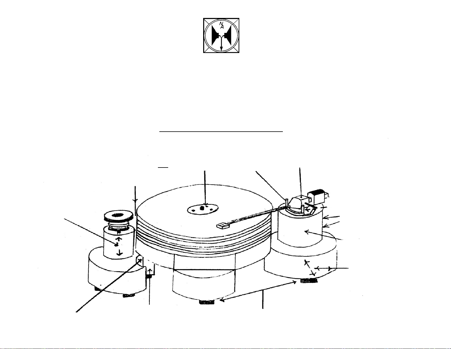
SPACEDECK INSTRUCTIONS
Place the turntable on a level surface. Half fill the bearing hole with oil. Carefully lower the
platter assembly into the bearing well centrally and allow to sink slowly under it’s own weight.
This can take several minutes. Level the turntable by the two adjusting feet. Place the motor up
to the platter and align the two motor pulley grooves to coincide with the two bottom grooves in
the platter by pushing the motor housing into the body up or down. If pushing down, do not push
from the top of the pulley as motor damage may result. Place the belt around the bottom grooves
of the platter and motor pulley. The bottom groove is 33 1/3 rpm and the top is 45 rpm.
Place the motor cut out groove by the static leg of the turntable without touching it and pull the
motor body away from the leg to leave a gap of 6mm between the top of the pulley and the
player. Always use the turntable with the mat on. The plastic cover is a dust cover only. Do not
touch the three caphead bolts on the top of the platter.
To start the turntable, give the platter a push by the thick rubber band. If pushed to fast, it will
adjust to the correct speed in a few seconds. To stop the platter, gently place your hand on the
thick rubber band.
Attach the cartridge to the arm and place the arm into the hole. The headshell should face directly
to the front when the arm is ‘parked’. Place the mat and an old record onto the platter. Position
the arm so that it sweeps the whole of the record before hitting the ‘stop’. Adjust the height and
level with the small spirit level on top of the headshell. Tighten the two grub screws in the arm
pillar. Align the cartridge and playing weight in the usual way. When using scales, place them
directly onto the mat, not on the record. The adjustment of the playing-weight is set by moving
the heavy bronze inner-weight. The bias is set by ear, but a rough guide is to lower the arm onto
the runout groove of the record. It should stabilize before running gently into the center of the
record. If the stylus moves quickly to the inside or outside of the record, the bias needs to be
increased or decreased.
Note: if unable to get the correct cartridge adjustment, the armboard satellite can be adjusted by
removing the platter and undoing the cap head bolt on the right side of the baseboard.
NOTTINGHAM ANALOGUE STUDIO
128 CORDY LANE, UNDERWOOD, NOTTINGHAM NG16 5FD
Design and Manufacture of Quality Audio Equipment
Telephone: +(44) (0) 1773 762947
Fax: +(44) (0) 1773 533566
V.A.T. REGISTRATION NO. 667 3729 92
SPACEDECK DIAGRAM
ADJUSTABLE
ARM BOARD
ARM
HEIGHT:
2 GRUB SCREWS
ARM PILLAR
ARM STOP
DO NOT
ADJUSTING FEET
ARM STOP
PULLEY TOP
TO PLATTER
PULLEY TOP
TO PLATTER
PULLEY TOP
TO PLATTER
CAPHEAD BOLTS
NON ADJUSTABLE
PULLEY TOP
TO PLATTER
STATIC LEG
ADJUSTABLE MOTOR
HOUSING TO ALIGN
PULLEY GROOVE TO
PLATTER GROOVE
MOTOR
CUTOUT

NOTTINGHAM ANALOGUE STUDIO
128 CORDY LANE, UNDERWOOD, NOTTINGHAM NG16 5FD
Design and Manufacture of Quality Audio Equipment
Telephone: +(44) (0) 1773 762947
Fax: +(44) (0) 1773 533566
V.A.T. REGISTRATION NO. 667 3729 92
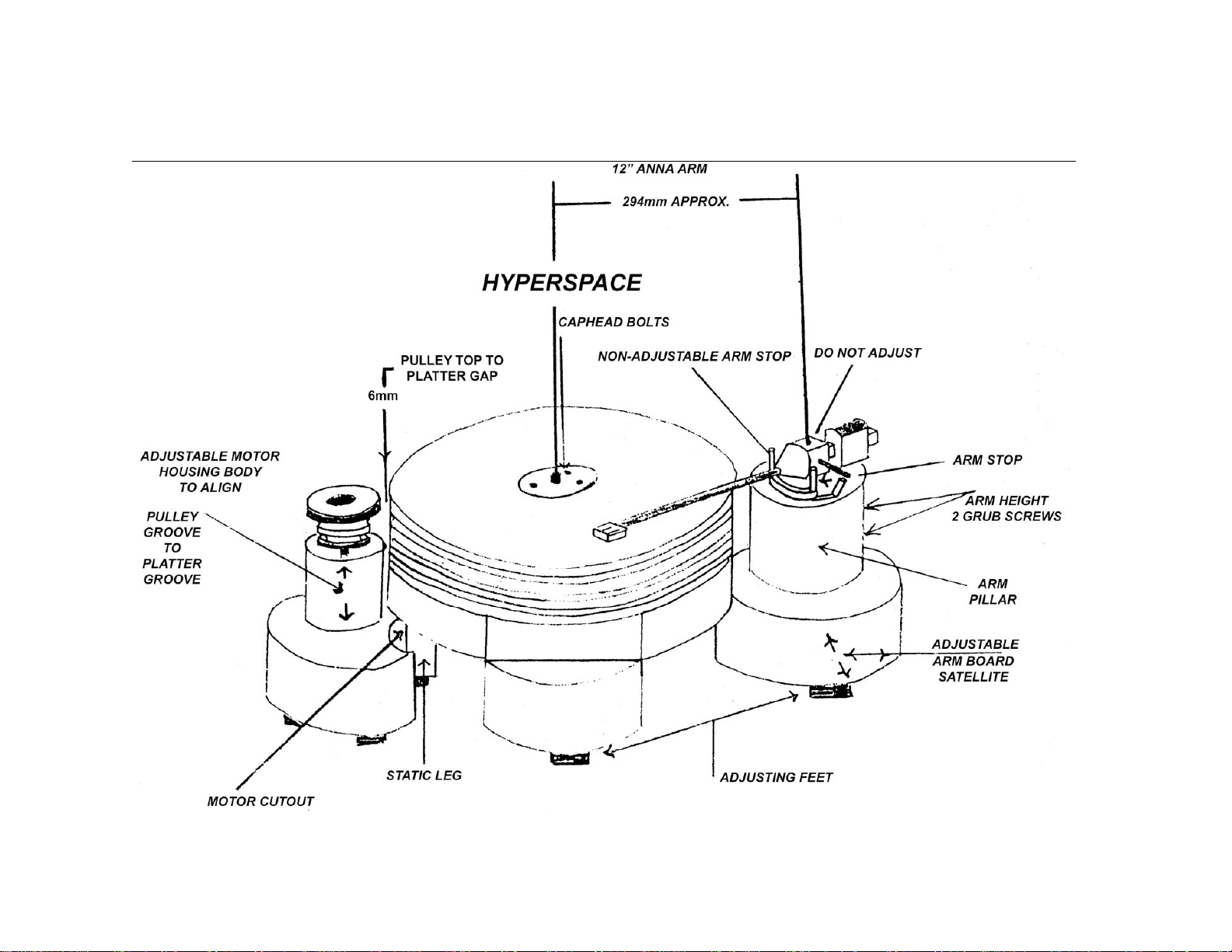
HYPERSPACE INSTRUCTIONS
Place the turntable on a level surface. Put two capfuls of oil into the bearing well. Carefully lower
the platter assembly into the bearing well centrally and allow to sink slowly under its own weight.
This can take several minutes. After placing the main platter into the bearing well fit the plastic
spacer over the spindle shaft, then gently lower the graphite top onto the main platter. Place the
second rubber band in the groove between the main platter and the graphite top/ Level the
turntable by the two adjusting feet.
Place the motor up to the platter and align the two motor pulley grooves to coincide with the two
bottom grooves in the platter by pushing the motor housing into the body up or down. If pushing
down, do not push from the top of the pulley as motor damage may result. Place the belt around
the bottom grooves of the platter and motor pulley. The bottom groove is 33 1/3 rpm and the top
is 45 rpm.
Place the motor cut out groove by the static leg of the turntable without touching it and pull the
motor body away from the leg to leave a gap of 6mm between the top of the pulley and the
player. Always use the turntable with the mat on. The plastic cover is a dust cover only. Do not
touch the three caphead bolts on the top of the platter.
To start the turntable, give the platter a push by the thick rubber band. If pushed to fast, it will
adjust to the correct speed in a few seconds. To stop the platter, gently place your hand on the
thick rubber band.
Attach the cartridge to the arm and place the arm into the hole. The headshell should face directly
to the front when the arm is ‘parked’. Place the mat and an old record onto the platter. Position
the arm so that it sweeps the whole of the record before hitting the ‘stop’. Adjust the height and
level with the small spirit level on top of the headshell. Tighten the two grub screws in the arm
pillar. Align the cartridge and playing weight in the usual way. When using scales, place them
directly onto the mat, not on the record. The adjustment of the playing-weight is set by moving the
heavy bronze inner-weight. The bias is set by ear, but a rough guide is to lower the arm onto the
runout groove of the record. It should stabilize before running gently into the center of the record.
If the stylus moves quickly to the inside or outside of the record, the bias needs to be increased or
decreased.
Note: if unable to get the correct cartridge adjustment, the armboard satellite can be adjusted by
removing the platter and undoing the cap head bolt on the right side of the baseboard.

NOTTINGHAM ANALOGUE STUDIO
128 CORDY LANE, UNDERWOOD, NOTTINGHAM NG16 5FD
Design and Manufacture of Quality Audio Equipment
Telephone: +(44) (0) 1773 762947
Fax: +(44) (0) 1773 533566
V.A.T. REGISTRATION NO. 667 3729 92
DAIS INSTRUCTIONS
Well done, you have found the instructions! Now, carefully unpack both boxes. OK – we know it
looks like a ‘kit’ to build a turntable. Put the plinth onto the surface you are going to use for your
turntable with the ‘U’ shape cut out facing away from you. Put the motor into the ‘U’ shape with
the lobe of the motor inside. Lift up the bearing chassis and you will find at the back a small ‘u’
shape cut out. This has to fit centrally around the motor, approximately 3mm away. With the
spirit level provided, level the chassis with the three leveling feet. Carefully remove the sealing
tape from around the bottom of the bearing. This will allow you to take the ‘male’ out of the
‘female’ part of the bearing. Half fill the bearing with the oil provided (do not worry if you slightly
over fill it). Gently lower the male spindle into the hole and let it settle slowly down for a few
minutes – it may take a long time to go right down, but it will reach its final level when the platter
is put on.
Before placing the platter onto the bearing, make sure the mating surfaces are clean. Then,
using the lifting handles provided, lower the platter very gently onto the bearing. Once the platter
has settled, check the level again with the spirit level on top of the platter. Unscrew the lifting
handles and gently place the graphite ‘mat’ on top of the platter. Place the drive belt around the
platter and motor (top groove for 45rmp, bottom for 33 1/3rpm). Now you can fit your arm in the
usual way. It is self-explanatory how to adjust the armboard ‘lobes’ with the tools provided.
Happy listening!

NOTTINGHAM ANALOGUE STUDIO
128 CORDY LANE, UNDERWOOD, NOTTINGHAM NG16 5FD
Design and Manufacture of Quality Audio Equipment
Telephone: +(44) (0) 1773 762947
Fax: +(44) (0) 1773 533566
V.A.T. REGISTRATION NO. 667 3729 92
ASSEMBLY INSTRUCTIONS FOR ‘HEAVY DUTY KITS’
Remove the arm from the turntable.
Position the turntable satellite over the edge of a table. With the standard Allen key, undo the two
headscrews under the armbase. Place the 25mm spacer in and re-connect the armbase to the
satellite using the longer bolts provided.
Position the centre adapter in the middle of the turntable and gently lower the graphite platter
onto the original platter. The damping ring is then placed in the groove between the original and
the new graphite platters.
Replace and set up the arm.
Happy listening.
PLEASE NOTE: Due to the nature of the platter material, you may often find small
imperfections in the top or bottom of the platter. This will make no difference to the function or
the sound.

NOTTINGHAM ANALOGUE STUDIO
128 CORDY LANE, UNDERWOOD, NOTTINGHAM NG16 5FD
Design and Manufacture of Quality Audio Equipment
Telephone: +(44) (0) 1773 762947
Fax: +(44) (0) 1773 533566
V.A.T. REGISTRATION NO. 667 3729 92
WAVE MECHANIC POWER SUPPLY
Why a power supply? But first, why an AC turntable motor?
Nottingham Analogue turntables excel by virtue of their almost elemental simplicity, relying as
they do on the fact that a rotating platter will continue to do so at absolutely constant speed
unless acted upon by outside forces. By coupling this steadily rotating mass to an arm base that
is stable around the axis of rotation of the platter, the result is a truly integrated unit.
By giving the platter adequate moment of inertia, the effects of any variability in outside forces are
minimized. However, the most important force, bearing friction, should if the bearing is correctly
made and lubricated remain essentially constant; hence, all that is required is to supply a small
amount of energy to the platter at a constant rate – just sufficient to counter the friction and
maintain a steady speed.
DC motors and their highly developed control systems may rightly dominate the small motor
market for “movement and placement” applications such as robotics, but are they what we need
in order to maintain this steady state? For this purpose, an AC synchronous motor backed by the
“mass” of the National Grid should be the answer. Unfortunately, although the laws of mechanics
show no sign of changing, electricity supplies are – and apparently always for the worse. There
are four main areas of concern.
1. Voltage variations
As a case in point, since “harmonizing” with the rest of the EC, the nominal UK domestic supply
voltage has fallen from 240V to 230V, but the permissible range of voltage has increased vastly,
now being from –6% (216.2V) to +10% (253V). This whole range will not be seen in any one
locality, but wide variations do occur between different areas.
For an AC synchronous motor, such voltage variations will not affect its overall speed, but will
affect its torque: not what we need for constant energy input (torque x speed = power). In
addition, the absolute voltage level has a very distinct effect on the dynamics and detail of the
music, with a clearly audible optimum voltage range. We need, then, to be able to optimize the
motor supply voltage and to hold it stable.
2. Frequency variations
These, by definition, will directly affect the speed of a synchronous motor. Supply frequency
variations are generally slow, but are easily demonstrated using an independent precision strobe
illuminator such as the “Zapper”.
Permissible variation in the UK is +/- 1% (6% equates to a semitone). Over 24 hours the
frequency must average exactly 50Hz to satisfy users of synchronous clocks, so that if the
frequency is slow at one point in the 24 hours, it must be fast at some other point as night follows
day (sometimes literally!). For a power supply, some slight adjustment of frequency is desirable
for pitch purposes but once set, it must remain stable.

3. Supply waveform
This is an aspect that has been becoming universally and insidiously more of a problem over the
years largely as a result of the “switched mode” power supplies that have generally supplanted
transformers in much modern electronic equipment.
The supply waveform does not now have a clean sinusoidal shape, but shows drastically clipped
peaks – the equivalent of adding numerous high order harmonics to the fundamental 50 or 60 Hz.
These can be shown to exist at significant levels far up into the audio frequency range, and even
if attenuated by damping in the drive belt will still feed through to the platter. We need to
synthesize a new clean waveform; “filtering” is not an answer.
4. Voltage spikes, and other “hash”
These are another part of the fallout from the volume and complexity of modern consumer
demands, and are sufficiently worrying to have provoked restrictive regulations on equipment
manufacturers. Our AC motor supply needs to be free of all such intrusions.
THE WAVE MECHANIC
The “Wave Mechanic” power supply addresses all of these issues, and provides a clean
waveform, stable in voltage and frequency even when run off voltages well below the permissible
level. The output voltage is pre-set internally to be in the optimum range, and there is a single
control on the front panel to allow minor adjustment of the frequency for pitch control. Other than
for this purpose it will probably remain untouched.
Both 50Hz and 60Hz version are available configured to suit local frequency and voltage.
For a Turntable speed reference to partner the “Wave Mechanic” power supply, the “Zapper”
hand-held battery-operated strobe illuminator is ideal. This is available in 50Hz and 60Hz
version, either with the power supply or separately for more general use.
The audible benefits of the power supply are very clear. Detail, dynamics and sound stage are all
much improved, but perhaps the most evident feature is the way that the whole pace and rhythm
of the music sound natural and true. Pitch stability is impeccable, giving complete confidence
and much deeper involvement in the musical performance.
The benefits should not be expected to replace those from upgrading the turntable, but rather to
complement them. Al of the Nottingham Analogue turntables will benefit, whether your current
one or your next upgraded one!
Specifications:
Supply voltage/frequency: Version for 230V/50Hz, 115V/60Hz, 100V/50Hz, 100V60Hz
Power consumption: 6.5W
Fuse: Ceramic HRC 5mm x 20mm T250mA (230V), T500mA (115V and 100V)
Output frequency: 50Hz or 60Hz (depending on model) with control in center position.
Case Dimensions: (H x W x D) 2.55” x 4.13” x 11.22”
Weight: (w/ packaging) 5.6 lbs.

NOTTINGHAM ANALOGUE STUDIO
128 CORDY LANE, UNDERWOOD, NOTTINGHAM NG16 5FD
Design and Manufacture of Quality Audio Equipment
Telephone: +(44) (0) 1773 762947
Fax: +(44) (0) 1773 533566
V.A.T. REGISTRATION NO. 667 3729 92
Pulley Installation
An adjustment has been made to the packing of Nottingham’s turntables to ensure that
the motor/pulley assembly can better withstand the rigors of shipping in the United
States. Follow these steps to properly affix the pulley to the motor:
1. Locate the pulley (fig. 1)
2. Locate the motor (fig. 2)
3. Slide the hole in the bottom of the pulley (fig. 3) over the post at the center of the
motor, and press down until the pulley stops.
When the turntable is spinning, if you notice rubbing at the bottom of the pulley, simply
pull up on the pulley to eliminate any contact with the motor housing.
Figure 1
Figure 2
Figure 3
Completed motor assembly

NOTTINGHAM ANALOGUE STUDIO
128 CORDY LANE, UNDERWOOD, NOTTINGHAM NG16 5FD
Design and Manufacture of Quality Audio Equipment
Telephone: +(44) (0) 1773 762947
Fax: +(44) (0) 1773 533566
V.A.T. REGISTRATION NO. 667 3729 92
Rega Tonearm Instructions
With the cartridge fitted and aligned using the alignment
protractor supplied, ensure that the bias adjustment
slider is set to zero. Screw the balance weight along its
shaft until the stylus is ‘floating’ just 1mm clear of the
record.
The recommended tracking force can now be applied by
rotating the balance weight so that it moves toward the
front of the arm. One half-turn gives 1g of tracking force.
The green plastic plugs on the weight can be used as a
visual aid to achieve this. Always use a force that
corresponds to the upper limit of the cartridge maker’s
recommended range.
Set the bias adjustment slider to the same number as
the tracking force control, i.e.
1 ½g tracking force=1 ½ on the bias slider.
This manual suits for next models
6
Table of contents
Other NOTTINGHAM ANALOGUE STUDIO Turntable manuals


