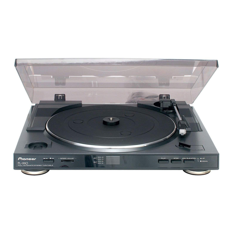
Pioneer PL-115D User manual

STEREO
TURNTABLE
PL-115D
.
KCT
OPERATING
INSTRUCTIONS
a
KUT
WARNING:
TO
PREVENT
FIRE
OR
SHOCK
HAZARD,
—
DO
NOT
EXPOSE
THIS
APPLIANCE
TO
RAIN
OR
|-—4
————
—
.
_@PIONEER——___wosTuRe.
"|

The
PL-115D
is
prelubricated
at
the
factory,
but
the
oil
may
have
dried
up
during
shipment,
so
before
use
apply
a
few
drops
of
the
accessory
oil
as
described
on
page
10.
The
PL-115D
is
a
high
precision
belt
drive
turntable
designed
for
incorporation
into
a
component
type
stereo
music
system.
It
is
recommended
that
you
read
these
Operating
Instructions
completely
before
using
the
turn-
table.
CONTENTS
PL-115D
Features
Attaching
the
Cartridge
.
Assembly
Steps
.........+
Component
Locations
Tonearm
Adjustments
............
Stereo
Amplifier
Connections
......
Conditions
Frequently
Mistaken
for
Malfunction
.....
Specifications
......
PL-115D
FEATURES
Precision
Belt
Drive
with
4-pole
Synchronous
Motor
Stable
rotation
of
the
30cm
diecast
aluminum
alloy
platter
is
maintained
by
the
carefully
engineered
4-pole
synchronous
motor
and
belt
drive
system,
The
smooth
running
of
the
motor
is
unaffected
by
fluctuations
in
line
voltage
and
load,
while
even
the
slightest
vibrations
from
the
motor
are
absorbed
by
the
poly-
urethane
belt.
High
performance
is
exemplified
by
the
0.07%
(WRMS)
wow
and
flutter,
and
SOdB
(JIS)
signal
to
noise
ratio.
Speed
Detector
Type
Auto
Return
Mechanism
Faulty
auto
return
is
avoided
by
employing
a
speed
detector
system
in
the
mechanism
to
assure
perfect
operation
at
the
end
of
the
record.
By
pressing
the
RETURN
button
the
auto
return
machanism
can
also
be
used
to
interrupt
a
record
during
play,
at
which
time
the
tonearm
is
raised
and
returned
to
the
arm
rest
without
risk
of
damage
to
the
record.
High
Sensitivity
S-shaped
Tonearm
The
tonearm
gimbal
incorporates
high
precision
angular
contact
bearings,
whose
low
vibration
and
friction
ensure
high
sensitivity
together
with
long
term
reliability.
Anti-skating
and
lateral
balance
controls
are
included
for
optimum
performance
with
high
com-
pliance
cartridges
and
light
tracking
forces,
and
the
direct
readout
of
the
tracking
force
is
especially
convenient
when
replacing
the
cartridge.
Sophisticated
Cabinet
Styling
The
baseplate
is
made
from
mineral
solid,
a
new
high
density
material
which
combines
excellent
acoustic
absorption
properties
to
prevent
resonance
with
high
strength
and
attractive
finish.
In
addition
the
elegant
wood
grain
finish
of
the
cabinet
ideally
matches
the
high
quality
engineering
of
the
PL-115D.
Numerous
Additional
Features
A
host
of
additional
features
enhance
the
convenience
and
performance
of
the
PL-115D.
Among
these
are
a
lightweight,
high
rigidity
aluminum
headshell,
low
capacitance
output
cord,
and
an
oil-damped
tonearm
elevation
mechanism
to
protect
valuable
records
and
stylus.
The
interior
of
the
cabinet
is
lined
with
aluminum
foil
to
screen
out
external
electrical
noise
which
is
often
picked
up
from
other
household
appliances,
while
motor
and
external
vibrations
are
also
isolated
by
the
double
suspension
design.

PIONEER
ATTACHING
THE
CARTRIDGE
Moving magnet
(MM),
moving
coil
(MC)
and
induced
magnet
(IM)
are
the
main
cartridge
types.
Although
all
of
these
can
be
used
with
the
PL-115D,
select
cartridges
with
weights
between
4—10
grams.
Refer
to
the
cartridge
operating
instructions
for
connection
and
handling.
Since
the
tonearm
of
the
PL-115D
is
a
universal
type,
your
optional
cartridge
with
standard
type
headshell
can
be
attached
with
no
problem.
Install
the
cartridge
to
the
headshell
according
to
the
following
steps.
1.
When
attaching
cartridge
to
the
accessory
head-
shell,
use
the
headshell,
screwdriver,
overhang
gauge,
screws,
nuts
and
washers
supplied
in
the
accessory
box
(Fig.
4).
2.
Connect
headshell
lead
wires
to
the
cartridge.
Observe
lead
wire
color
coding
as
follows.
White
L
(left
channel)
Blue
LG
(left
channel
ground)
Red
R
(right
channel)
Green
RG
(right
channel
ground)
3.
Fit
cartridge
to
headshell
(Fig.
1),
but
do
not
tighten
the
mounting
screws
yet.
4.
Set the
headshell
into
the
accessory
overhang
gauge
as
shown
in
Fig.
2.
Adjust
the
cartridge
position
so
that
the
stylus
tip
is
aligned
with
the
gauge
line.
Finally,
tighten
the
cartridge
mount-
ing
screws,
:
5.
Install
headshell
on
tonearm
according
to
Fig.
8
on
next
page.
If
your
cartridge
weighs
over
8.5g,
insert
the
sub
weight
into
the
end
of
the
tonearm
shaft.
Refer
to
Fig.
3.
ACCESSORIES
The
accessory
box
contains
the
following
parts.
e's
oi
CARTRIDGE
Fig.
1
Fig.
2
Fig.
3
COUNTERIRGIONT
OVERHANG
GAUGE
45
rpm
ADAPTOR:
SCREWDRIVER
5
HEADSHELL
LATERAL
WEIGHT
il
x
|
SUB
WEIGHT
‘SCREWS-6,
NUTS-2
WASHERS-2
]
Fig.
4

ASSEMBLY
STEPS
1,
REMOVE
TONEARM
PACKING
The
tonearm
is
protected
by
styrofoam
cushioning
material
during
shipment.
Peel
off
the
tape
and
while
taking
care
not
to
exert
unnecessary
force
on
the
tonearm,
remove
the
packing
material
(Fig.
5).
2.
TAKE
OUT
CLAMP
SCREW
To
protect
from
possible
damage
in
transit,
the
chassis
is
secured
to
the
base
plate
with
the
5
screws
(Fig.
6).
These
must
be
removed
before
assembling
the
turntable.
The
chassis
will
then
float
on
its
vibration-absorbing
spring
suspension.
3.
INSTALL
TURNTABLE
PLATTER
Use
the
two
finger
holes
in
the
platter to
lift
it
and
carefully
place
it
onto
the
center
shaft
(Fig.
11).
4.MOUNT
THE
BELT
ON
THE
MOTOR
PULLEY
Set
the
speed
select
lever
to
33
position,
Pulling
the
ribbon
attached
to
the
drive
belt,
pass
the
belt
through
the
belt
guide
and
around
the
smaller
diameter
(the
upper
portion)
of
the
motor
pulley
(Fig.
7).
After
the
belt
has
been
properly
positioned
on
the
motor
pully,
remove
the
ribbon
and
place
the
rubber
mat
and
decorative
ring
(see
Fig.
11).
5.
INSTALL
HEADSHELL
Insert
the
headshell
into
the
tonearm
sleeve
and
lock
it
in
place
by
turning
the
locking
collar
(Fig.
8).
6.
MOUNT
COUNTERWEIGHT
Fit
the
counterweight
onto
the
rear
end
of
the
tonearm
and
turn
it
2
or
3
times
in
the
direction
of
the
arrow
(Fig.
9).
COUNTERWEIGHT.
Fig.
9
TONEARM
PACKINGS
TAKE
OFF
TAKE
OFF
Zz,
Fig.
5
PHILLIPS
SCREWDRIVER
MOTOR
PULLEY
RIBBON
DRIVE
BELT
BELT
GUIDE
ea
\
Fig.
7
LOCKING
COLLAR
Fig.
8

7.
ATTACH
LATERAL
WEIGHT
18
to
23mm
Use
the
accessory
screwdriver
to
fix
the
lateral
weight
on
its
bar
and
adjust
for
18—23mm
spacing
between
the
lateral
weight
and
tonearm
(Fig.
10).
Readjustment
is
not
required,
even
after
replacing
the
cartridge.
eZ
‘ACCESSORY
SCREWDRIVER
LATERAL
WEIGHT
Fig.
10
COMPONENT
LOCATIONS
DECORATIVE
RING
RUBBER
eed
it
TURNTABLE
PLATTER
ORIVE
BELT
UTPUT
CORDS
LD
ROUND
WIRE
BELT
GUIDE
“AC
CORD
SPEED
SELECT
OUNTERWEIGH™
LEVER
oer,
BASE
PLATE
“ANTI-SKATE
KNOB
“ARM
REST
CENTER
SHAFT.
RETURN
BUTTON
ARM
ELEVATION
LEVER
HEADSHELL
Fig.
11

TONEARM
ADJUSTMENTS
HEADSHELL
ARM
PIPE
CARTRIOGE
LOCKING
COLLAR
TONEARM
PARTS
After
correctly
assembling
the
tonearm,
perform
the
following
adjustments.
Do
not
connect
the
AC
cord
to
the
mains
outlet
until
adjustments
have
been
completed.
HORIZONTAL
BALANCE
1,
Set
ANTI-SKATE
knob
to
0
(Figs.
12
and
14).
2.
Uncover
the
stylus.
3.
Set
the
arm
elevation
lever
to
DOWN.
4.
Release
the
arm
clamp
and
disengage
the
tone-
arm
from
the
arm
rest.
Since
the
tonearm
moves
freely
at
this
time,
take
care
not
to
damage
the
stylus.
5.
Tum
the
counterweight
and
adjust
so
that
the
tonearm
becomes
level
with
the
platter,
without
slanting
either
toward
the
headshell
or
counter-
weight.
Figs.
13-A
and
13-B
show
the
tonearm
in
unbalanced
conditions.
NOTE:
If
the
cartridge
is
too
heavy
to
adjust
by
this
means,
attach
the
sub
weight
agcording
to
Fig.
3
on
page
3.
6.
Return
the
tonearm
to
the
arm
rest
and
engage
the
clamp.
7.
Since
the
tonearm
is
balanced,
the
tracking
force
is
zero,
so
turn
the
tracking
force
ring
at
the
front
of
the
counterweight
(taking
care
not
to
disturb
the
counterweight)
to
align
the
0
with
the
reference
line
(Fig.
14).
TRACKING
FORCE
Turn
the
counterweight
and
align
the
indication
on
the
tracking
force
ring
which
corresponds
to
the
recommended
tracking
force
of
the
employed
cartridge
with
the
reference
line
(Fig.
15).
The
ring
is
divided
into
0.5
gram
divisions
and
1
rotation
is
equivalent
to
4
grams
tracking
force.
LATERAL
WEIGHT
ARM
REST
TRACKING
FORCE
RING
ARM
ELEVATION
ANTI-SKATE
Fig.
12
KNOB
TRACKING
FORCE
RING.
Fig,
14
REFERENCE
LINE
“
1
Fig.
15

ANTI-SKATING
Set the
ANTI-SKATE
knob
to
the
same
value
as
the
tracking
force
of
the
employed
cartridge.
For
example,
if
the
tracking
force
is
2
grams,
set
this
knob
to
2
(Fig.
16).
Fig.
16
STEREO
AMPLIFIER
CONNECTIONS
The
phono
inputs
of
the
amplifier
to
which
the
turntable
should
be
connected
must
be
chosen
in
accordance
with
type
of
phono
cartridge
to
be
used.
e@
With
moving
magnet
or
induced
magnet
type
cartridge:
Connect
to
the
PHONO
MAG
inputs
of
the
amplifier.
@
With
low-output
moving
coil
type
cartridge:
Connect
to
the
PHONO
MC
inputs.
If
these
are
not
provided
on
your
amplifier,
a
step-up
transformer
will
be
required.
NOTE:
Refer
to
the
cartridge
instruction
manual
for
further
detail.
In
either
case,
connect
the red
output
plug
from
the
turntable
to
the
amplifier’s
right
channel
input
and
the
white
plug
to
the
left
channel
input.
The
third
black
wire
(the
ground
wire)
with
the
split
plug
can
be
connected
to
the
GROUND
terminal
of
your
amplifier
(Fig.
17).
Do
not
forget
to
make
this
connection,
because
it
is
vital
for
avoiding
hum
and
noise.
DUST
COVER
It
is
convenient
to
install
the
dust
cover
from
the
rear
of
the
tumtable
as
shown
in
Fig.
18.
Hold
the
cover
at
the
bottom
and
insert
its
hinges
into
the
sockets
of
the
turntable
base.
To
remove
the
dust
cover,
again
grasp
it
as
shown
in
Fig.
18
and
pull
it
straight
upward.
INSTALLATION
HINTS
PL-115D
__Ground
wire
PHONO
Lchennel
STEREO
AMPLIFIER
Fig.
17
Pay
attention
to
the
following
points
when
selecting
a
location
for
the
PL-115D.
e
The
place
must
be
well-ventilated
and
free
from
e
The
turntable
should
be
placed
as
far
from
the
humidity
and
dust.
speaker
system
as
possible,
and
not
too
close
to
the
power
transformer
of
the
amplifier.
©
Select
a
surface
that
is
firm
and
level.
e@
Avoid
exposure
to
direct
sunlight
or
other
sources
of
heat.

PANEL
FACILITIES
HEADSHELL
STAND
A
spare
headshell
can
be
stored
in
this
stand.
Align
the
headshell
pins
with
the
stand
grooves
and
insert.
Observe
that
the
headshell
length
is
not
greater
than
the
height
of
the
dust
cover,
This
stand
can
also
be
used
for
storing
the
45rpm
adaptor.
SPEED
SELECT
LEVER
Either
of
the
two
speeds,
33-1/3rpm
or
45rpm,
can
be
selected
by
this
lever.
Only
change
the
position
while
the
turntable
is
rotating.
RETURN
BUTTON
To
stop
playback
before
the
end
of
a
record,
press
this
button;
the
tonearm
returns
automatically
to
the
arm
rest
then
the
power
is
switched
off.
@
PIONEER
AUTOMATIC
RETURN
STEREO
TURNTABLE
PL-II5D
RETURN
BUTTON
ARM
ELEVATION
LEVER
Setting
this
lever
to
UP
raises
the
tonearm,
while
setting
it
45RPM
ADAPTOR
to
DOWN
lowers
the
tonearm
gently
onto
the
record.
A
4Srpm
record
adaptor
is
supplied
in
the
accessory
box,
This
device
is
convenient
for
cuing
any
position
on
the
which
permits
45rpm
EP
records
with
large
center
holes
record
without
fear
of
scratching
the
record
surface.
to
be
played.
DOWN
POSITION

————
ARM
ELEVATION
Arm
elevation
may
require
adjustment
according
to
cartridge
height.
If
necessary,
use
the
accessory
screw-
driver
to
loosen
the
setscrew
and
adjust
(see
figure).
ACCESSORY
SCREWDRIVER
‘ARM
REST
The
arm
rest
supports
the
tonearm,
which
should
be
secured
by
the
arm
clamp
when
not
in
use.
Before
raising
the
tonearm,
be
sure
to
release
the
clamp.
SL
a
a
a
RS
eee
|
ONE
ER
OPERATION
1.
Place
the
record
to
be
played
on
the
turntable
platter.
2.
Remove
the
stylus
cover
and
disengage
the
arm
clamp.
8.
After
setting
the
ARM
ELEVATION
lever
to
UP,
move
the
tonearm
from
the
arm
rest.
(The
turntable
platter
will
begin
to
rotate.)
.
Set the
SPEED
select
lever
to
the
correct
speed
according
to
the
record
to
be
played.
5.
Position
the
tonearm
above
the
desired
portion
of
the
record
by
hand.
6.
Move
the
ARM
ELEVATION
lever
to
DOWN.
The
stylus
will
be
gently
lowered
onto
the
record.
7.
Adjust
the
volume
and
tone
controls
of
the
stereo
amplifier
as
desired.
8.
When
the
record
is
finished,
the
tonearm
returns
to
the
arm
rest
automatically
and
the
power
is
cut
off.
It
is
advisable
to
replace
the
stylus
cover
for
protection
whenever
the
turntable
is
not
in
use.
NOTE:
Before
playing
the
next
record,
be
sure
to
re-set
the
ARM
ELEVATION
lever
to
the
UP
position
to
avoid
damage.
>
e
If
you
wish
to
stop
play
in
the
middle,
simply
push
the
RETURN
button
(The
tonearm
will
return
to
the
arm
rest,
then
the
power
will
be
switched
off
).
To
Take
Full
Advantage
of
the
Arm
Elevation
Lever
The
ARM
ELEVATION
lever
is
particularly
con-
venient
when
you
wish
to
choose
a
particular
track
from
an
LP
record.
e
If
you
move
the
tonearm
with
the
ARM
ELEVATION
lever
set
to
DOWN,
take
care
not
to
damage
the
stylus
point.
OPERATING
PRECAUTIONS
@
Keep
stylus
and
records
clean.
Use
a
stylus
brush
to
clean
the
stylus
and
a
good
quality
record
cleaner
to
clean
the
records
each
time
before
and
after
playing.
e
Avoid
exerting
unnecessary
force
on
the
tone-
arm,
When
changing
headshells,
set
the
tonearm
in
the
arm
rest
and
engage
the
clamp.
e
Take
care
not
to
impart
vibration
to
the
turntable
while
a
record
is
playing.
Record
and
stylus
can
be
damaged.
e@
Never
touch
the
SPEED
select
lever
if
the
turntable
is
stationary.
The
speed
can
be
chang-
ed
only
while
the
turntable
is
rotating.
e
Never
obstruct
the
turntable
by
hand
while
it is
rotating.
This
may
cause
damage.

CARE
OF
YOUR
TURNTABLE
CLEANING
CABINET
Use
a
polishing
cloth
or
a
soft
dry
cloth
to
clean
dust
from
the
cabinet
and
dust
cover.
Do
not
use
household
waxes,
solvents
or
sprays
on
or
near
the
turntable
as
they
can
mar
the
finish.
LUBRICATION
Mechanical
noise
or
wow
and
flutter
usually
result
from
a
lack
of
lubricant
in
the
rotating
parts.
Lubricate
the
following
point
at
least
once
every
two
months
for
normal
use,
and
two
to
three
times
if
the
turntable
is
used
very
frequently.
Before
applying
oil
to
the
turntable,
remove
the
turntable
platter
as
follows:
1.
Remove
the
dust
cover
as
described
in
“DUST
COVER”
on
page
7.
2,
Return
the
tonearm
to
the
arm
rest
and
clamp
it,
then
protect
the
stylus
tip
with
the
stylus
cover,
3.
Remove
the
drive
belt
from
the
motor
pulley
with
your
fingers
(Refer
to
Fig.
7
on
page
4).
4.
Lift
the
turntable
platter
straight
up
by
inserting
fingers
and
thumb
into
the
two
openings
(Fig.
19).
If
the
platter
does
not
come
away
easily,
try
jerking
it,
but
take
care
not
to
damage
any
part
of
the
turntable.
5.
Apply
one
or
two
drops
of
the
accessory
oil
to
the
lubricating
hole
(Fig.
20),
being
careful
not
to
get
oil
on
parts
such
as
the
motor
pulley,
belt,
or
inner
rim.
NOTE:
If
oil
should adhere
to
the
motor
pulley,
inner
rim,
or
are
vette
wipe
it
off
with
a
cloth
moistened
with
pure
alcohol.
Caution:
Never
use
other
solvents.
10
oe
Fig.
20

CONDITIONS
FREQUENTLY
MISTAKEN
FOR
MALFUNCTION
If
no
sound
is
obtained
from
the
speakers
after
assembling
this
turntable,
please
check
the
connections
and
operation
of
the
other
components
as
follows:
(a)
internal
connection
of
headshell
(e.g.
terminal
tips,
lead
wire
..)
(b)
attachment
of
locking
sleeve
(c)
output
cord
connections
(d)
speaker
wire
connections
(e)
amplifier
settings
(e.g.
VOLUME,
FUNCTION,
TAPE
MONITOR,
POWER
switch
..
)
SYMPTOM
DIAGNOSIS
AND
REMEDY
Turntable
does
not
Check
(a)
or
(b)
and
correct
the
condition
rotate
SUSPECTED
SOURCES
OF
NOISE
(a)
AC
cord
is
not
connected
to
AC
outlet
)
Drive
belt
is
disconnected
or
loose
(b}
Incorrect
turntable
Correct
the
conditions
stated
in
(a)
and
(b)
speed
Speed
select
lever
is
incorrectly
set
(b)
Drive
belt
is
incorrectly
fitted
Motor
pulley
and
belt
are
dirty
Wipe
the
motor
pulley
and
belt
clean
with
a
soft
cloth
dampened
with
pure
alcohol
Contact
to
Pioneer
Authorized
Service
Station
d
The
frequency
of
your
power
supply
does
not
suit
the
PL-115D
Correct
the
conditions
stated
in
(a),
(b),
(c),
(d)
or
(e)
Poor
connection
of
shielded
wire
(b)
Jack
connection
is
loose
(c)
Line
cord
of
fluorescent
lamp
passes
near
the
shielded
wire
{d)
Poor
grounding
{e)
Shielded
wire
is
running
near
the
power
transformer
of
the
amplifier
(f)
Ham
transmitting
station
or
TV
transmitting
station
is
near
your
house
Hum
or
buzz
(Reversing
the
AC
connections
may
occasionally
eliminate
hum)
In
the
case
of
(f),
report
it
to
an
official
authority
Poor
tone
quality,
noise,
(a)
Stylus
is
worn
Check
(a)
through
(e)
and
correct
the
condition
unclear
treble
(b)
Record
is
worn
(c)
Dust
adhering
to
stylus
(4)
Stylus
is
improperly
mounted
(e)
Stylus
pressure
is
not
correct
(f)
The
TREBLE
level
of
the
amplifier
is
too
high
Lower
the
TREBLE
level
Increase
the
distance
or
rearrange
the
installation
of
the
unit
and
speakers
(installing
the
turntable
on
a
firm,
solid
stand
may
alleviate
this
problem)
Do
not
enhance
the
BASS
sound
level
excessively
Howling
(a)
Distance
between
the
turntable
and
the
speakers
is
too
short
(b)
The
tumtable
or
speakers
sup-
ports
are
unstable
(c)
Clamping
screws
are
not
removed
|
Take
out
the
clamping
screws
according
to
Fig.
6
yet
‘on
page
4
a4

Ee
a
[ONES
SPECIFICATIONS
MOTOR
AND
TURNTABLE
Motor
Turntable
drive
.
Speed
Wow
and
flutter
.
SIN...
. »
4-pole
synchronous
Belt-driven
.
Two
speeds:
33-1/3rpm,
45rpm
0.07%
(WRMS)
or
less
.
.
50dB
(JIS)
or
more
(using
Pioneer
cartridge
model
PC-135)
Turntable
platter...
...........0006
30cm
diam.
aluminum
alloy
Moment
of
inertia
...........
135kg-cm?
(including
rubber
mat)
TONEARM
Tonearm
type
..........0005
Static-balance,
S-shaped,
pipe
arm
Effective
arm
length
.
.
.»
221mm
Tracking
error
..
+3°~—1°
Overhang
.
--15.5mm
Usable
cartridge
weight
.
4g
(min.)
~
10g
(max.)
(For
cartridge
weighs
over
8.5g,
attach
the
sub
weight)
SUBFUNCTIONS
Automatic
return
tonearm
system
Anti-skating
force
control
Plug-in
type
headshell
Oil-damped
arm
elevator
Hinges
(Free-adjustable)
Lateral
balancer
MISCELLANEOUS
Power
requirements
Power
consumption
Dimensions
...........--.-+
440(W)
x
362(D)
x
159(H)
mm
17-5/16(W)
x
14-1/4(D)
x
6-1/4(H)
in.
.»
6kg,
13
Ib
3
oz,
-
AC
120V,
60Hz
Weight
ACCESSORIES
Headshell
.
.
Accessory
oil
.
Overhang
gauge
45rpm
adaptor
.
Screwdriver
..
Sub
weight
..
Cartridge
mounting
screws
.
.
Cartridge
mounting
nuts
.
.
Cartridge
mounting
washers
.
Operating
instructions
HNNaewoweonaw
NOTE:
,
Specifications
and
design
subject
to
possible
modification
without
notice
due
to
improvements.
<76A02F53F>
PIONEER
ELECTRONIC
CORPORATION
4-1,
Meguro
1-Chome,
Meguro-ku,
Tokyo
153,
Japan
U.S.
PIONEER
ELECTRONICS
CORPORATION
75
Oxford
Orive.
Moonachie.
New
Jersey
07074.U.S.4.
PIONEER
ELECTRONIC
(EUROPE)
NV.
Luithegensteenweg
no.
9,
2030
Antwerp,
Belgium
PIONEER
ELECTRONICS
AUSTRALIA
PTY.
LTD.
178-184
Boundary
Rosa,
Braeside,
Victoria
3195,
Australia
Printed
in
Japan
<PRB-025-0)
Table of contents
Other Pioneer Turntable manuals

Pioneer
Pioneer PL-L70 User manual

Pioneer
Pioneer PL-4000 User manual

Pioneer
Pioneer PL-12D User manual

Pioneer
Pioneer PL-L70 User manual

Pioneer
Pioneer PL-470 User manual

Pioneer
Pioneer CDJ-2000NXS2 User manual

Pioneer
Pioneer PL-12D User manual

Pioneer
Pioneer PL-7 User manual

Pioneer
Pioneer PL-550 User manual

Pioneer
Pioneer PL-55DX User manual

Pioneer
Pioneer PL-X505 User manual

Pioneer
Pioneer LD-V4300D User manual

Pioneer
Pioneer PL-570 User manual

Pioneer
Pioneer PL-15D-II User manual

Pioneer
Pioneer PL-Z94 User manual

Pioneer
Pioneer DEH-P1Y User manual

Pioneer
Pioneer LD-1100 User manual

Pioneer
Pioneer PL-L50 User manual

Pioneer
Pioneer DEH-2790MP User manual
Pioneer
Pioneer RX-510 User manual