Operating Instructions
Introduction
Thank you for purchasing the Nova Vise™. We believe it is the best fly
tying vise available anywhere. It has been designed and manufactured
by fly fishermen for fly fishermen. Nova Concepts uses the best materi-
als available and completes the entire manufacturing process here in
Colorado. We carefully inspect all of our vises to ensure you are pur-
chasing the finest vise money can buy. Its rugged construction and
unique design allow for adjustments that no other vise can match. Nova
Vise™ operates differently from other vises so it is essential that you
read these instructions with the vise in front of you. Again, thank you for
purchasing Nova Vise™ and we wish you a lifetime of fly tying enjoyment.
Table Clamp Set-up
Once you have unpacked your Nova Vise™ place it on your tying table.
Notice that the vise head is folded down for storage and shipping pur-
poses. Leave it this way for now. Loosen the Post Clamping Knob (4) on
the upper jaw of the table clamp to remove the upper assembly of the
vise.
Set the two assemblies (table clamp & vise assembly) on your fly tying
table. Make sure your table is strong and has at least 2” of overhang for
attaching the Nova Vise™. The clamping jaws will accommodate a table
up to 3” thick. The table clamp is a “bar clamp” design which has a
coarse and fine adjustment. The coarse adjustment is the sliding lower
jaw that rides on the square grooved post. The fine adjustment is the
screw and swivel foot which is tightened via the large brass knob.
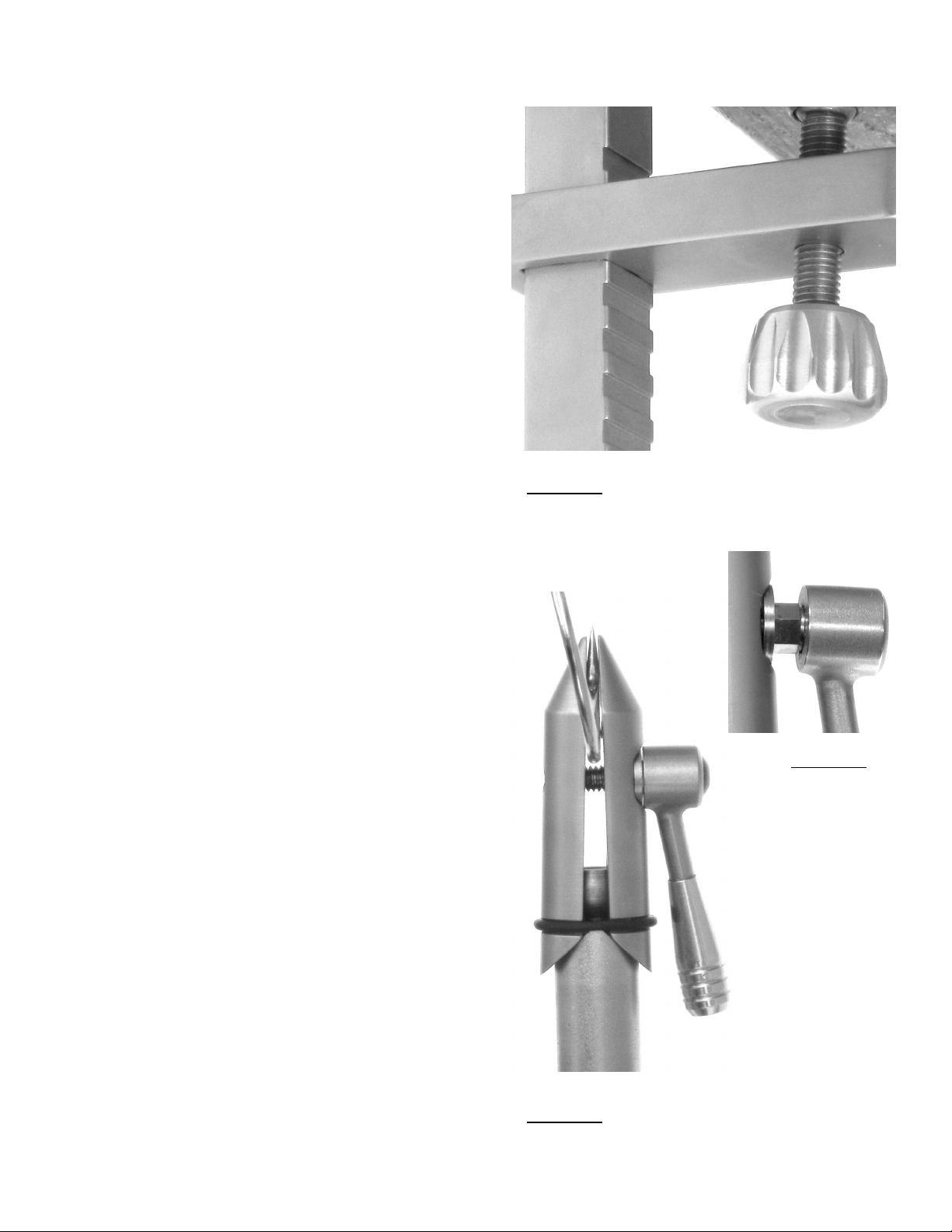
To attach the Nova Vise™ to your table, lower the Lower Clamping Jaw
(11) to the bottom of the Grooved Square Post(9). Place the jaws over
the edge of your table with the square post resting against the table
edge. Slide the Lower Clamping Jaw up the Grooved Square Post until
the Clamping Swivel Foot(10) contacts the table. Let the Lower Clamp-
ing Jaw drop slightly at an angle until it engages a groove. Then tighten
the Fine Adjustment Knob while holding the lower jaw in the groove
Figure 2. This is usually a two-handed operation. Pulling downward on
the brass knob may assist you with clamping jaw engagement in the
groove. Tighten the Fine Adjustment Knob until clamping on your table
is sufficient. Use caution as you may be able to generate tremendous
force and damage your table! Always ensure there are at least a few
threads between the Lower Clamping Jaw and Clamping Swivel Foot to
allow for effective clamping.
For those of us who have lost our grip over the years, you may wish to
use a 17mm box-end wrench to further tighten the clamp by slipping it
carefully over the brass knob. Only ¼ to ½ a turn is recommended to
get a really tight fit. Be careful not to damage your table!
Nova Vise™ Set-up
Place the round post of the vise assembly into the Upper Clamping Jaw
(8) of the table clamp. Adjust the height of the vise as you wish and
firmly tighten the Post Clamping Knob (4) to hold the vise assembly in
place.
Grasp the Nova Vise™ head and rotate it up to about 45° as in Figure 1.
Notice that there is considerable resistance due to the “drag brake” in
the Upper Jaw Clamp(1). The amount of drag is adjustable by rotating
the hex bolt in the clamp however we don’t recommend you make any
adjustments until you have used the vise for awhile. We find this degree
of resistance works for most tiers.
US Patent # 7,566,022B1
NOVA VISE
TM
Nova Concepts Incorporated, P.O. Box 233, Lake George, CO 80827 USA
Jaw Adjustment
Nova Vise™ jaw adjustment is dramatically different from any other vise!
The jaws are a “free-floating” design so the jaw to hook contact surfaces
can be independently adjusted to accommodate any hook size or hook
geometry. This is accomplished by changing the “gap” and geometry
between the vise jaws.
Figure 3 shows a tapered gap adjustment: wide at the rear near the O-
ring and narrow at the tip.
If you grip the bend or shank of the hook, where the wire is at full diame-
ter, use a “parallel” geometry where the gap is the same front and rear.
If you grip the hook near the barb or point, where the wire may flatten,
use a “tapered” geometry. This choice gives you maximum grip with a
minimum of force.
The gap and geometry are adjusted by the Geometry Adjustment Knob
(2) with Lock Ring(3) at the rear of the Nova Vise™.
To adjust the geometry of the Vise Jaws(5), begin opening the Vise Jaws
slightly by turning the Clamping Lever(6) counter-clockwise. Loosen the
Lock Ring and rotate the Geometry Adjustment Knob in either direction.
Notice the change in jaw gap at the rear of the jaws near the O-ring.
This fully-floating design is a major advantage because it allows for maxi-
mum contact between the jaws and hook without physically bending any
part of the Nova Vise™. This variable geometry jaw will work for your
smallest midge and largest saltwater pattern.
Post Clamping
Knob(4)
Figure 1
Upper Clamping
Jaw (8)
Drag Clutch Knob
(7)
Vise Jaws
(5)
Upper Jaw Clamp
with Integrated
Drag Brake(1) Clamping Lever
(6)
Geometry
Adjustment Knob
(2) with Lock Ring
(3)
Fine Adjustment
Knob (12)
Lower Clamping
Jaw (11)
Clamping Swivel
Foot (10)
Grooved Square
Post (9)