NOVABO SQUEALER-WRL User manual

SQUEALER-WRL –manual
The device works with SIM cards of different operators after the security PIN and PUK have been removed. To avoid problems in
operating the unit, it is recommended to read this manual thoroughly before using it. Do not interfere with construction or carry
out repairs yourself. Maintenance or repair work should be carried out by qualified personnel (installer or company service). The
manufacturer assumes no responsibility for any damage resulting from improper assembly, malfunction (device, software) or
damage to the controller. If the alarm module is equipped with an additional battery, after its service life, do not dispose of it
but dispose of it in accordance with the applicable regulations.
NOTE: The unit starts 60 seconds after the power supply to stabilize the sensor.
System description based on SQUEALER controller.
SQUEALER controller is a modern microprocessor device for continuous monitoring of the status of selected probes (MAX,
OILER, SLUDO). Basic functions of the siren:
• 3 sensor inputs (overflow, oil level, grease, petroleum and
sludge);
• 1 relay output
• Status of the controller, sensors and alarms can be
controlled (on the front panel (LEDs), beeps of the buzzer,
SMS messages)
• In the event of an alarm, the controller converts the signal
from the sensors, from the measurement zone to the visual
signal (LEDs on the housing), activates the acoustic signal
(internal buzzer) and activates one potential-free output
• Battery power
• USB port programming via NCONFIG software
• Sending SMS messages to 4 phone numbers (built-in GSM
module)
• memory of the last 255 events
• TMP - additional tamper input
•3 inputs
•1 output
•GSM
•battery powered
•solar supply input
•USB
The battery alarm module is used to measure and
control levels of sludge, oil, oil, petroleum and
tank overflows. It is equipped with a GSM
communication module, which enables
notification of tank status.
WARNING
3
SQUEALER-WRL –manual
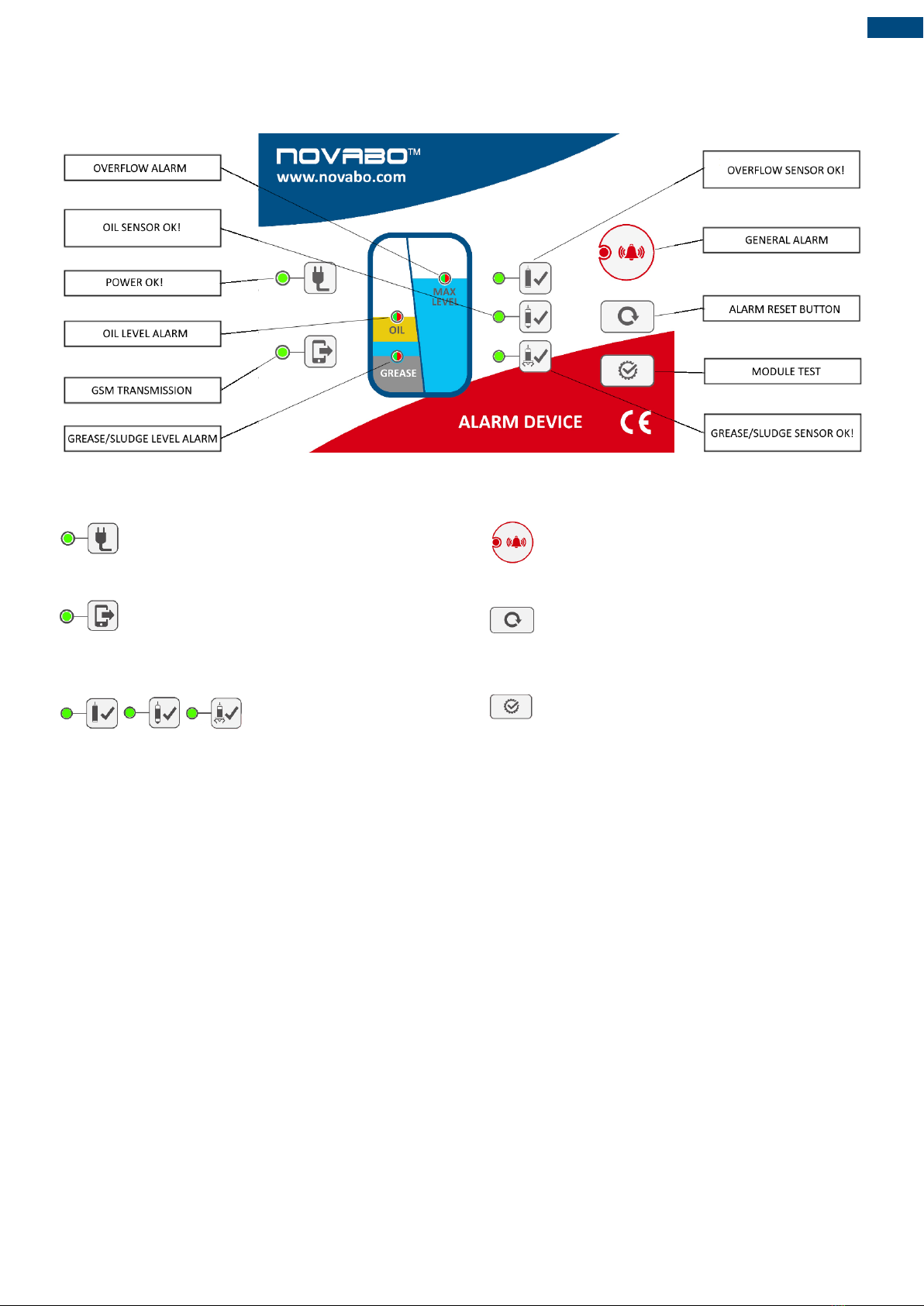
Front panel description
- green LED lights continuously when the power is
ON.
- Blinking LED indicates the correct operation of
the GSM + SIM card. Number of flashes indicates the
strength of the GSM (max 4 flashes).
- LED is ON constantly, when
the sensors are connected and the dipswitches are properly
set. A detailed description of the switch settings is in the
Configuration chapter. Blinking LED indicates an alarm
sensor. Each sensor has a separate red LED.
- The alarm is shown by the steady light of the red
LED + acoustic signal.
- A short press [<1] s button - delete the buzzer alarm.
Long press button [> 2s]- clearing the alarm and restore the
relay to the state without an alarm.
- Checking the optical and acoustic signals and relay
outputs. Test can be activated only when there is no alarm
sensors. Each time you press the button activates /
deactivates the function test.
Technical data
Power supply: R20 3,6V
Power consumption (instantaneous, during GSM
transmission): 7,6VA
Relay outputs REL1 (potential-free contacts)
NO or NC, 0,5A/125VAC or 2A/30VDC
Ambient temperature: -40 to + 60 ° C
Mechanical strength: IK 07
Dimensions of the housing (without glands) (H x W x D): 187 x
122 x 90 mm
Cable glands:
• Probe inputs: 3 x M12, cable dimensions Ø 4.0-6.0 mm
• Power supply: 1xM12 for cable Ø 4.0-6.0 mm
• Sabotage: 1xM12 for cable Ø 4.0-6.0 mm

3
SQUEALER-WRL –manual
Cooperating devices
OILER - thickness
measurement of fat, oil,
mineral oil, organic,
petroleum substances.
SLUDO - detecting the sediment layer
in the separator or the maximum level
COUPLER-01 –hermetic coupling
plug
NFIX-01 –set for mounting the probe
CABLE-5, CABLE-10 –sensor extension
cable
Probes assembly
The sensor mounting should be carried out as follows:
1. Lower the sensor so that the measuring point is at a exceeding
level.
2. Attach the sensor cable to the mounting bracket.
3. Use the COUPLER connector to lengthen the sensor cable
MAX sensor
The probe with a standard length of 5 m should be hung on the FIX holder,
which should be placed directly under the manhole - preferably in the
inspection hole in the separator cover.
OILER sensor
The probe should be placed at the appropriate depth / height and the sensor
cable should be wound around the mounting eye (FIX) in such a way that the
cable is blocked and the probe does not change its position on the handle
during operation.
SLUDO sensor
The mounting height of the sensor depends on the volume of the sludge in the
separator. The amount of accumulated sludge can not exceed 1/3 ÷ 1/2 of the
height between the bottom of the outlet pipe and the bottom of the tank.
When installing the sensor, it should be noted that the deposit usually
accumulates in the measurement zone at different heights, which depends
mainly on the speed of the flowing sewage. Where the flow velocity is the
smallest, it will gather the most and vice versa. Connect the probe with a 5 m
standard cable to the holder. The handles should be placed directly under the
hatch - preferably in the inspection hole in the separator cover.
4
SQUEALER-WRL –manual
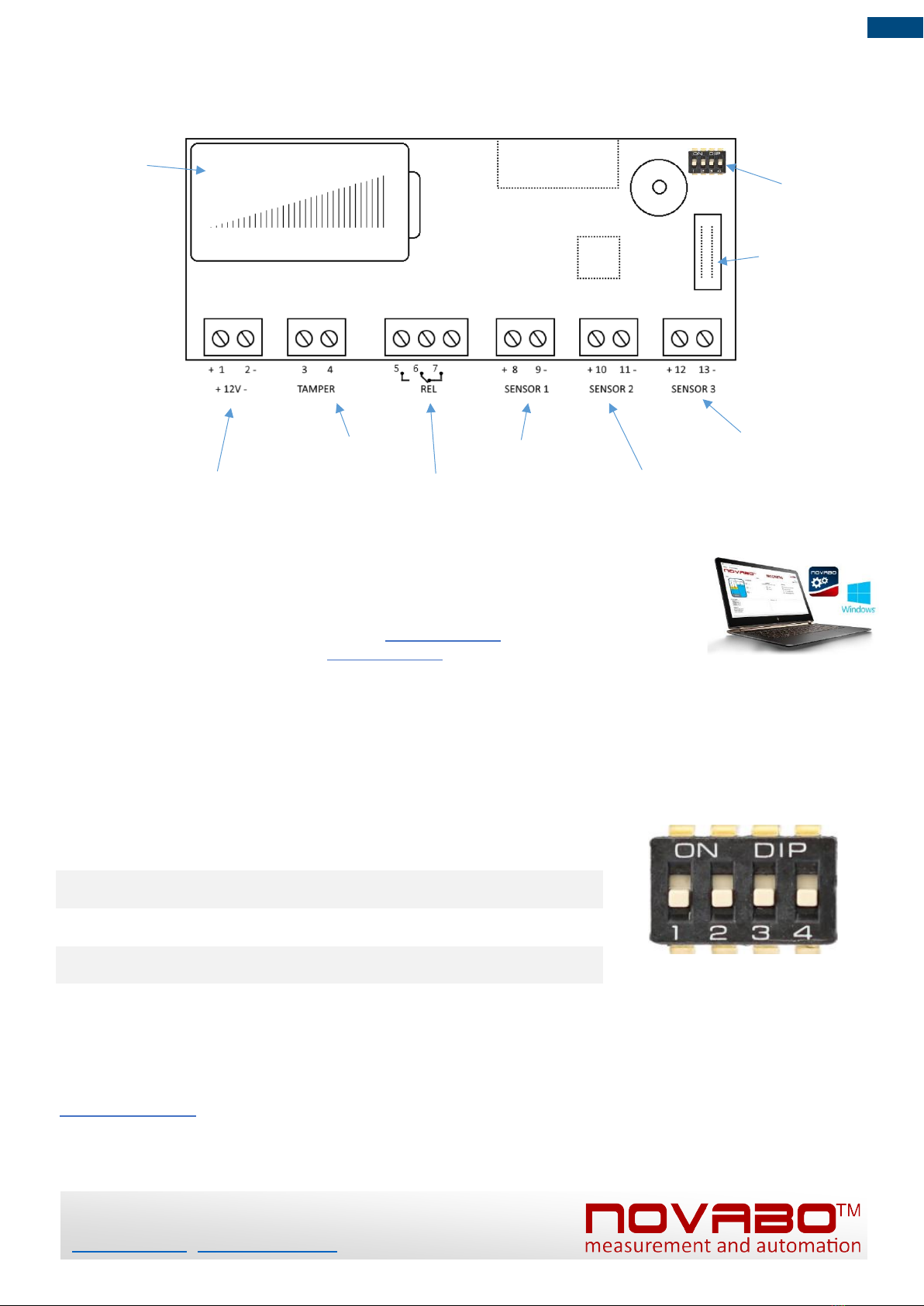
DIP-switches
Battery
Relay output
OILER sensor
MAX sensor
SLUDO sensor
Solar panel
Tamper input
Front panel
connector
Description of controller connectors
PC programming
1. 1. Programming via the Nconfig program, available on the website:
a). install the driver for the USB cable: www.novabo.com >>> products >>> USB driver
b). install NCONFIG software: www.novabo.com >>> products >>> Nconfig
2. In addition, a four-position "DIPSWITCH" type switch is available on the device board inside the housing. It is used to
configure the operation of probes.
DIP SWITCH programming
DIP1
"ON" - sensor MAX active - probe 1 connected
"OFF" - sensor MAX inactive - probe 1 not connected
DIP2
"ON" - sensor OILER active - probe 2 connected
"OFF" - sensor OILER inactive - probe 2 not connected
DIP3
"ON" - sensor SLUDO active - probe 3 connected
"OFF" - sensor SLUDO inactive - probe 3 not connected
DIP4
"ON" - inverse input logic SENSOR 1 (15mA - normal)
"OFF" - normal input logic SENSOR 1 (9mA - normal)
Control and reviews
The manufacturer recommends inspection the entire system every 6 months, or when emptying the separator. For this purpose,
download, print and complete the PeriodicReviewCard.pdf:
www.novabo.com >>> products >>> downloads >>>> PeriodicReviewCard.pdf
During the inspection clean the controller and connected probes, check for mechanical damage. Then perform an electrical and
functional test of the operation of all components of the alarm system.
NOVABO
tel.:+48/58-746-37-73
www.novabo.com , novabo@novabo.com
Popular Security System manuals by other brands


Brooks
Brooks Firetracker FT128 CIE Technical/Programming Manual

Crestron
Crestron PYNG-CONNECT-COM Do guide

Omega Engineering
Omega Engineering CN3271 Series user guide

BRK electronic
BRK electronic First Alert SC9120BA user manual

Chuango
Chuango O2 user manual

Federal Signal Corporation
Federal Signal Corporation PA4000 Installation, operation and service instructions


