NovaFlex Z-Flex DVO User manual

Model DVO
Z-Flex Flexible Insulated Direct Vent System for Oil Burning Appliances
INSTALLATION AND MAINTENANCE INSTRUCTIONS
PRODUCT Flexible Insulated Direct Vent System for oil burning appliances
MANUFACTURER Z-Flex (US) Inc.
20 Commerce Park North
Bedford, New Hampshire 03110-6911 Telephone 603.669.5136
Facsimile 603.669.0309 Toll Free 800.654.5600
COMPONENTS Part # Description
2OILVNT0305 Insulated Flex Vent pipe, 3" inner dia. - 5' long
2OILVNT0310 Insulated Flex Vent pipe, 3" inner dia. - 10' long
2OILVNT0315 Insulated Flex Vent pipe, 3" inner dia. - 15' long
2OILVNT0320 Insulated Flex Vent pipe, 3" inner dia. - 20' long
2OILVNT0405 Insulated Flex Vent pipe, 4" inner dia. - 5' long
2OILVNT0410 Insulated Flex Vent pipe, 4" inner dia. - 10' long
2OILVNT0415 Insulated Flex Vent pipe, 4" inner dia. - 15' long
2OILVNT0420 Insulated Flex Vent pipe, 4" inner dia. - 20' long
2OILCON03 Vent Adaptor, 3" to 3" Flex
2OILCON43 Vent Adaptor, 4" to 3" Flex
2OILCON43IP Vent Adaptor, 4" to 3" Flex /w Inspection Port
2OILCON53IP Vent Adaptor, 5" to 3" Flex /w Inspection Port
2OILCON04 Vent Adaptor, 4" to 4" Flex
2OILCON04IP Vent Adaptor, 4" to 4" Flex /w Inspection Port
2OILCON54IP Vent Adaptor, 5" to 4" Flex /w Inspection Port
2OILCON64IP Vent Adaptor, 6" to 4" Flex /w Inspection Port
2OILCON74IP Vent Adaptor, 7" to 4" Flex /w Inspection Port
2OILTRM404 DVO Termination (Flex -L CFT-4), concentric, 4" exhaust, 4" intake
2OILTRM604 Aerocowl Termination, concentric, 4" exhaust, 4" intake
2OILTRM605 Aerocowl Termination, concentric, 5" exhaust, 4" intake
2OILRISE04 Riser Terminal 36"
1TLXXX0305 3" x 5' Air Intake Flex
1TLXXX0310 3" x 10' Air Intake Flex
1TLXXX0315 3" x 15' Air Intake Flex
1TLXXX0320 3" x 20' Air Intake Flex
1TLXXX0405 4" x 5' Air Intake Flex
1TLXXX0410 4" x 10' Air Intake Flex
1TLXXX0415 4" x 15' Air Intake Flex
1TLXXX0420 4" x 20' Air Intake Flex
4RA43 Adaptor, Reillo BF 3" to 4"
4RA44 Adaptor, Beckett AF 4" to 4"
7HS48XX 3" Clamp
7HS72XX 4" Clamp
4FCVRVX04 4" VRV, Vacuum Relief Valve / Tee
2SILRRTV106X Z-Flex RTV High Temp. Sealant 500F 3oz
2SILRRTV106 Z-Flex RTV High Temp. Sealant 500F 10oz
2SILUC Permatex Ultracopper Sealant 700F 3oz
2SILUC10 Permatex Ultracopper Sealant 700F 8.75oz
APPROVAL AND USE
Consult the appliance manufacturers’ Installation Instructions for approval and guidelines
concerning proper installation. Attention should be paid to the following:
1. Termination a. location b. clearance to combustibles
2. Vent Pipe a. minimum & maximum lengths b. clearance to combustibles c. slope

INSTALLATION NOTES
1. Vent pipe bend radius is 12”
2. Support vent pipe with metal strapping every 36”
3. Maximum wall thickness 14”. Call Z-Flex for recommendations on thicker walls.
4. Kit or system may be based on the specific appliance.
5. System is not designed for common venting. Use for single appliance only.
6. Appliance adaptor test port is for combustion testing required by appliance manufacturer.
7. Follow National Codes for the installation of oil burning appliances. In USA – NFPA 31 In
Canada CAN/CSA B139 and local regulations.
MAINTENANCE
Z-FLEX recommends that the entire heating system, including the appliance and venting
system, be checked annually by a qualified heating professional.
JOINT ASSEMBLY
1. Apply sealant to “threaded” end of vent adaptor.
2. Insert the threaded end in to the vent pipe. Screw the adaptor into the vent pipe in a counter
clockwise direction. The adaptor should be inserted fully until it is tight. If it doesn’t completely
screw into the vent, unscrew and repeat.
3. If the vent needs to be cut to length, use a fine tooth hacksaw. Remove any burrs before
installing adaptor.
2

TERMINATION INSTALLATION
1. Determine location for termination.
2. Cut an 8½” hole through the wall.
3. Pull apart the inner and outer termination sections.
4.Slide the outer wall plate over the outer section of the termination until it rests against the
bead.
5. From the outside the building, insert the outer section through the wall until it rests against
the wall.
6. From the inside, slide the inner wall plate over the outer section and secure it to the wall with
four (4) screws.
7. Position the outer section so that the seam on the flue collar is on the top and the air intake
is on the bottom. Secure to the outer section by tightening the gear clamp around it.
8. Seal with a weather proof sealant around the the bead and edge of the outer wall plate to
avoid water from entering.
TERMINATION CONNECTION
1. Slide the inner section over the vent pipe.
2. Attach the adaptor as per joint assembly.
3. Apply a bead of sealant around the flue collar and slide on adaptor and tighten gear clamp.
4. Seal the seam on the adaptor.
5. Slide the inner section over the outer section and secure by tightening the gear clamp.
6. Stretch the intake flex to the desired length and slide over intake collar and secure by
tightening the gear clamp.
7. Seal the gap between the vent pipe and the inner section with silicone sealant.
3

APPLIANCE CONNECTION
1. Connect the appliance adaptor to the appliance collar as per joint assembly.
2. Apply sealant around the appliance flue collar.
3. Slide the appliance adaptor over the flue collar.
4.Tighten the gear clamp around collar.
5. Install the burner air adaptor. Tighten integral clamp.
6. Put the gear clamp over the intake flex and slide flex over large end of adaptor. Tighten
clamp.
7. A vacuum relief device may be required as per appliance manufacturers’ installation
instructions.
0INSTDVO 3.31.2008
4
The information provided within is for informational purposes only. We have made every effort to ensure the accuracy of the provided information and assume no responsibility for any loss
or damage due to errors or omissions or to the use or misuse of any information supplied. It is impossible to test all products under all conditions to which they might be subjected in the
field. It is therefore the buyer and/or end users’ responsibility to test all products under the conditions that duplicate the service conditions prior to installation. All improvements, all
specifications are subject to change without prior notice. It is the buyer and/or end users’ responsibility to review our complete Terms and Conditions of Sale located on our web sites at:
www.novaflex.com | www.z-flex.com | www.flexmaster.com.
Table of contents
Popular Fan manuals by other brands
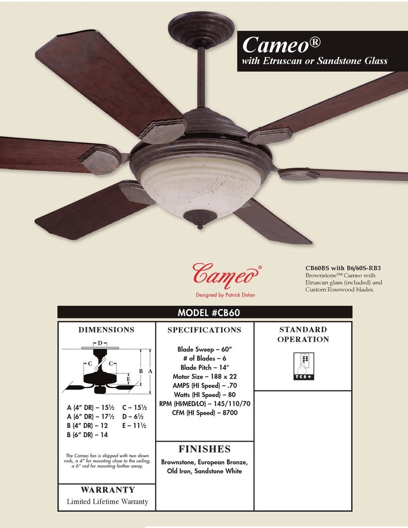
Craftmade
Craftmade Cameo CB60 Specifications
S&P
S&P OZEO E ECOWATT Series installation manual
Omega Altise
Omega Altise OD152W Operation, maintenance and safety instructions

McQuay
McQuay IM-WM1W-0704 installation manual
Martec
Martec DISCOVERY II AC Series installation guide
Brink
Brink Flair 325 2-2 Installation regulations
Alpha Fan
Alpha Fan AX20-5B/56 instruction manual

Hinkley
Hinkley MARIN instruction manual
Alpina
Alpina YH-40R-0 instruction manual

Bionaire
Bionaire BWF0910AR Instruction leaflet
Monte Carlo Fan Company
Monte Carlo Fan Company 5AB52XX Series Owner's guide and installation manual

Commercial Electric
Commercial Electric HVFF16CE Use and care guide
