River of Goods 20187 User manual

MODEL NO.: 20187/20188
1
Installation Guide
MODEL NO.: 20187/20188
You may install your ceiling fan as a flush mount, or you may use the provided down rod(s). Measure your
roomheight before installing the fan and consider the different installation height options indicated in the
above diagram.
Table of Contents:
Safety tips Pg.2-3 Wiring Pg.9-10
Unpacking your fan Pg.4 Canopy Assembly Pg.10
Tools and material required Pg.5 Blade Assembly Pg.10
Outlet Box Pg.6 Light Kit and Shade Assembly Pg.11
Hanging Bracket Installation Pg.5-7 Troubleshooting & Maintenance Pg.12
Fan Assembly (Flush Mount) Pg.8
Fan Assembly (w/Down Rod) Pg.8
Weight of Appliance: 6.9 kg/15.2lb
Model No. 20187/20188
Professional Installation Recommended
Note: Approximate Time of Assembly: 30 Minutes to 1 Hour
PRINTED IN CHINA
READ AND SAVE THESE
INSTRUCTIONS

MODEL NO.: 20187/20188
2
SAFETY TIPS
WARNING: To reduce the risk of electrical shock, turn off the electricity to the fan at the main fuse box or circuit
panel
before you begin the fan installation or before servicing the fan or installing accessories.
1. READ ALL INSTRUCTIONS AND SAFETY INFORMATION CAREFULLY BEFORE INSTALLING YOUR FAN AND SAVE
THESE
INSTRUCTIONS.
CAUTION: To avoid personal injury, the use of gloves may be necessary while handling fan parts with sharp edges.
1.
Make sure all electrical connections comply with Local Codes or Ordinances, the National Electrical Code, and ANSI/NFPA
70-
1999. If you are unfamiliar with electrical wiring or if the house/building wires are different colors than those referred to in the instruction
please use a qualified electrician.
2.
Make sure you have a location selected for your fan that allows clear space for the blades to rotate and at least seven (7) feet
(2.13
meters) of clearance between the floor and the fan blade tips. The fan should be mounted so that the tips of the blades are at
least thirty
(30) inches (76 centimeters) from walls or other upright structures.
3.
The outlet box and ceiling support joist used must be securely mounted, and capable of supporting at least 50 Pounds (23
kilograms). The outlet box must be supported directly by the building structure. Make sure the electrical box that will hold the ceiling fan is
fan-rated. There should be an inscription on the box indicatingit.
WARNING: To reduce the risk of fire, electrical shock, or personal injury, mount to the outlet box marked “Acceptable for Fan Support,”
and use the mounting screws provided with the outlet box. Most outlet boxes commonly used for the support of lighting fixtures are not
acceptable for fan support and may need to be replaced. Consult a qualified electrician if in doubt.
WARNING: To reduce the risk of fire, electrical shock, or personal injury, wire connectors provided with this fan are designed to accept
only one 12 gauge house wire and two lead wires from the fan. If your house wire is larger than 12 gauge or there is more than one house
wire to connect to the two fan lead wires, consult an electrician for the proper size wire connectors touse.
4.
After making electrical connections, spliced conductors should be turned upward and pushed carefully up into the outlet box. The wires
should be spread apart with the grounded conductor and the equipment-grounding conductor on opposite sides of the outlet box.
WARNING: To reduce the risk of electrical shock, fire and to prevent humming noise do not use this fan with any solid state speed control
device or control fan speed with a full range dimmer switch. Using a full range dimmer switch to control fan speed will cause a loud humming
noise fromfan.
5.
Do not operate the reverse switch until fan has come to a completestop.
6.
Do not insert anything between the fan blades while they are rotating.
WARNING: To reduce the risk of personal Injury, do not bend the blade brackets when installing the brackets, balancing the blades,
or
cleaning the fan. Do not insert foreign objects in between rotating fanblades.
WARNING: To avoid personal injury or damage to the fan and other items, be cautious when working around or cleaning
the fan.
7.
Do not use water or detergents when cleaning the fan or fan blades. A dry dust cloth or lightly dampened cloth
will be suitable for most cleaning.
8.
Suitable for use with solid-state speed controls
WARNING: To reduce the risk of personal injury, use only parts provided with this fan. The use of parts OTHER than those provided
with this fan will void thewarranty.
NOTE: The important safety precautions and instructions appearing in the manual are not meant to cover all
possible conditions and situations that may occur. It must be understood that common sense and caution are
necessary factors in the installation and operation of this fan.

MODEL NO.: 20187/20188
3
9.
This appliance is not intended for use by persons (including children) with reduced physical, sensory or mental capabilities, or lack of
experience and knowledge, unless they have been given supervision or instruction concerning use of the appliance by a person responsible
for their safety.
10.
Children should be supervised to ensure that they do not play with the appliance.
11.
CAUTION:MOUNT WITH THE LOWEST MOVING PARTS AT LEAST 2.1 METRES ABOVE FLOOR OR GRADE LEVEL.
12.
WARNING : All set screws must be checked, and retightened where necessary, before installation.
13.
WARNING: If unusual oscillating movement is observed, immediately stop using the ceiling fan and contact the manufacturer, its
service agent or suitably qualified persons.
14.
The replacement of parts of the safety suspension system device and the mounting of the suspension system shall be performed by
the manufacturer, its service agent or suitably qualified persons.
15.
The fixing means for attachment to the ceiling such as hooks or other devices shall be fixed with a sufficient strength to withstand 4
times the weight of the ceiling fan.
MODEL NO.: 20187/20188
4
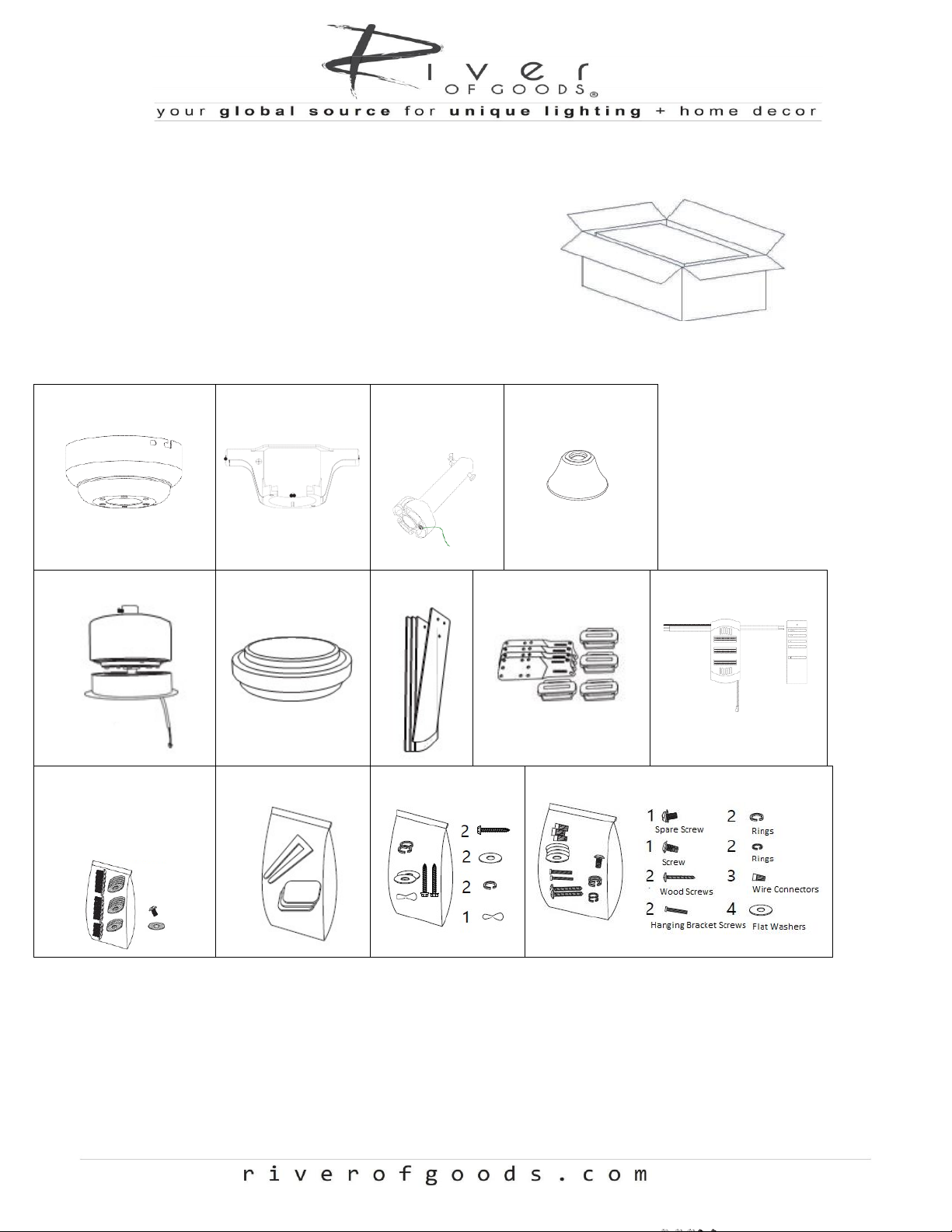
1. Unpacking Your Fan
Carefully open the packaging. Remove items from
styrofoam inserts. Remove motor housing and place on
a soft, dry surface to avoid damage to finish. Donot
discard fan carton or styrofoam inserts should this fan
need to be returned. Check against parts inventory
(listed below) that all parts have beenincluded.
2. Parts Inventory
Canopy
Canopy Bracket
Down rod
5”
Down rod cover
Motor housing
Light Kit & Shade
Blades (4)
Blade Arms
Remote/Receiver
Hardware bag
(13 sets for
Blade
Assembly)
Balancing kit
Security Cable Bag
Hanging Bracket Hardware Bag
MODEL NO.: 20187/20188
5
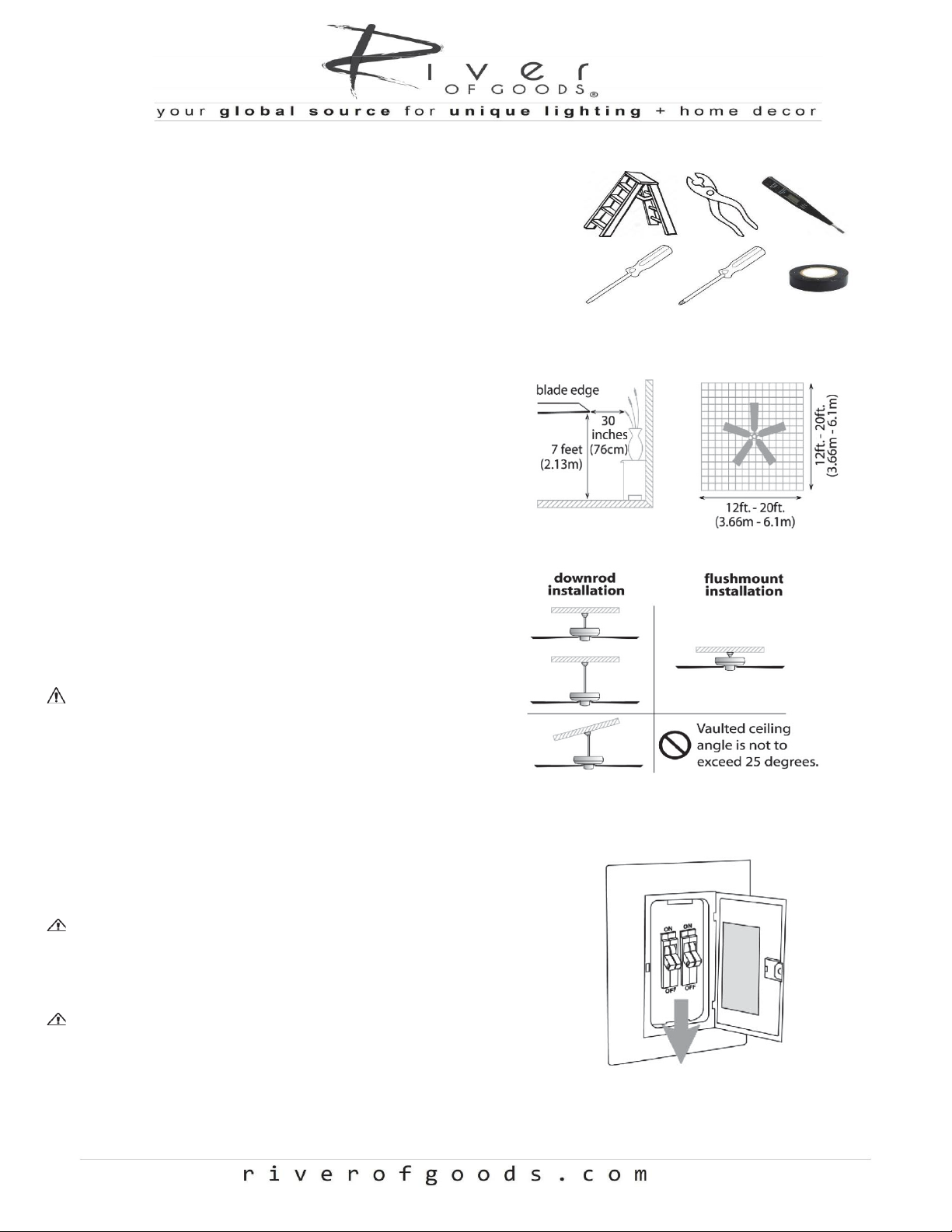
3. Tools Required
•Step ladder
•Pliers
•Screwdriver (flat head and phillips)
•Electrical tape
•Circuit tester
4. Installation Preparation
To prevent personal injury and damage, ensure
that
the hanging location allows the blade a
clearance of 7ft (2.13m) from the floor and 30 in
(76cm) from any wall or obstruction.
The fan is suitable for room sizes up to 400square
feet (37.2 squaremeters).
This fan can be mounted with a down rod
on a normal or vaulted ceiling. Down rod is
included (5” length)
This fan can also be mounted using flushmount
installation as seen indiagram.
WARNING: All set screws must be checked,
and retightened where necessary, before
installation.
5. Hanging Bracket Installation
Turn off circuit breakers to current fixture from breakerpanel
and be sure operating light switch is turned to the OFF
position.
WARNING: Failure to disconnect power supply priorto
installation may result in serious injury and firehazard.
Remove existing fixture
WARNING: When using an existing outlet box, be surethe
outlet box is securely attached to the building structure andcan
support the full weight of the fan. Ensure the outlet box isclearly
marked “Suitable for Fan Support". If not, it must be replaced
with an approved outlet box. Failure to do so can resultin
serious injury.
MODEL NO.: 20187/20188
6
CAUTION: Be sure outlet box is grounded properly and thata
ground wire (green or bare) is present.
Partially loosen screws in slotted holes of canopy.
Remove the other 2 screws (along with the star
washers) -savefor later use. Twist canopy to
remove the hangingbracket.
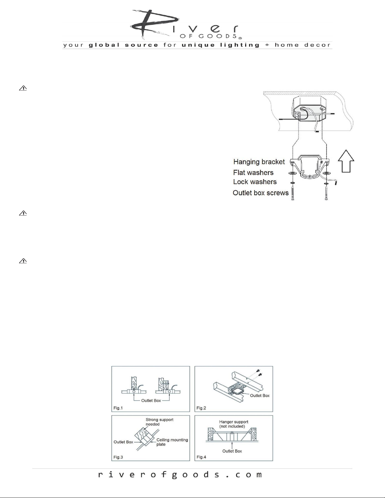
Install hanging bracket to outlet box using original
screws,
spring washers and flat washers provided with
newor original outlet box. If installing on a vaulted
ceiling,face opening of Hanging Bracket towards high
point ofceiling. Arrange electrical wiring around the
back of thehanging bracket and away from the hanging
bracketopening.
CAUTION: It is very important that you use the proper
hardware when installing the hanging bracket as this will
support
the weight of the fan.
ELECTRICAL OUTLET BOX
WARNING: Contact a qualified electrician to replace the outlet box if it is not suitable for ceilingfans
WARNING: To Reduce The Risk Of Fire, Electric Shock, Or Personal Injury, Mount To Outlet Box Acceptable for
Fan Support of 15.9 kg (35 lbs) or less And Use Mounting Screws Provided With The Outlet Box. Most Outlet
Boxes Commonly Used For The Support of Luminaires Are Not Acceptable For Fan Support And May Need To Be
Replaced. Consult A Qualified Electrician If In Doubt. MOUNT ONLY TO AN OUTLET BOX MARKED
ACCEPTABLE FOR FAN SUPPORT。
1. If there is an existing outlet box, ensure it is clearly marked “Suitable For Fan Support”.
If not, it must be replaced with an approvedone.
2.Secure the outlet box (or make sure the existing box is secured) directly tothe building structure. Use appropriate
fasteners and building materials. Woodjoist
and outlet box must be able to support a minimum of 50pounds.
3. Figure 1, 2 and 3 are examples of different ways to mount the outlet boxin different situations.
4. To hang the fan in locations where no ceiling joists is available. A hangersupport
bar may be required (Fig. 4)

MODEL NO.: 20187/20188
7
*Required for Canadian Installation ONLY*
To ensure consumer safety and satisfy Canadian regulatory requirements, a safety support cable is provided to help
prevent the ceiling fan from falling. To install, please follow the instructions below.
Parts
1. Using the provided screw, attach the safety cable hook to the ceiling joist near the mounting bracket. Ensure
the cable hook is covered by the canopy.
2. Adjust the length of the safety cable to reach the safety cable hook by sliding the cable through the nut until
the desired length is reached. Then, form the loop by threading the cable back through the cable and firmly
securing. Place the loop onto the safety cable hook.
Note: Although the safety support cable is only required for Canadian installation, it is recommended that it
is utilized with any installation
MODEL NO.: 20187/20188
8
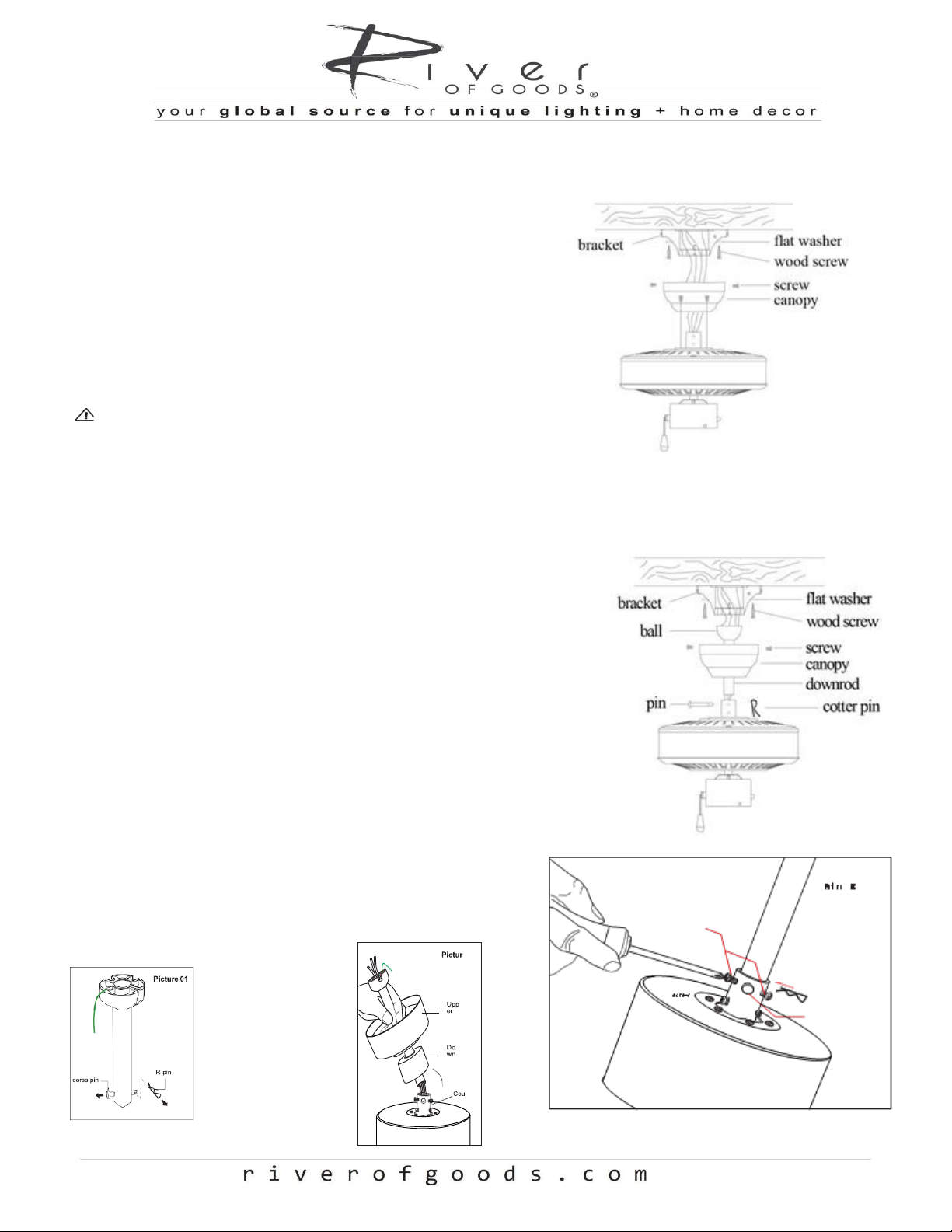
6. Flush Mount Assembly
NOTE: If assembling with down rod, proceed to Step 7
1. Remove ground wire along with the screw and washer
from the mounting plate
2. Remove four (4) screws and spring washers from upper
motor housing
3. Attach canopy to upper motor housing with same screws
and washers removed in Step 2
WARNING –Ensure screws are firmly
secured
4. Hang fan on mounting plate hook through canopy mount
hole for easy hands-free electrical wiring
7. Assembly with Down Rod
1. Remove pin and clip from down rod. Slide the down rod
through the canopy and the down rod cover as shown in
figure
2. Thread the electrical wires through the down rod and pull
the extra wire slack through the down rod
Tip: Apply a small piece of electrical tape to the ends of the
electrical wires to keep them together when threading them
through the down rod
3. Loosen the yoke set screw. Place the down rod into the
motor housing yoke and re-insert the previously removed
pin and clip. Tighten yoke screw securely
4. With the hanging bracket fully secured to the outlet box,
you are now ready to hang your fan. Grab the fan securely
with two (2) hands. Place the down rod ball into the
hanging bracket and rotate until the ball sits securely in
the hanging bracket tab
MODEL NO.: 20187/20188
9
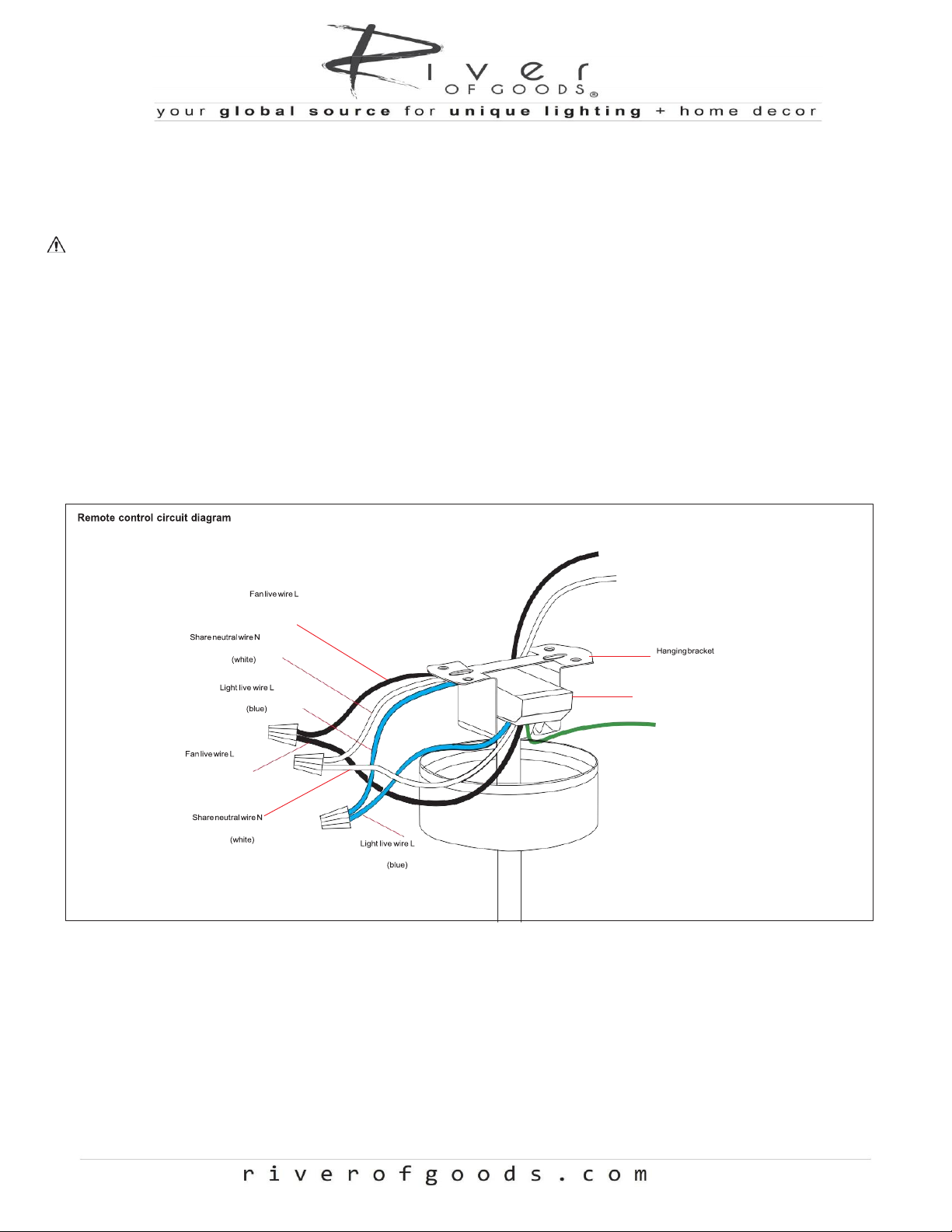
8. Ceiling Fan Wiring and Remote Control
Instructions
WARNING: Failure to disconnect power supply prior to the installation may result in serious injury and fire
hazard
Important: Be sure outlet box is properly grounded or that
a ground wire (GREEN or bare) is present.
Make sure all electrical connections comply with Local
Codes or Ordinances and the National Electrical Code. If you are unfamiliar with electrical wiring, or if the
house/building wires are different colors than those referred to in the instructions, please use a qualified
electrician.
When down rod is secured in place on the hanging bracket, electrical wiring can be made.
Wiring Instructions
Using the diagram above, proceed carefully while making the appropriate wire connections.
The wires should be spread apart with the grounded
conductor and the equipment grounding conductor on
one side of the outlet box and the ungrounded conductor on the other side of the outlet box.
The splices, after being carefully made, should be turned
upward and pushed carefully up into the outlet box.
Power live wire(black)L
Power neutral wire (white) N
(black)
Receiver
Groundwire(Green)E
(black)

MODEL NO.: 20187/20188
10
Note: Wrap each wire nut separately with electrical tape as an
extra safety measure.
Important:
Make sure all electrical connections comply with Local Codes or Ordinances and the National Electrical Code. If
you are unfamiliar with electrical wiring, or if the house/building wires are different colors than those referred to
in the instructions, please use a qualified electrician.
Remote Control Instructions
Note: Your fan is supplied with a radio frequency remote control unit. Kindly note that the fan does not contain a pull
chain/switch for the lighting or fan speed control, as is dependent upon the radio frequency remote for use
In the battery compartment of the remote control, there are two (2) options that can be selected in relation to the
function of the LED light kit (shown below for reference)
1) D –LED light kit is dimmable
2) CFL –LED light is *not* dimmable and only operates as On/Off
9. Canopy Assembly
1. Loosen the four (4) screws/washers on the side of the
hanging bracket
2. Lift canopy to the hanging bracket, and secure the
canopy with the four (4) screws/washers. Securely tighten
screws
10. Blade Assembly
Insert blade through slide slot of motor and align with
1. three (3) holes
2. Secure the blades with three (3) blade screws. Be
careful not to overtighten.
3. Repeat Step 3 for the remaining blades
MODEL NO.: 20187/20188
11
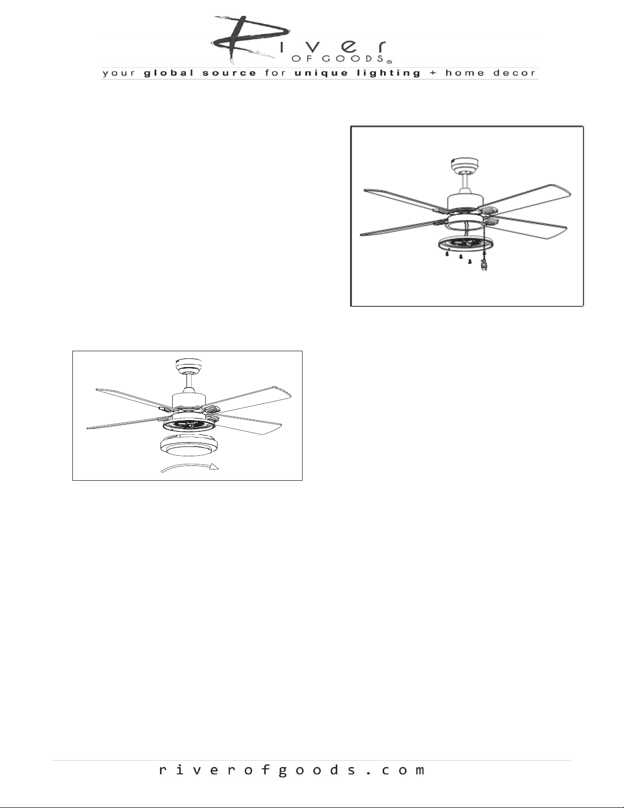
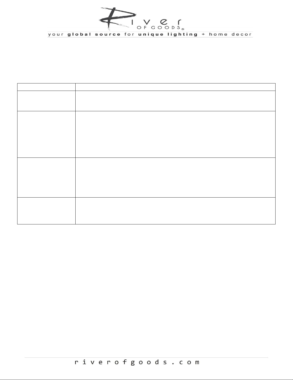
11. Light Kit Assembly
1. Remove the four (4) screws from the light kit and set
aside
2. Plug the connector from the light kit into the connectors
from the switch housing
3. Correct wiring
oWhite to White
oBlue to Blue
4. Gently push the connectors into the switch housing and
align the holes in the light kit with the holes in the switch
housing. Secure the light kit with the four (4) removed
screws
5. Alight the light kit cover and tighten
MODEL NO.: 20187/20188
12
Ceiling Fan Troubleshooting Guide
Welcome to the River of Goods family! We’re honored you’ve decided to include one of our ceiling fans in your home.
Problem
Solution
Fan/Lights do not start
•Check all fuses/circuit breakers
•Turn off electrical power and ensure the wiring is correct
•Ensure light kit wires are securely connected
Fan is noisy
•Allow a 24-hour “break in” period. Any level of noise louder than ambient levels
should disappear during that time
•Check the electrical mounting box and ensure it is securely fastened
•Check all screws/wire connections on the fan to ensure they are securely fastened
•Use of an unapproved light dimmer or wall control can cause harmonic distortion
and excess noise. Check to ensure that if installed, the wall control is approved for
ceiling fan use
Fan does not move
much air
•Check the direction of the fan blades when running. If needed, flip the reverse
switch on the motor housing to ensure the ceiling fan is moving air in the desired
direction
•Ensure no household items are obstructing the airflow of the ceiling fan
•Check to ensure the ceiling fan is appropriate for the size of the room in which it is
installed
Fan shakes or wobbles
•A small amount of wobble is typical and acceptable and is not indicative of a defect
•Ensure the electrical mounting box and hanging bracket are securely fastened
•Install the included balancing kit. If undesired movement persists, simply change
the location of the balancing kit until the excess movement ceases
MAINTENANCE
1.
The fan natural movements may cause some connections to work loose. A clicking or rattling noise is a
certain sign of loosening screws. Check the support connections, brackets and blade attachment twice
a year, and tighten all screws as necessary.
2.
Clean your fan periodically. Use only a damp cloth (never use solvents), and dust with a soft cloth or
brush.
3.
Youwill never need to oil your fan, its permanently sealed bearing will preventnoise.
4.
Make sure the power is turned off at the main fuse or circuit panel before you attempt any repairs.
This manual suits for next models
1
Table of contents
Other River of Goods Fan manuals


Popular Fan manuals by other brands


Broan
Broan NuTone RDFU installation guide

LUCCI Air
LUCCI Air OSPREY 216170 Installation operation & maintenance

Chore-Time
Chore-Time TURBO installation manual

Boneco
Boneco F120 manual

Trox Technik
Trox Technik TFM Installation and maintenance manual

Lasko
Lasko T48311 Important instructions & operating manual