Novanta ATI Axia80 User manual


Manual, F/T Sensor, Ethernet Axia
Document #9620-05-C-Ethernet Axia-02
Pinnacle Park • 1031 Goodworth Drive •Apex, NC 27539 • Tel:+1 919.772.0115 • Fax:+1 919.772.8259 • www.ati-ia.com
C-2
Foreword
Information contained in this document is the property of ATI IndustrialAutomation, Inc. and shall not be reproduced in
whole or in part without prior written approval of ATI IndustrialAutomation, Inc. The information herein is subject to
change without notice and should not be construed as a commitment on the part of ATI IndustrialAutomation, Inc. This
manual is periodically revised to reect and incorporate changes made to the F/T system.
ATI IndustrialAutomation, Inc. assumes no responsibility for any errors or omissions in this document.
Copyright© (2022) by ATI IndustrialAutomation, Inc., Apex, North Carolina USA. All Rights Reserved.
Published in the USA.
ATI F/T Sensing Systems are considered components/ semi-nished goods intended for use in larger system/
device/ nished good.
In consideration that ATI Industrial Automation, Inc. (ATI) products are intended for use with robotic and/or automated
machines, ATI does not recommend the use of its products for applications wherein failure or malfunction of aATI
component or system threatens life or makes injury probable. Anyone who uses or incorporates ATI components within
any potentially life threatening system must obtain ATI’s prior consent based upon assurance to ATI that a malfunction
of ATI’s component does not pose direct or indirect threat of injury or death, and (even if such consent is given) shall
indemnify ATI from any claim, loss, liability, and related expenses arising from any injury or death resulting from use of
ATI components.
All trademarks belong to their respective owners. Windows®is a registered trademark of Microsoft Corporation.
Note:
Please read the manual before calling customer service, and have the following
information available:
1. Serial number (e.g., FT01234)
2. Sensor model (e.g., Axia90-M50)
3. Calibration (e.g., US-15-50, SI-65-6, etc.)
4. Accurate and complete description of the question or problem
• For the status code bit map; refer to Section 5.5—Status Code.
• For checking the system’s status, issue a “Status” command (refer to Table 8.1) or
view the System Information webpage (refer to Section 6.8—System Information
Page (manuf.htm)).
5. Computer and software information (operating system, PC type, drivers, application
software, and other relevant information about the application’s conguration)
Be near the F/T system when calling (if possible).
Please contact an ATI representative for assistance, if needed:
Sale, Service and Information about ATI products:
ATI Industrial Automation
1031 Goodworth Drive
Apex, NC 27539 USA
www.ati-ia.com
Tel: +1.919.772.0115
Fax: +1.919.772.8259
Application Engineering
Tel: +1.919.772.0115, Extension 511
Fax: +1.919.772.8259
E-mail: [email protected]
24/7 Support: +1 855 ATI-IA 00 (+1 855-284-4200)

Manual, F/T Sensor, Ethernet Axia
Document #9620-05-C-Ethernet Axia-02
Pinnacle Park • 1031 Goodworth Drive •Apex, NC 27539 • Tel:+1 919.772.0115 • Fax:+1 919.772.8259 • www.ati-ia.com
C-3
Table of Contents
Glossary........................................................................................................................................C-7
1. Safety....................................................................................................................................C-10
1.1 ExplanationofNotications................................................................................................... C-10
1.2 General Safety Guidelines...................................................................................................... C-10
1.3 Safety Precautions...................................................................................................................C-11
2. Product Overview................................................................................................................C-12
3. Installation ...........................................................................................................................C-13
3.1 Installation of the Sensor to the Robot................................................................................. C-13
3.2 CableConguration ................................................................................................................ C-14
3.3 PinandWireAssignmentsforConnectors .......................................................................... C-14
3.3.1 Pin Assignment for theAxia F/T Sensor....................................................................... C-15
3.3.1.1 Axia80 6-Pin M8 Male Connector................................................................. C-15
3.3.1.2 Axia80 and Axia90 8-pin M8 Male Connector............................................... C-15
3.3.1.3 Axia130 8-pin M12 Male Connector ............................................................. C-15
3.3.2 Axia80 Sensor Cable (P/N 9105-C-ZC22-ZC28-X)...................................................... C-16
3.3.3 Axia80 and Axia90 Sensor Cable (P/N 9105-C-ZC27-ZC28-X)................................... C-16
3.3.4 Axia130 Sensor Cable (P/N 9105-C-ZC28-ZC28-X).................................................... C-17
3.3.5 Ethernet Cable (P/N 9105-C-ZC28-U-RJ45S-X).......................................................... C-18
4. ConnectingThroughEthernet ...........................................................................................C-19
4.1 IPAddressCongurationforEthernet.................................................................................. C-19
4.2 ConnectingTotheATIWebpagesUsingaWindowsComputer ......................................... C-20
4.3 FindingtheEthernetAxiaSensoronaNetwork .................................................................. C-23
5. Operation .............................................................................................................................C-25
5.1 LED Self-Test Sequence ......................................................................................................... C-25
5.2 LED Normal Operation............................................................................................................ C-26
5.2.1 Sensor Status LED....................................................................................................... C-26
5.2.2 Diag LED...................................................................................................................... C-26
5.2.3 Ethernet Link/Activity LED............................................................................................ C-26
5.3 Sample Rate............................................................................................................................. C-27
5.3.1 Sample Rate Versus Data Rate ................................................................................... C-27
5.4 Low-Pass Filter........................................................................................................................ C-27
5.5 Status Code ............................................................................................................................. C-31
5.5.1 Status Code: Sensing Range Exceeded...................................................................... C-32
6. ATIEthernetAxiaWebpagesInterface..............................................................................C-34
6.1 WelcomePage(index.htm)..................................................................................................... C-34
6.2 SnapshotPage(rundata.htm) ................................................................................................ C-35

Manual, F/T Sensor, Ethernet Axia
Document #9620-05-C-Ethernet Axia-02
Pinnacle Park • 1031 Goodworth Drive •Apex, NC 27539 • Tel:+1 919.772.0115 • Fax:+1 919.772.8259 • www.ati-ia.com
C-4
6.3 DemoPage(demo.htm) .......................................................................................................... C-36
6.4 ADCSettingsPage(setting.htm) ........................................................................................... C-36
6.5 ThresholdingPage(moncon.htm) ......................................................................................... C-37
6.6 F/T CongurationsPage(cong.htm) ................................................................................... C-41
6.7 CommunicationPage(comm.htm) ........................................................................................ C-42
6.8 SystemInformationPage(manuf.htm) ................................................................................. C-44
6.9 StatusLogPage(status.htm)................................................................................................. C-45
6.10 InterfaceExamplePage(examples.htm)............................................................................... C-46
6.11 ATI Website Menu Item ........................................................................................................... C-47
7. Java®Demo Application .....................................................................................................C-48
7.1 StartingtheDemo ................................................................................................................... C-48
7.2 Data Display with the Demo................................................................................................... C-50
7.3 CollectingDatawiththeDemo............................................................................................... C-50
7.4 Demo CSV File Format............................................................................................................ C-52
7.5 The Errors Field Display of the Demo................................................................................... C-54
7.6 DevelopingaCustomizedJava®Application........................................................................ C-54
8. ConsoleInterfaceThroughTelnet .....................................................................................C-55
8.1 SettingUpaConsoleInterfaceThroughTelnet ................................................................... C-55
8.2 Console Commands................................................................................................................ C-56
8.3 Console “CAL” | “SET” Command Fields and Values......................................................... C-58
8.4 Query Commands: “S” or “C” ............................................................................................... C-63
8.4.1 Converting Counts Per Force/Torque to FT Values...................................................... C-64
8.4.2 Secondary Commands for the Query “C” or “S” Command......................................... C-64
8.4.3 ExamplesofSecondaryCommands(Speciers)......................................................... C-65
8.4.4 HowtoInterprettheOutputfrom“!”Specier .............................................................. C-67
8.5 ExampleofToolTransformationFunctionalityThroughTelnet ......................................... C-68
9. CommonGatewayInterface(CGI) .....................................................................................C-70
9.1 URLSyntaxConstruction:.................................................................................................................. C-70
9.1.1 Assigning New Values to a Variable............................................................................. C-70
9.2 CGIVariable:Settings(setting.cgi) ....................................................................................... C-71
9.3 ThresholdingCGI(moncon.cgi)............................................................................................. C-71
9.4 CGIVariable:Congurations(cong.cgi) ............................................................................. C-72
9.4.1 Example of Tool Transformation Functionality Through CGI........................................ C-73
9.5 CGIVariable:Communications(comm.cgi).......................................................................... C-74
10. TCP Interface .......................................................................................................................C-75
10.1 Command Codes..................................................................................................................... C-75

Manual, F/T Sensor, Ethernet Axia
Document #9620-05-C-Ethernet Axia-02
Pinnacle Park • 1031 Goodworth Drive •Apex, NC 27539 • Tel:+1 919.772.0115 • Fax:+1 919.772.8259 • www.ati-ia.com
C-5
10.2 Read F/T Command................................................................................................................. C-75
10.3 Read F/T Response................................................................................................................. C-75
10.4 Read Calibration Info Command............................................................................................ C-76
10.5 Read Calibration Info Response............................................................................................ C-76
10.6 Write Tool Transform Command............................................................................................ C-77
10.7 Write Monitor Condition Command....................................................................................... C-77
10.8 Write Response ....................................................................................................................... C-77
11. XML Interface.......................................................................................................................C-78
11.1 SystemandCongurationInformation(netftapi2.xml) ....................................................... C-78
11.2 CalibrationInformation(netftcalapi.xml) .............................................................................. C-80
12. UDPInterfaceUsingRDT....................................................................................................C-81
12.1 RDT Protocol ........................................................................................................................... C-81
12.1.1 RDT Request For Records Structure ........................................................................... C-82
12.1.2 RDT Records Sent Structure........................................................................................ C-82
12.2 CalculatingF/TValuesforRDT .............................................................................................. C-83
12.3 Multiple Clients........................................................................................................................ C-83
12.4 NotesonUDPandRDTMode ................................................................................................ C-83
12.5 Example Code.......................................................................................................................... C-83
13. Troubleshoot........................................................................................................................C-84
13.1 LED Errors ............................................................................................................................... C-84
13.2 Ethernet Communication Questions and Errors.................................................................. C-85
13.3 EthernetAxiaWebpageErrors............................................................................................... C-86
13.4 Java®Demo Errors.................................................................................................................. C-86
13.5 BasicGuidanceforTroubleshooting .................................................................................... C-87
13.6 ReducingNoise ....................................................................................................................... C-92
13.6.1 Mechanical Vibration.................................................................................................... C-92
13.6.2 Electrical Interference................................................................................................... C-92
13.7 ImprovingEthernetThroughput ............................................................................................ C-92
13.7.1 Direct Connection between Axia Ethernet and Host .................................................... C-92
13.7.2 Choice of Operating System ........................................................................................ C-92
13.7.3 Increasing Operating System Performance ................................................................. C-92
13.7.4 Avoid Logging the Host to a Company Network........................................................... C-93
13.7.5 Use a Dedicated Network............................................................................................. C-93

Manual, F/T Sensor, Ethernet Axia
Document #9620-05-C-Ethernet Axia-02
Pinnacle Park • 1031 Goodworth Drive •Apex, NC 27539 • Tel:+1 919.772.0115 • Fax:+1 919.772.8259 • www.ati-ia.com
C-6
14. Specications ......................................................................................................................C-93
14.1 ElectricalSpecications ......................................................................................................... C-93
14.2 CableSpecications ............................................................................................................... C-93
14.2.1 P/N 9105-C-ZC22-ZC28-X........................................................................................... C-93
14.2.2 P/N 9105-C-ZC27-ZC28-X........................................................................................... C-93
14.2.3 P/N 9105-C-ZC28-ZC28-X........................................................................................... C-94
14.2.4 P/N 9105-C-ZC28-U-RJ45S-X ..................................................................................... C-94
15. Terms and Conditions of Sale............................................................................................C-95

Manual, F/T Sensor, Ethernet Axia
Document #9620-05-C-Ethernet Axia-02
Pinnacle Park • 1031 Goodworth Drive •Apex, NC 27539 • Tel:+1 919.772.0115 • Fax:+1 919.772.8259 • www.ati-ia.com
C-7
Glossary
Term Denitions
ActiveConguration Thecongurationthatthesystemiscurrentlyusing.
ADC Analog-to-digital converter
Bias
Biasingisusefulforeliminatingtheeectsofgravity(toolweight)orotheracting
forces. When the bias function is used, the software collects data for the forces and
torques that are currently acting on the sensor and use these readings as a reference
for future readings. Future readings will have this reference subtracted from them
before they are transmitted. Bias may also be referred to as “zero out” or “tare”
the sensor.
Calibration Denesaspecicmeasurementorsensingrangeforagivensensor.Calibrationis
also the act of measuring a transducer’s raw response to loads and creating data
used in converting the response to forces and torques.
CGI Common Gateway Interface (CGI) is the method of using web URLs to communicate
data and parameters back to a web device.
Complex Loading Any force or torque load that is not purely in one axis.
Conguration User-denedsettingsthatincludewhichforceandtorqueunitsarereportedand
which calibration is to be used.
Control Panel A feature on a personal computer operating system where a user can adjust
system settings.
Coordinate Frame See Sensor Reference Frame Origin.
Data Rate How fast data can be output over the network.
DHCP DynamicHostCongurationProtocol(DHCP)isanautomaticmethodforEthernet
equipment to obtain an IP address. The EthernetAxia system can obtain its IP
address using DHCP on networks that support this protocol.
DINT Signed double integer (32 bit)
ENABL Boolean that uses Enabled to represent 1 and Disabled to represent 0
Ethernet A family of computer networking technologies commonly used in local area networks.
Fieldbus A generic term referring to any one of a number of industrial computer networking
standards. Examples include: Ethernet, CAN, Modbus, and PROFINET.
FT or F/T Force and Torque.
Fxy The resultant force vector comprised of components Fxand Fy.
Force A force is a push or pull action on an object caused by an interaction with another
object. Force = mass X acceleration
HEXnHexadecimal number of nbits,prexedwith0x
HTTP GET Method Astandardandcommonmethodthatausercanrequestdatafromaspecied
resource such as a sensor. HTTP works as a request-response protocol between
client (web browser) and server (the sensor).
Hysteresis Asourceofmeasurementerrorcausedbytheresidualeectsof
previously applied loads.
INT Signed integer (16 bit)
Interface Plate
A separate plate that attaches the sensor to another surface. Interface plates are
often used if the bolt pattern on the sensor doesn’t match the bolt pattern on the
robot arm or customer tooling. The interface plate has two bolt patterns, one on either
side of the plate. One side is for the sensor. The other side is for the robot arm or
customer tooling.
IP64 Ingress protection rating “64” designates protection against dust and splashing of
water. An IP64 rating does not guarantee protection when a user submerges a device
inwateroranytypeofuid.
IP67 Ingress protection rating “67” designates protection against dust and submersion
under 1 m of fresh water.

Manual, F/T Sensor, Ethernet Axia
Document #9620-05-C-Ethernet Axia-02
Pinnacle Park • 1031 Goodworth Drive •Apex, NC 27539 • Tel:+1 919.772.0115 • Fax:+1 919.772.8259 • www.ati-ia.com
C-8
Term Denitions
IPAddress An IP Address (Internet Protocol Address) is an electronic address assigned to an
Ethernet device so that it may send and receive Ethernet data. IP addresses may be
either manually selected by a user or automatically assigned by the DHCP protocol.
Java™ Java is a programming language often used for programs on webpages. The
Ethernet Axia demo is a Java application. Java is a registered trademark of Sun
Microsystems, Inc.
MAC Media Access Controller is the hardware that implements the lowest sub-layer of the
data link layer.
MAC Address MAC Addresses (Media Access Control Addresses) are the unique addresses
given to every Ethernet device when it is manufactured, to be used as an electronic
Ethernet serial number.
MAC ID MediaAccessCodeIdentier(MACID)isauniquenumberthatisuserassignedto
each device on an Ethernet network. Also called Node Address.
Measurement Uncertainty
Commonly referred to as “accuracy”, “measurement uncertainty” is the worst-
case error between the measured value and the true load. The measurement
uncertaintyisspeciedasapercentageofthefull-scalemeasurementrangefor
a given sensor model and calibration size. This value takes into account multiple
sourcesoferror.Thesensor’scalibrationcerticateliststhemeasurement
uncertainty percentage. For more information, refer to Section 2.2: Measurement
Uncertainty in the Frequently Asked Questions (FAQ) document located at:
https://www.ati-ia.com/library/documents/FT_FAQ.pdf.
Mechanical Coupling When an external object such as customer tooling or utilities contacts a sensor’s
surface between the sensor’s mounting side and tool side.
N/A Not Applicable
NVM Non-Volatile Memory. Storage of information or device memory that can be retrieved
even after the device goes through a power cycle.
Overload The condition where more load is applied to the sensor than the rated measurement
range that can be applied to the sensor. Overloads result in reduced accuracy and
potentially reduced sensor life.
Plug-in Technology A customized program that when downloaded and installed onto a host device adds
aspecicfeaturetoanexistingcomputerprogram.
P/N Part Number
Power Cycle When a user removes and then restores power to a device.
REAL Floating-point number (32 bit)
RDT The rate per second at which the sensor sends streaming RDT data to a
host. Raw Data Transfer (RDT) is a fast and simple Ethernet protocol for control and
data transfer via UDP.
RDTBuerSize
A mode where the sensor sends more than one data package per sample. Multiple
datapackagesarebueredandsentinoneblock.Bueringreducestheamountof
overheaddatasentfromthesensorandreducestheoverallnetworktrac.
Sensor Reference Frame Origin The point on the sensor from which all forces and torques are measured.
Sensor System (or
conguration)
The entire assembly consisting of a sensor body and a system interface to translate
forceandtorquesignalsintoaspeciccommunicationinterface/protocol.
Resolution The smallest change in load that can be measured.
Sample Rate How fast the ADCs are sampling inside the unit.
Sensor The component that converts a detected load into electrical signals.
SINT Signed short integer (8 bit)
STRINGnString of ncharacters
Status Bit A unit of computer data sent from the ATI F/T sensor.

Manual, F/T Sensor, Ethernet Axia
Document #9620-05-C-Ethernet Axia-02
Pinnacle Park • 1031 Goodworth Drive •Apex, NC 27539 • Tel:+1 919.772.0115 • Fax:+1 919.772.8259 • www.ati-ia.com
C-9
Term Denitions
TCP Transmission Control Protocol (TCP) is a low-level method of transmitting data over
Ethernet. TCP provides a slower, more reliable delivery of data than UDP.
Thresholding A software function of the sensor that performs a simple arithmetic comparison of a
user-denedthresholdtotheloadingonatransduceraxis.
Torque The application of a force through a lever or moment arm that causes something to
want to turn. For example, a user applies torque to a screw to make it turn.
Torque = force x moment arm length
Txy The resultant torque vector comprised of components Txand Ty.
UART Universal asynchronous receiver transmitter.
UDINT Unsigned double integer (32 bit)
UDP UDP (User Datagram Protocol) is a low-level method of transmitting data over
Ethernet. While UDP is faster than TCP, unlike TCP lost UDP data is not resent.
UINT Unsigned integer (16 bit)
USINT Unsigned short integer (8 bit)
Manual, F/T Sensor, Ethernet Axia
Document #9620-05-C-Ethernet Axia-02
Pinnacle Park • 1031 Goodworth Drive •Apex, NC 27539 • Tel:+1 919.772.0115 • Fax:+1 919.772.8259 • www.ati-ia.com
C-10
1. Safety
The safety section describes general safety guidelines to be followed with this product, explanations of the
notications found in this manual, and safety precautions that apply to the product. Product specic notications
are imbedded within the sections of this manual (where they apply).
1.1 ExplanationofNotications
These notications are used in all of ATI manuals and are not specic to this product. The user should heed
all notications from the robot manufacturer and/or the manufacturers of other components used in the
installation.
DANGER: Noticationofinformationorinstructionsthatifnotfollowedwillresultin
deathorseriousinjury.Thenoticationprovidesinformationaboutthenatureofthe
hazardous situation, the consequences of not avoiding the hazard, and the method for
avoiding the situation.
WARNING: Noticationofinformationorinstructionsthatifnotfollowedcouldresult
indeathorseriousinjury.Thenoticationprovidesinformationaboutthenatureofthe
hazardous situation, the consequences of not avoiding the hazard, and the method for
avoiding the situation.
CAUTION:Noticationofinformationorinstructionsthatifnotfollowedcouldresult
inmoderateinjuryorwillcausedamagetoequipment.Thenoticationprovides
information about the nature of the hazardous situation, the consequences of not
avoiding the hazard, and the method for avoiding the situation.
NOTICE: Noticationofspecicinformationorinstructionsaboutmaintaining,operating,
installing, or setting up the product that if not followed could result in damage to equipment. The
noticationcanemphasize,butisnotlimitedto:specicgreasetypes,bestoperatingpractices,
and maintenance tips.
1.2 General Safety Guidelines
The customer should verify that the sensor is rated for the maximum load and torque expected during
operation. Because static forces are less than the dynamic forces from the acceleration or declaration of the
robot, be aware of the dynamic loads caused by the robot.
Manual, F/T Sensor, Ethernet Axia
Document #9620-05-C-Ethernet Axia-02
Pinnacle Park • 1031 Goodworth Drive •Apex, NC 27539 • Tel:+1 919.772.0115 • Fax:+1 919.772.8259 • www.ati-ia.com
C-11
1.3 Safety Precautions
CAUTION:Modifying or disassembly of the sensor could cause damage and void
the warranty. Use the supplied mounting interface plate and the provided tool side
mounting bolt pattern to mount the sensor to the robot and customer tooling to the
sensor. For more information, refer to the ATI customer drawings.
CAUTION:Probing openings in the sensor causes damage to the instrumentation.
Avoid prying into the openings of the sensor.
CAUTION:Do not overload the sensor. Exceeding the single-axis overload values of
the sensor causes irreparable damage.
CAUTION:The sensor should be protected from impact and shock loads that
exceed rated ranges during transportation as the impacts can damage the sensor’s
performance. For more information about rated ranges, refer to the appropriate sensor
manual in Table 2.1.
Manual, F/T Sensor, Ethernet Axia
Document #9620-05-C-Ethernet Axia-02
Pinnacle Park • 1031 Goodworth Drive •Apex, NC 27539 • Tel:+1 919.772.0115 • Fax:+1 919.772.8259 • www.ati-ia.com
C-12
2. Product Overview
The Ethernet Axia Force/Torque (F/T) sensor measures six components of force and torque (Fx \ Fy \ Fz\ Tx\ Ty
\ Tz) and communicates this data to a device (such as a personal computer, robot, or PLC) that is compatible with
an Ethernet communication interface. The ATI Axia-series product line differs from the other (non-Axia) ATI F/T
sensor models. Thus, the Axia sensors have different options and available features. The Axia-series force/torque
sensors are available in several different payload and communication interface versions. This manual covers the
following topics for the Ethernet Axia interface version:
• Electrical specications and wire information for cables
• Initial set-up of a serial console for Ethernet communications
• Operation (LEDs, lter rates, sampling rates, and Status codes)
• Compatibility with the ATI Net F/T sensor UDP interface and Java demo application (for more
information, refer to Section 12—UDP Interface Using RDT, Section 7—Java® Demo Application, and
the 9620-05-NET F/T manual)
• Compatibility with parts of the ATI Net F/T web interface (for more information, Section 6—ATI
Ethernet Axia Webpages Interface and the 9620-05-NET F/T manual)
• ATI Ethernet Axia F/T sensor conguration through software interfaces: console interface through
Telnet, Common Gateway Interface (CGI), TCP interface, UDP (RDT) interface, and XML
• Troubleshooting guidance that relates to Ethernet Axia
For additional sensor information, such as installation on a robot, operation, and general troubleshooting, refer to
the appropriate ATI Axia F/T sensor manual listed in the following table:
Table 2.1—ATI Axia F/T Sensor Manual
ATI Axia Sensor Model RefertotheATIAxiaF/TSensorManualDocumentNumber(#):
Axia80 ATI F/T Axia80 Sensor Manual
(ATI Document #9620-05-B-Axia80)
Axia90 ATI F/T Axia90 Sensor Manual
(ATI Document #9620-05-B-Axia90)
Axia130 ATI F/T Axia130 Sensor Manual
(ATI Document #9620-05-B-Axia130)
Manual, F/T Sensor, Ethernet Axia
Document #9620-05-C-Ethernet Axia-02
Pinnacle Park • 1031 Goodworth Drive •Apex, NC 27539 • Tel:+1 919.772.0115 • Fax:+1 919.772.8259 • www.ati-ia.com
C-13
3. Installation
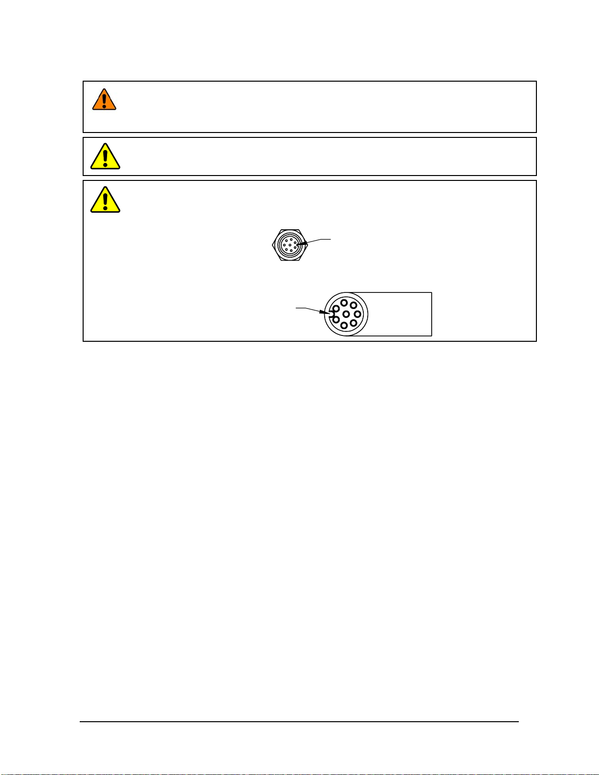
WARNING: Performing maintenance or repair on the sensor when circuits (for example:
power, water, and air) are energized could result in death or serious injury. Discharge and
verify all energized circuits are de-energized in accordance with the customer’s safety
practices and policies.
CAUTION:Avoid damage to the sensor from electrostatic discharge. Ensure proper
grounding procedures are followed when handling the sensor or cables connected to the
sensor. Failure to follow proper grounding procedures could damage the sensor.
CAUTION:Do not apply excessive force to the sensor and cable connector during
installation, or damage will occur to the connectors. Align the keyway on the sensor and cable
connector during installation to avoid applying excessive force to the connectors.
Keyway on the
cable connector.
Keyway on the
sensor connector.
3.1 Installation of the Sensor to the Robot
For instructions on how to install the sensor to the robot, refer to the appropriate sensor manual in Table 2.1.

Manual, F/T Sensor, Ethernet Axia
Document #9620-05-C-Ethernet Axia-02
Pinnacle Park • 1031 Goodworth Drive •Apex, NC 27539 • Tel:+1 919.772.0115 • Fax:+1 919.772.8259 • www.ati-ia.com
C-14
3.2 CableConguration
Cables can be congured a number of ways; however, the most common congurations are presented
in the following:
Figure3.1—Axia80/Axia90CableConguration
Axia F/T Sensor and
interface plate with
cable support bracket
(P-clip not shown in this view)
RJ45 Connector for Ethernet
(Branch 2)
Unterminated End for Power
(Branch 1)
6-pin Power and Ethernet Cable to the sensor
(ATI P/N 9105-C-ZC22-ZC28-X)
or
8-pin Power and Ethernet Cable to the sensor
(ATI P/N 9105-C-ZC27-ZC28-X)
Note: Cable lengths are shortened
in the figure for reference only.
Power and Ethernet cable
to the customer application
(ATI P/N 9105-C-ZC28-U-RJ45S-X)
Figure3.2—Axia130CableConguration
Axia130 sensor
sensor cable
(ATI P/N 9105-C-ZC28-ZC28-X-Z2)
Power and Ethernet cable
to the customer application
(ATI P/N 9105-C-ZC28-U-RJ45S-X)
Unterminated end for power
(branch 1)
RJ45 connector for Ethernet
Note: Cable lengths are shortened in the figure for reference only.
3.3 PinandWireAssignmentsforConnectors
CAUTION: Ensure the cable shield is properly grounded. Improper shielding on the
cables can cause communication errors and an inoperative Axia sensor.
The following section provides the pin assignment for the connector on the Axia sensor and applicable
connectors on the cables. For supply voltage ratings, refer to the following table or Section 14.1—Electrical
Specications. For additional cable technical specications, refer to Section 14.2—Cable Specications.
Table 3.1—Power Supply1
Power Source Voltage Power Consumption
Minimum Nominal Maximum Maximum
DC Power 12 V 24 V 30 V 1.5 W
Notes:
1. The power supply input is reverse polarity protected. If the power and ground to the power supply
inputs are plugged in reverse, then the reverse polarity protection stops the incorrectly wired supply
input from damaging or powering on the sensor.
Manual, F/T Sensor, Ethernet Axia
Document #9620-05-C-Ethernet Axia-02
Pinnacle Park • 1031 Goodworth Drive •Apex, NC 27539 • Tel:+1 919.772.0115 • Fax:+1 919.772.8259 • www.ati-ia.com
C-15
3.3.1 PinAssignmentfortheAxiaF/TSensor
Signals and corresponding pin numbers for the Axia models are listed in the following sections.
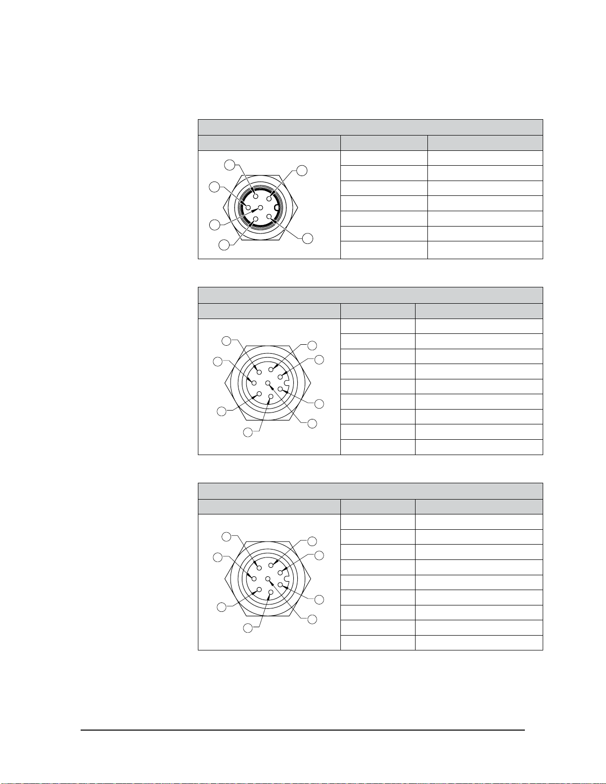
3.3.1.1 Axia80 6-Pin M8 Male Connector
Table 3.2—Axia80 Sensor Connector, M8, 6-pin, Male
Connector Schematic Pin Number Signal
1
2
6
3
4
5
1 Tx +
2 Tx -
3 Rx +
4 Rx -
5 V +
6 V - / 0 V / Ground
Shell Shield
3.3.1.2 Axia80 and Axia90 8-pin M8 Male Connector
Table 3.3—Axia80 and Axia90 Sensor Connector, M8, 8-pin, Male
Connector Schematic Pin Number Signal
1
6
2
8
4
5
3
7
1 Reserved
2 V +
3 V - / 0 V / Ground
4 Tx -
5 Rx +
6 Tx +
7 Reserved
8 Rx -
Shell Shield
3.3.1.3 Axia130 8-pin M12 Male Connector
Table 3.4—Axia130 Sensor Connector, M12, 8-pin, Male
Connector Schematic Pin Number Signal
1
6
2
8
4
5
3
7
1 Reserved
2 V +
3 V - / 0 V / Ground
4 Tx -
5 Rx +
6 Tx+
7 Reserved
8 Rx -
Shell Shield
Manual, F/T Sensor, Ethernet Axia
Document #9620-05-C-Ethernet Axia-02
Pinnacle Park • 1031 Goodworth Drive •Apex, NC 27539 • Tel:+1 919.772.0115 • Fax:+1 919.772.8259 • www.ati-ia.com
C-16
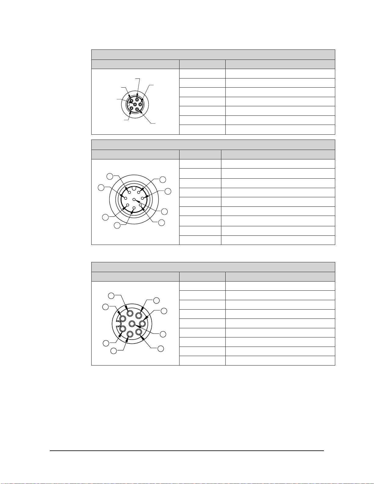
3.3.2 Axia80SensorCable(P/N9105-C-ZC22-ZC28-X)
Table 3.5—ZC22Connector,M8,6-pin,Female
Connector Schematic Pin Number Signal
1
2
3
4
5
6
1 Tx +
2 Tx -
3 Rx +
4 Rx -
5 V +
6 V - / 0 V / Ground
Shell Shield
Table 3.6—ZC28Connector,M12,8-pin,Male
Connector Schematic Pin Number Signal
1
2
3
456
7
8
1 Reserved
2 V +
3 V - / 0 V / Ground
4 Tx -
5 Rx +
6 Tx +
7 Reserved
8 Rx -
Shell Shield
3.3.3 Axia80andAxia90SensorCable(P/N9105-C-ZC27-ZC28-X)
Table 3.7—ZC27Connector,M8,8-pin,Female
Connector Schematic Pin Number Signal
1
2
34
5
7
8
6
1 Reserved
2 V +
3 V - / 0 V / Ground
4 Tx -
5 Rx +
6 Tx +
7 Reserved
8 Rx -
Shell Shield
Manual, F/T Sensor, Ethernet Axia
Document #9620-05-C-Ethernet Axia-02
Pinnacle Park • 1031 Goodworth Drive •Apex, NC 27539 • Tel:+1 919.772.0115 • Fax:+1 919.772.8259 • www.ati-ia.com
C-17
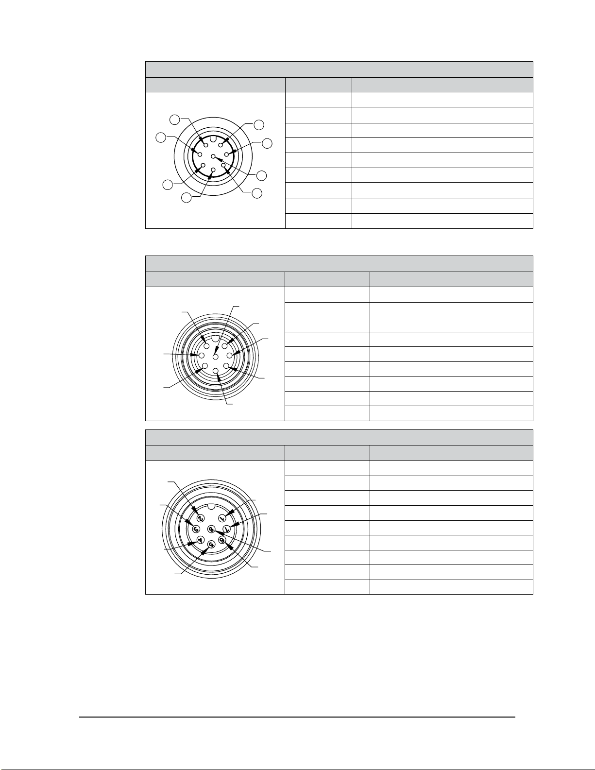
Table 3.8—ZC28Connector,M12,8-pin,Male
Connector Schematic Pin Number Signal
1
2
3
456
7
8
1 Reserved
2 V +
3 V - / 0 V / Ground
4 Tx -
5 Rx +
6 Tx +
7 Reserved
8 Rx -
Shell Shield
3.3.4 Axia130SensorCable(P/N9105-C-ZC28-ZC28-X)
Table 3.9—ZC28Connector,M12,8-pin,Female
Connector Schematic Pin Number Signal
12
3
4
5
6
7
8
1 Reserved
2 V +
3 V - / 0 V / Ground
4 Tx -
5 Rx +
6 Tx +
7 Reserved
8 Rx -
Shell Shield
Table 3.10—ZC28Connector,M12,8-pin,Male
Connector Schematic Pin Number Signal
3
4
1
2
56
7
8
1 Reserved
2 V +
3 V - / 0 V / Ground
4 Tx -
5 Rx +
6 Tx +
7 Reserved
8 Rx -
Shell Shield
Manual, F/T Sensor, Ethernet Axia
Document #9620-05-C-Ethernet Axia-02
Pinnacle Park • 1031 Goodworth Drive •Apex, NC 27539 • Tel:+1 919.772.0115 • Fax:+1 919.772.8259 • www.ati-ia.com
C-18
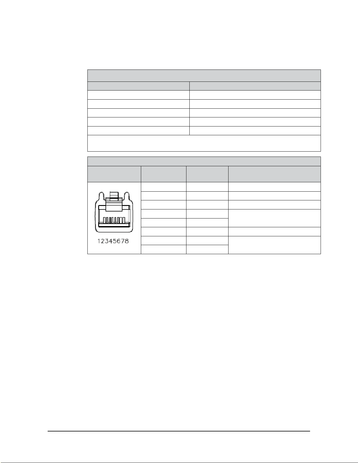
3.3.5 EthernetCable(P/N9105-C-ZC28-U-RJ45S-X)
This cable has (2) branches: an unterminated end for power and an RJ45 connection for Ethernet.
Both of these connections connect to the customer’s device. For the signals and corresponding pin
numbers/wire color, refer to the following sections.
Table 3.11—Branch1,UnterminatedEndForPower
WireJacketColor Signal
Braided Metal Shield Shield (Connect to Ground)
Brown V+
Brown/White V - / 0 V / Ground
Blue/White (TP1 +)1Reserved
Blue (TP1 -)1Reserved
Note:
1. Reserved-not used.
Table 3.12—Ethernet Connector, RJ45, 8-pin, Female
Connector
Schematic Pin Number Wire Color Signal
1 White/Orange Tx +
2 Orange Tx -
3 White/Green Rx +
4 - No Connection
5 -
6 Green Rx -
7 - No Connection
8 -

Manual, F/T Sensor, Ethernet Axia
Document #9620-05-C-Ethernet Axia-02
Pinnacle Park • 1031 Goodworth Drive •Apex, NC 27539 • Tel:+1 919.772.0115 • Fax:+1 919.772.8259 • www.ati-ia.com
C-19
4. ConnectingThroughEthernet
Different methods for setting an IP address and how to congure a Windows® 7/8/10 operating system to connect
the sensor to the ATI Ethernet Axia sensor webpages, are covered in the following sections.
For a sensor to connect through Ethernet, a user must congure the IP address setting of the sensor. The sensor can
connect through Ethernet by one of the following options:
• Plug the end of the Ethernet cable into a port of an Ethernet switch that is connected to a computer.
NOTICE:
• If the computer does not have a spare Ethernet port, an additional port must be installed. Users
should contact their IT department for assistance.
4.1 IPAddressCongurationforEthernet
To apply new IP address settings, power cycle the sensor. New IP address settings are only loaded upon
power up. Congure an IP address for the Ethernet Axia sensor with one of the following methods:
Method 1: Set the IP address to a static value stored on the Communication Settings
webpage. (refer to Section 4.2—Connecting To the ATI Webpages Using a Windows
Computer steps 11 through 12)
Method 2: The DHCP server assigns an IP address. Enable this option in the Ethernet Axia’s
webpages (refer to Section 4.2—Connecting To the ATI Webpages Using a Windows
Computer steps 11 through 12). To use this method, a DHCP server must be present
in the network.
ATI ships the sensor with DHCP enabled and the static IP address set to 192.168.1.1. If the network does not
support DHCP, the network automatically uses the static IP address. If a LAN connection is absent during
power up, the network does not use DHCP. Users should contact their IT department for more information.

Manual, F/T Sensor, Ethernet Axia
Document #9620-05-C-Ethernet Axia-02
Pinnacle Park • 1031 Goodworth Drive •Apex, NC 27539 • Tel:+1 919.772.0115 • Fax:+1 919.772.8259 • www.ati-ia.com
C-20
4.2 ConnectingTotheATIWebpagesUsingaWindowsComputer
To initially access the ATI Ethernet Axia F/T webpages, congure the sensor to work on the network by
assigning an IP address and provide basic information about the network.
For the initial connection, directly connect the computer to the sensor and disconnect from LAN. The
sensor’s default IP address is 192.168.1.1. Temporarily change the computer’s Ethernet adapter to a static IP
address with the same rst three elds as the sensor, for example: 192.168.1.100.
NOTICE: If the computer has multiple connections to Ethernet, such as a LAN connection and a
wireless connection, select the LAN that will be connected to the Ethernet Axia sensor.
NOTICE: If the sensor’s static IP address has been changed and is no longer set to the default,
thecomputer’sEthernetadaptermustbesettoastaticIPaddresswiththesamerstthree
eldsastheNEWsensorIPaddress.Asanexample,192.168.1.100worksifthesensorisusing
the default IP address of 192.168.1.1.
1. Disconnect the Ethernet cable from the LAN port on the computer.
2. Open the computer’s Internet Protocol (TCP IP) Properties window:
• For Windows® 7/8/10 operating system, complete the following steps:
a. From the Start menu, select the Control Panel.
b. Click on the Network and Internet icon.
c. Click on the Network and Sharing Center icon.
d. Click on the View network status and tasks link.
e. Click on the Local Area Connection link.
f. A new window opens that displays the general settings for that local area connection link.
Click on the Properties button.
g. On the Networking tab, scroll down and select Internet Protocol Version 4 (TCP/IPv4)
connection item (refer to Figure 4.1).
h. Click on the Properties button (refer to Figure 4.1).
Figure4.1—Windows7/8/10NetworkingInformation
3. Record the values and settings shown in the properties window. Save these values so that the computer
can be returned to its original conguration.
Other manuals for ATI Axia80
1
This manual suits for next models
2
Table of contents
Other Novanta Accessories manuals


