Novanta JADAK THINGMAGIC EL6E User manual
www.JADAKtech.com
GETTING STARTED WITH THE THINGMAGIC®
EL6E SMART MODULE
EL6e Development Kit Hardware
Included Components
The EL6e development kit contains:
• 1 x EL6e USB module
• 2 x Antennas (one for North America region range and one for EU region range)
• 1 x USB cable with 13-pin connector
• 1 x USB “Y” cable adapter
• 1 x Pack of sample RFID tags
• 4 x Antenna mounting hardware
• 4 x Stand-offs to protect the EL6e when used on a desktop or conductive surfaces
NOTE: Some of these parts cannot be ordered separately.
Set up the Development Kit
1. Select the antenna to use. When operating the EL6e Module, you will need to select a region of operation.
These regions will either be in the EU range (865 to 869 MHz) or the “NA” region (915 to 928 MHz). Using the
inappropriate antenna for your region setting results in poor performance and may shorten the life of the module
over time.
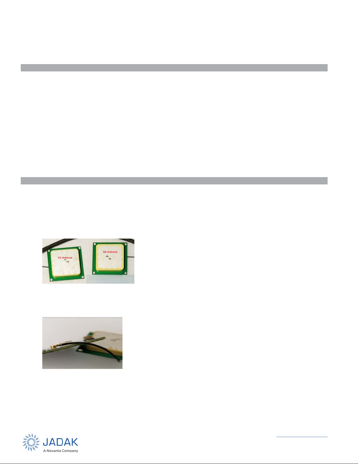
2. The EU antenna is marked 867M. The NA antenna is marked 924.5M. If the marking on the antennas are not
visible, they can be distinguished from one another by the appearance of the silver area, as shown below.
3. Carefully attach the U.FL connector on the antenna cable to the mating connector on the board. The cable
should be free to rotate around the connector without disconnecting.
NOTE: It is very difficult to re-seat this connector once the antenna is mounted on the board.

Getting Started - EL6 USB Dev Kit User Guide 2
www.JADAKtech.com
4. Rotate the antenna and cable above the board until the RF cable is oriented as shown below. Any other
orientation of antenna to the board will cause the components on the bottom of the antenna to interfere with
those on the top of the board.
5. Use the nylon hardware to mount the antenna to the board in 4 locations, as shown below.
6. Use the nylon stand-offs to affix the feet at the 4 corners of the board as shown below, with the screw on top
and the stand-off on the bottom. This will prevent components from shorting out on the surface below the board
if that surface is conductive.
7. Attach the USB cable to the 13-pin connector on the board. Make sure the side of the connector faces up (as
shown below), with the wires entering the connector as shown.
8. Attaching the USB “Y” Cable to the end of the USB cable to the board is optional. When attached, the black
USB end is connected to the host PC and the red end may optionally be connected to a second USB port (or a
USB charging plug) to provide extra DC power should a single DC power of the port on the PC host be
insufficient to power the module when the module is transmitting at its highest RF power levels. The default
settings do not require use of the USB “Y” cable.

Getting Started - EL6 USB Dev Kit User Guide 3
www.JADAKtech.com
9. The Assembled Development Kit should look like this:
.
Communicate with the Development Kit
The first step to enabling communication between the host PC and the EL6e board is to install the USB Driver (if
necessary). For Windows 10 operating systems, no additional driver is required. USB will be detected automatically
after plugging in the USB cable.
Install the USB Driver
For Windows 10 operating systems, no additional driver is required. USB is automatically detected after plugging in
the USB cable. If the automatic detection fails, follow these steps to recognize the EL6e module:
1. Plug the EL6e module USB cable into the PC.
2. Windows should report it has Found New Hardware and open the Hardware Installation Wizard.
3. Select Install from a list or specific location (Advanced). Click Next.
4. Select Don’t search… Click Next, then Next again.
5. Click Have Disk and navigate to where the SDK zip is extracted. Select EL6e.inf under the drivers folder. Click
Open, then OK.
6. A COM port should now be assigned to the EL6e. If you aren’t sure what COM port is assigned you can find it
using the Windows Device Manager.
In order to use the USB interface with a Windows 7 operating system, you must first install the EL6e.inf file,
available in the SDK download package.
1. Right click Computer on the Start Menu and select Manage.
2. Select Device Manager.
3. Select Elara reader and click on Update Drivers.
4. Click on Browse my computer for driver software.
5. Click on Let me pick from a list of available drivers on my computer.
6. Click on Have Disk.

Getting Started - EL6 USB Dev Kit User Guide 4
www.JADAKtech.com
7. Provide the .inf file path.
8. Proceed with the driver installation.
Connecting the EL6e module
1. By default, the module behaves like an additional keyboard and “type” any tag information it sees. Before con-
necting the module, either clear all tags away from the vicinity, or bring up an application to display tag data as
it comes in, such as Windows Notepad. Otherwise, the module will output tag ID characters into any open appli-
cation.
2. Plug the USB connector into your PC. When the multicolor Status LED at bottom right side of the module turns
green, the module has successfully connected to the host machine. If it is green and flashing, the module is
attempting to read tags. If green and steady, it is operational, but not attempting to read at that time.
Two quick presses of the CapsLock key will cause module to start or stop reading tags. The green LED indicates
the state of the module if you forget how many times you double clicked on the CapsLock key.
By default, the EL6e module reports any tags it sees within a distance of about ½ meter (approximately 1.5 feet) at
a rate of one report per second.
NOTE: The read distance varies widely depending on the tag used. The module can be configured to read at
shorter or greater distances than the default setting.
Advanced Operation
By default, the EL6e module presents two interfaces to the PC:
• USB Keyboard Emulation (also called HID or Keyboard Wedge) interface.
• USB Serial interface on a COM port that supports two-way communication with the module via an industry
standard RAIN protocol.
JADAK supplies a GUI-based tool to demonstrate the capabilities of the EL6e module. The Installer for this
ThingMagic Configuration Tool is distributed in the EL6e SDK.
The ThingMagic Configuration Tool allows you to:
• Configure the EL6e Module.
• Save settings so they are retained across a reboot.
• View tag read results from either the keyboard interface or COM interface.
• Upgrade the operational firmware on the EL6e module (a new Elara SDK is distributed with each firmware
update.
• Log and view all communications with the module (Transport Log) to troubleshoot issues or learn the RAIN
protocol so you can implement your own command and control applications.
The Elara SDK also contains code samples to help developers create command and control applications that utilize
the RAIN interface.
For additional information, consult the EL6e User Guide. It is found in the Elara section of the JADAK Support
website, www.jadaktech.com/documentation/rfid/el6e/.
For support, contact your reseller or [email protected], as appropriate.
Warning: While the module is powered up, do not touch components. Doing so may damage
the Development Kit and EL6e module.
TM_EL6-QSG Rev 03182019
Table of contents
Popular Control Unit manuals by other brands

Kontron
Kontron CP-RIO3-04S user guide

Orbinox
Orbinox MP User's manual and maintenance guide

Cross Technologies
Cross Technologies 1586-04-0431 instruction manual

Spectrum Controls
Spectrum Controls Micro 800 user manual

Velocity
Velocity VL-ZMB installation instructions

Ogden
Ogden ETR-9040 instruction manual


