NovaTec Bessemer C Series User manual

Rotary Knife Cutter
Model: Bessemer C-Series:
C-2, C-3 & C-4
© NOVATEC, INC 2015 All Rights Reserved
C Series IM 12 MAY 2015

C-Series IM 12 MAY 2014
Please record the following information,
which is specific to this piece of
equipment, in the space provided.
Our Parts/Service Department will need
these numbers to properly respond to
any of your requests.
Instruction Manual: C-Series IM 12 MAY 2015
Model #:___________________________
Serial #____________________________
DISCLAIMER: NOVATEC, Inc. shall not be liable for
errors contained in this Instruction Manual nor for
misinterpretation of information contained herein.
NOVATEC shall not, in any event, be held liable for any
special, indirect or consequential damages in
connection with performance or use of this information.
© 2015 NOVATEC Inc. All Rights Reserved Document: C-Series IM 12 MAY 2014

C-Series IM 1 MAY 2014
Table of Contents
1PURPOSE OF THIS MANUAL ............................................................................................................3
Explanation of Symbols...........................................................................................................................................3
2SAFETY PRECAUTIONS AND WARNINGS......................................................................................4
2.1 Safe Access to Guarded Blade Area ................................................................................................................4
3.0 GENERAL DESCRIPTION .................................................................................................................. 5
4.0 SPECIFICATIONS............................................................................................................................................6
4.1 Product Features........................................................................................................................................6
5.0 BLADE SPEED VS CUTS PER MINUTE.........................................................................................................7
6.0 OPERATING PRINCIPLES....................................................................................................................9
7.0 INSTALLATION......................................................................................................................................9
7.1 Mechanical Installation....................................................................................................................................10
7.1.1 The Blades ..........................................................................................................................................10
7.1.2 The Bushing ........................................................................................................................................11
7.2 Electrical Installation .......................................................................................................................................12
8.0 INDICATOR LIGHT DESIGNATIONS.................................................................................................. 14
9.0 PLC GENERAL OVERVIEW................................................................................................................ 15
9.1 Startup and Power Loss..................................................................................................................................15
10.0 SCREEN CONVENTIONS AND COMMON ELEMENT.....................................................................15
10.3 Screen Title...................................................................................................................................................16
10.4 Machine Status .............................................................................................................................................16
10.5 Standard Navigation Buttons ........................................................................................................................16
10.6 Cut Start/Stop Buttons ..................................................................................................................................16
11.0 SYSTEM STARTUP ...........................................................................................................................17
11.1 Initial Screen - ...............................................................................................................................................17
11.2 POWER UP Screen ......................................................................................................................................17
11.2.1 Verify Safety/Reset System...............................................................................................................17
11.2.2 Verify Safety/Press E-Stop................................................................................................................18
11.2.3 Reset System to Home Screen.........................................................................................................18
11.2.4 Homing Screen..................................................................................................................................18
12.0 MACHINE OPERATION.....................................................................................................................19
12.1 Quick Ops Screen Items...............................................................................................................................19
12.2 Cut Start/Stop Buttons ..................................................................................................................................20
12.3 Changing the CUT MODE ............................................................................................................................20
12.4 Recipe Select Screen....................................................................................................................................21
12.5 CURRENT RECIPE SCREEN............................................................................................................22
12.6 Setting Up Counters......................................................................................................................................23
12.7 Production Metrics ........................................................................................................................................23
12.8 QUICK OPS SCREEN VERSIONS ....................................................................................................24
1
© 2015 NOVATEC Inc. All Rights Reserved Document: C-Series 7 MAY 2015

C-Series IM 1 MAY 2014
13.0 SETUP SCREENS.............................................................................................................................. 26
13.2 LOGON .........................................................................................................................................................26
13.3 Home Screen................................................................................................................................................27
13.4 Recipe Functions ..........................................................................................................................................28
13.5 SETUP SCREEN 1.......................................................................................................................................29
13.6 SETUP Screen 2...........................................................................................................................................30
13.7 SETUP Screen 3...........................................................................................................................................32
13.8 Servo Setup Page.........................................................................................................................................34
13.9 Batch Counter Screens................................................................................................................................36
14.0 MAINTENANCE..................................................................................................................................37
At Startup ..............................................................................................................................................................37
Every bushing or blade change ............................................................................................................................37
Daily ......................................................................................................................................................................37
Every 3 Months .....................................................................................................................................................37
15.0 WARRANTY – NOVATEC, INC. - EFFECTIVE DATE 6-12-2012.....................................................38
2
© 2015 NOVATEC Inc. All Rights Reserved Document: C-Series 7 MAY 2015

C-Series IM 1 MAY 2014
1 PURPOSE OF THIS MANUAL
This manual describes the installation and operation of the NOVATEC Model C Rotary Knife Cutter.
Before installing this product, please read this guide and any additional guides associated with the
system’s auxiliary equipment.
Explanation of Symbols
This manual includes both general and task-specific safety precautions. These precautions
are highlighted in the manual by the following categories:
WARNING: This symbol identifies situations that are potentially
hazardous to personnel or equipment.
NOTE Highlights information provided in text or procedures. This
information may or may not be related to safety.
3
© 2015 NOVATEC Inc. All Rights Reserved Document: C-Series 7 MAY 2015

C-Series IM 1 MAY 2014
2 SAFETY PRECAUTIONS AND WARNINGS
These operating instructions must be read, understood, and implemented by all personnel
responsible for this system.
All mechanical and electrical work must be performed by qualified personnel only.
Always disconnect power before servicing.
Refer to the machine serial number nameplate and drawings supplied with this system for
actual power requirements.
Be sure to install the equipment with the proper electrical connections according to all national
and local regulations.
Electric power supply should be through a separate disconnect switch with properly sized
overload/fuse protection.
The customer is required to operate the equipment with all safety features in proper working
condition.
NOVATEC shall provide no further guarantee for function and safety in the event of
unauthorized modifications.
2.1 Safe Access to Guarded Blade Area
It is safe to access the guarded blade area when the power is on. NOVATEC Cutters use
a servo that has built in safety. It can execute a Safe Stop on E-Stop and has a Safe Torque
Off which is executed within 0.5 seconds of E-Stop. It also is monitoring itself for Safe
Standstill which is interlocked to the guard lock. With the addition of redundant safety relays,
motor contactor and guard interlock, the system can exceed SIL-3, PL-d safety requirements
for a Cat3 safety hazard.
NOTE: Additional guarding may be required where the product enters and exits the
bushing.
NOTE: The Safety Circuit Must Be Tested on 90 Hour Intervals
To meet the requirements for a Cat3 safety system, the safety circuit must be tested at regular
intervals to insure that it is functioning properly. When the system is first powered on, the
power must be engaged and then the E-Stop activated to ensure that it is functioning. After
90 hours of continuous operation a Warning Message will appear instructing the operator to
perform the safety verification test which involves pressing the E-Stop and the resetting the
circuit. Production can continue while the message is present but arrangements should be
made to perform the test as soon as possible.
Even though there is no power to the blade when the system is E-Stopped, there is still the
hazard of the sharp blade. Care should always be taken when working in this area.
Please contact Novatec if there are any questions or concerns.
4
© 2015 NOVATEC Inc. All Rights Reserved Document: C-Series 7 MAY 2015

C-Series IM 1 MAY 2014
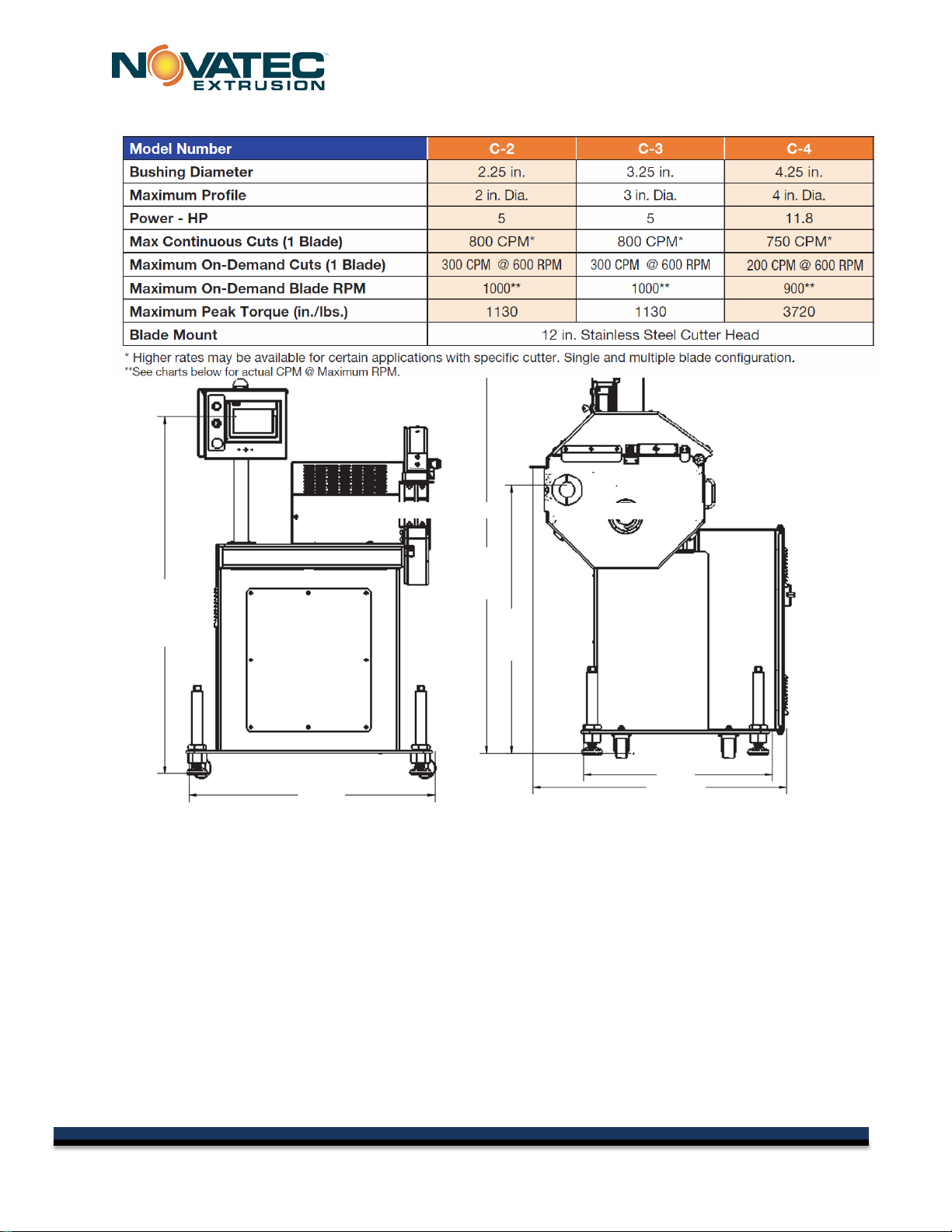
3.0 GENERAL DESCRIPTION
The NOVATEC, C Series Rotary Knife Cutter offers high versatility to cut a wide range of profiles. It
is able to cut small profiles at high speeds and large profiles at lower speeds. Extrudate is fed into
the cutter from upstream, typically by a puller. Two cutter bushings, on either side of the knife, guide
the extrudate through the cutter. A rotary knife is mounted to a 12” diameter cutter head and driven
by a servo motor through a gear reducer. This knife cuts material that is supported between the
bushings. The knife is positioned at a home position until the cut motion begins. The knife then
rotates through a cutting lubricant/chip collection reservoir, through a felt blade wipe to clean the
blade, and then through the bushings again to make another cut. The cut extrudate continues to
move through the bushing where it is either collected or is conveyed further downstream by an
optional conveyor.
Two cutting modes are available: ON-DEMAND cutting mode and CONTINUOUS cutting mode.
Within these two major modes of operation, a wide range of parameters may be adjusted for
consistent, repeatable, and precise results.
•ON-DEMAND cutting mode allows 250 cuts per minute. The blade does not continuously
rotate, but instead starts and stops as needed.
•CONTINUOUS cutting mode allows up to 750 cuts per minute by continuously rotating the
cutter head at a speed sufficient to cut the desired length at the measured line speed.
5
© 2015 NOVATEC Inc. All Rights Reserved Document: C-Series 7 MAY 2015
C-Series IM 1 MAY 2014
52.37” Floor
to
C.L Control
36 “
28
”
58 5
39 9
37 7
4.0 SPECIFICATIONS
4.1 Product Features
•12” high torque cutter head
•Accepts rectangular bushings 19.75mm thick x 89.75mm wide x 150mm long
•Apex Dynamics 4:1 speed reducer
•Taper lock shaft bushing hardware
•2500 count quadrature cut length encoder with 12” circumference measuring wheel
•Knife thicknesses of .015, .020”, .025”, .030”, .040” available; Blades shaped and sharpened
to meet custom application requirements
•Safety interlocks provided for operator safety
•Removable cutting chamber cover with integral reservoir provides full access to cutting
chamber and cutting fluid reservoir
•Split clamp bushing arrangement provides easy bushing setup
•Indicator lights for machine status indication
•5-Year Warranty
6
© 2015 NOVATEC Inc. All Rights Reserved Document: C-Series 7 MAY 2015

C-Series IM 1 MAY 2014
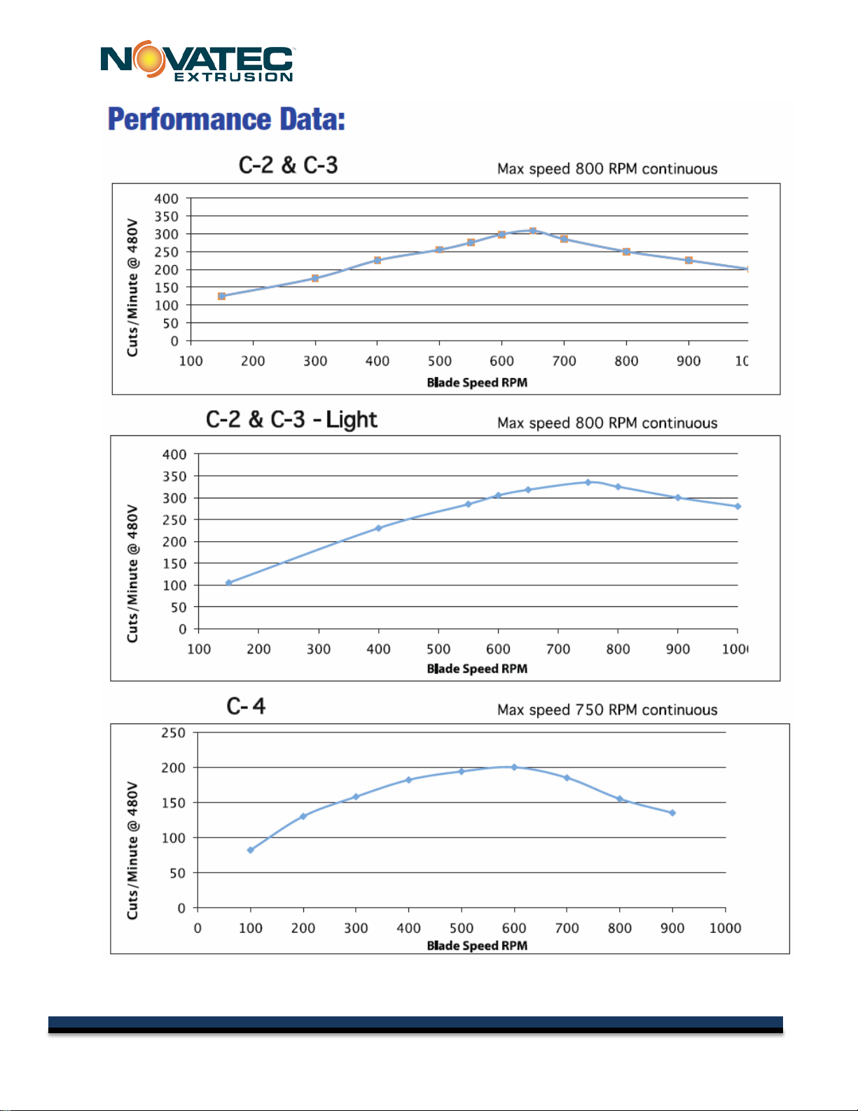
5.0 BLADE SPEED VS CUTS PER MINUTE
The blade speed can be set anywhere from the Minimum On Demand Blade Speed to the
Maximum Blade Speed set on the System Setup page. Typically, the blade speed will be set
so that the product has the best possible cut. If the blade speed is set too low and the CPM
requirement is too high, the blade will not travel around in time to start the next cut and the
next cut will be ignored resulting in a part that is twice as long as intended. It is also possible
to set the On Demand Blade Speed and the Required CPM so high that eventually, it faults
the drive because there is too much power required for the move. Below are charts that show
the blade speed versus CPM for several cutters. It was determined by shop testing. Actual
results might be less due to lower supply power or higher ambient temperatures.
The tests were performed with 480VAC at 75F.
7
© 2015 NOVATEC Inc. All Rights Reserved Document: C-Series 7 MAY 2015
C-Series IM 1 MAY 2014
8
© 2015 NOVATEC Inc. All Rights Reserved Document: C-Series 7 MAY 2015

C-Series IM 1 MAY 2014
6.0 OPERATING PRINCIPLES
The NOVATEC Model C rotary knife cutter model C is used to cut lengths of plastic extrudate. In
either the ON DEMAND or CONTINUOUS MODE.
ON DEMAND MODE: Plastic extrudate is fed through two inline bushings, which guide the plastic
through the cutter. The instant of cutting can be determined by a sensor, length of time or an
Encoder. Once the signal is sent to the PLC, the PLC processes the request and initiates the cut. A
servomotor rapidly accelerates the cutter head with attached blade(s) to rotate either 180° or 360°,
slicing through the extrudate. The cutter head then returns to its home position and waits for another
cut signal from the PLC.
CONTINUOUS MODE: Plastic extrudate is fed through two inline bushings, which guide the plastic
through the cutter. The instant of cutting can be determined by a length of time or an Encoder. Once
the signal is sent to the PLC, the PLC processes the request and initiates the cut. A servomotor
continuously rotates the cutter head with attached blade(s), slicing through the extrudate. The cutter
head rotates continuously at a speed sufficient to cut the desired length at the measured line speed.
7.0 INSTALLATION
1. Carefully unpack the cutter and any other components delivered with it. Check all
packaging for loose parts, documentation, and other included items. Carefully inspect the
cutter. Ensure that no wires, bolts, screws, terminals, or other connections have come
loose during shipping. Check to ensure that all moving parts are not obstructed by debris
or excess packing material.
2. You may require the following tools to complete the installation:
a. 16” or 18” adjustable wrench
b. Feeler gauges
3. All national and local electrical, building, and safety codes need to be followed. Proper
grounding of all equipment is important. Check the electrical wiring schematic for wiring
numbers and details. The following paragraphs describe installation of typical system
components. Some of them are optional and may not be required for your system.
CAUTION: All machines must be grounded to prevent "shocks" from
static electricity that is generated by some materials as they are moved.
This is an extremely important step.
All electronics are susceptible (to varying degrees) to electrostatic damage
and, although as much protection as possible has been designed into the
system; this cannot completely eliminate upsets due to electrostatic voltage
being accidentally introduced into the electronic circuitry.
9
© 2015 NOVATEC Inc. All Rights Reserved Document: C-Series 7 MAY 2015
C-Series IM 1 MAY 2014
7.1 Mechanical Installation
Determine the position of the cutter. This should be done with consideration to the location of
the adjacent puller and to the nature of the extrudate. For flexible and semi-flexible extrudate,
locate the cutter closer to the puller to minimize extrudate buckling during a cut. For rigid
extrudate, allow more space between cutter and puller to improve cut finish quality and
consistency.
Once the general position has been determined, carefully align the cutter with the extrusion
line. It is easiest to adjust the position on the floor before adjusting to the proper height.
Ensure that all downstream equipment is properly aligned (pullers, tanks, etc.). To adjust the
centerline height of the cutter, adjust each foot pad at the corners of the base of the cutter with
a 16 or 18 inch adjustable wrench. Ensure that the cutter is level.
7.1.1 The Blades
When installing the cutter blades, great care should be taken to avoid being cut. Use cut-
resistant gloves to avoid injury. Wait until the knife assembly fully stops before opening the
inspection door.
Ensure the cutter has stopped rotating; rotate the key switch clockwise (to 2 o’clock) and wait
5 seconds for the door to unlock; open the bushing guard (yellow cover).
Rotate the cutter head to a point where the hole in the
Cutter head, lines up with a hole in the cutter enclosure.
Insert an Allen wrench through the two holes to hold the
cutter head in place.
This avoids the possibility that the cutter head will move while
loosening/tightening bolts.
Remove the bolts holding the counter-balance or the old
blade(s), remove counter balance or the old blade(s), and
fasten new blade(s) in the same way the old blade was
attached.
Check that the new blade fully extends through the bushing so that the entire product is cut.
Tighten the knife-securing hardware to 140 inch-pounds of torque.
Always check the blade(s) to bushing clearance after
installing a new blade(s) by rotating the cutter head
manually and inspecting the gap between each of the
bushings and the blade(s).
Ensure that the blade(s) moves freely through the
bushings and that the bushings are properly
10
© 2015 NOVATEC Inc. All Rights Reserved Document: C-Series 7 MAY 2015
C-Series IM 1 MAY 2014
secured before re-powering the machine.
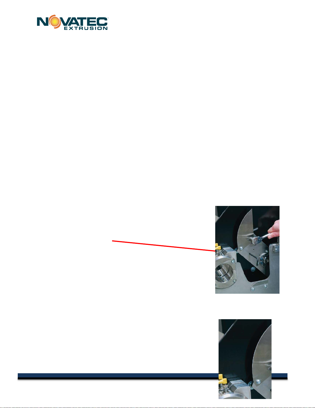
7.1.2 The Bushing
Ensure the cutter has stopped rotating; rotate the key switch clockwise to “UNLOCK”
(2 o’clock) and waiting 15 seconds for the door to unlock before opening the bushing guard
(yellow cover). Loosen the rectangular bushing by loosening the12mm socket head set screw
located on the top of each cylindrical bushing holder. Test the location of the bushings for
accuracy by retightening the bushing holder socket head set screw and manually rotating the
cutter head to ensure that the blade passes through the two bushings. When satisfied with
the fit, fully retighten the bushing holder, inspect the blade clearance an additional time and
make sure the cutter head can rotate a full revolution while clearing the bushings. During
initial set up, the cylindrical bushing holders should be adjusted relative to one another by
loosening the socket head cap screws on the front of the machine that clamp the bushing
holders in place. This adjustment ensures the rectangular bushing holders are rotationally
aligned about the axis of the cylinder.
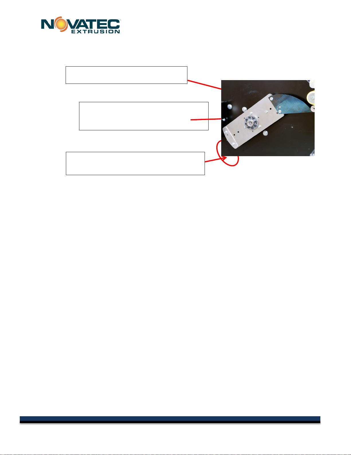
NOTE: Counter-balance weight, opposite the
blade, must remain bolted in place if only one
blade is used.
NOTE: Counter-balance should be
removed on end where blade is installed.
NOTE: When a single blade is installed, it
must be installed on same end of cutter
head as the HOME SENSOR is installed.
11
© 2015 NOVATEC Inc. All Rights Reserved Document: C-Series 7 MAY 2015

C-Series IM 1 MAY 2014
7.2 Electrical Installation
Always disconnect and lock out the main power supply before wiring power and control cables
between the NC rotary knife cutter controller and the external devices. Refer to the wiring
diagram and general arrangement drawings supplied with this system before making electrical
connections.
Use shielded cable for communications wiring.
Keep communication cables and control wiring as far as possible from high voltage
equipment. If you must run cable across power lines, run the cable at right angles to the
line.
Ensure the equipment grounding is properly connected. Shielded cable should be
grounded at one end only and is typically grounded in the main I/O enclosure.
WARNING: Do not install communication cable where it will
come into contact with any buildup of electrical charge!
It may be tempting to run the wire next to the material conveying
lines, but a substantial buildup of electrical charge can and will occur,
especially with certain types of plastic resins and, if the conveying
lines are not grounded, they can arc to the cable disrupting
communications and/or possibly causing damage.
Open the cutter’s electrical enclosure and insert the main power through a knockout in the
wall of the enclosure. Connect the power wire as indicated on the included wiring diagram.
Check that all terminal screws are secure. Close electrical enclosure.
12
© 2015 NOVATEC Inc. All Rights Reserved Document: C-Series 7 MAY 2015
C-Series IM 1 MAY 2014
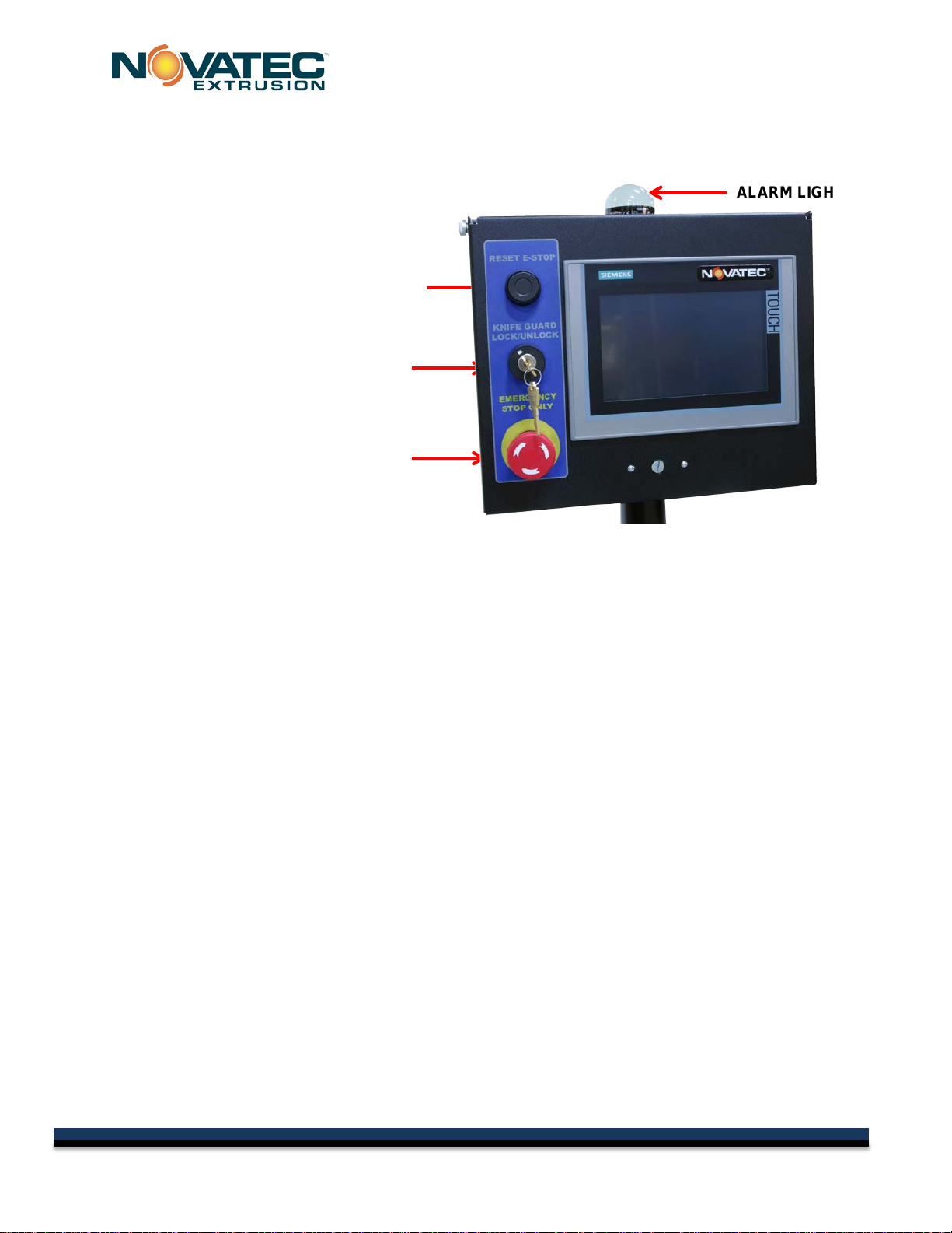
Before testing the machine, confirm that the placement and wiring of the cutter conform to all
applicable national and local regulations. When ready, turn on the main disconnect. Make
sure that the E-Stop button is in the out position. Press the reset button.
KNIFE GUARD
LOCK/UNLOCK
EMERGENCY STOP
RESET
EMERGENCY STOP
ALARM LIGHT
13
© 2015 NOVATEC Inc. All Rights Reserved Document: C-Series 7 MAY 2015

C-Series IM 1 MAY 2014
8.0 INDICATOR LIGHT DESIGNATIONS
The indicator light on top of the operator panel is used for machine alarm and status conditions.
Following is the meaning of those designations.
•Red – Cutter is Faulted
There is a fault condition that has stopped the machine
or powers down the safety circuit.
•Solid Orange – Warning is Present
There is a condition that requires operator attention.
The machine will continue to run.
•Flashing Orange – Blade is Homing
The safety circuit has been powered on and the blade servo is homing.
•Flashing Green – Cutter is Ready
The system is ready to start but is not running. Press the Run Product or Run Scrap button to
start machine.
•Solid Green – Cutter is Running Production
The system is cutting production parts.
•Flashing Green/Orange – Cutter is Running Scrap
The system is cutting Scrap parts.
14
© 2015 NOVATEC Inc. All Rights Reserved Document: C-Series 7 MAY 2015

C-Series IM 1 MAY 2014
9.0 PLC GENERAL OVERVIEW
The NOVATEC, C Series cutters use a Siemens PLC controller to control a servomotor
actuated knife which can be signaled to cut, based on a number of input sensors.
Siemens Operator Interface and Programmable Logic Controller
The Siemens Human Machine Interface (HMI) is a touch-screen viewing and data entry
device, located on the face of the control panel. The screens are graphical in nature and
display information in text and/or by symbol change. The HMI communicates with the internal
Siemens Programmable Logic Controller (PLC) using standard Ethernet protocols.
9.1 Startup and Power Loss
When power is first applied to the Cutter following a power loss, the Cutter will return to the
Quick Ops screen and must be re-initialized. Recipes saved on the device will retain their
settings, and the machine will be in the last state it was in before powered down.
10.0 SCREEN CONVENTIONS AND COMMON ELEMENTS
10.1 Button Borders
Any item which has an operation will appear raised by the use of
shadowing around it to form a border. If the border is grey, then
the current user logged on does not have access to activate the
operation. If the operator presses a button with a grey border a
popup screen will appear prompting them to enter a user name and password. When a button
is pressed, the shadowing on the border will change to indicate to the operator that the system
recognized the button being pressed. Any button or field that has a grey background cannot
be activated. Items will appear on grey backgrounds if they are to report information only or
they are unavailable in the current mode of operation.
10.2 Logon
These two buttons will appear in the top right corner of
every screen. The right button will display "Logon" to
indicate that no one is logged on or it will display the user level of the current person logged
on. Pressing this button will bring up a popup to allow the operator to enter a user name and
password. The button on the left is used to log out and secure the system. It is possible to
change the default user in the machine setup.
15
© 2015 NOVATEC Inc. All Rights Reserved Document: C-Series 7 MAY 2015
C-Series IM 1 MAY 2014
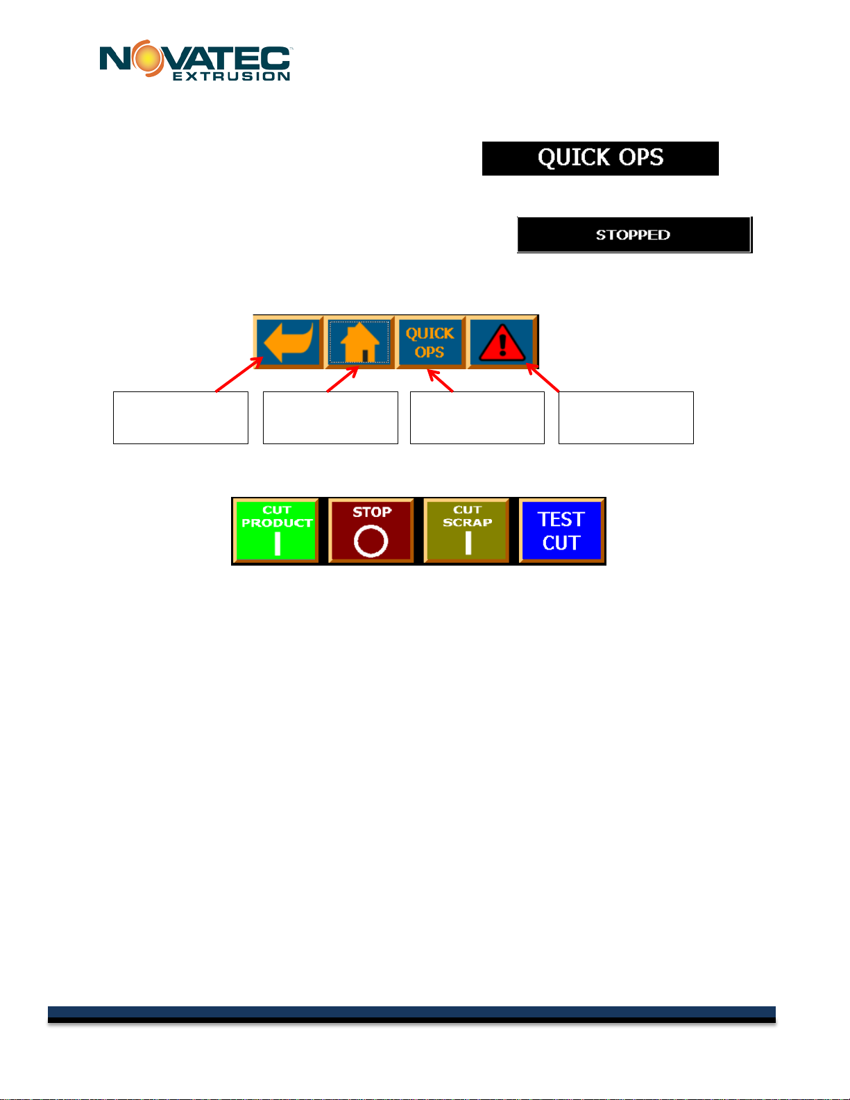
10.3 Screen Title
A Title will appear in the top center or every screen.
10.4 Machine Status
In the top right hand of every screen will be the current
running status of the machine.
10.5 Standard Navigation Buttons
These 4 buttons appear on the bottom of every screen for quick navigation to other screens.
10.6 Cut Start/Stop Buttons
CUT PRODUCT - Press this button to start the cutting of good product using the mode and
setting from the recipe. If the count is enabled, it will count each part as the blade crosses
into it.
STOP - Press this to stop the cutter with the blade at home position
(even in continuous mode).
CUT SCRAP -Press this button to shift to the scrap settings and stop counting.
NOTE: The cutter will quickly and automatically switch between any modes including between
continuous and on-demand cutting. The Cut Scrap button may be hidden in the system setup.
TEST CUT - Press this button to activate a single on-demand test cut. The test cut can be executed
while the system is running on-demand product. It will not be counted and the following cut will be cut
at the proper length/time. If the cut is done very close to when the set on-demand cut needs to
execute, it may interrupt that cut. The method for executing a Test Cut can be set in two ways in the
system setup. It can be set so that a popup menu shows up to confirm the test cut or it can be set so
that the button must be held for 1/2 second before the test cut is executed. This is to prevent
inadvertent test cuts.
NOTE: A Test Cut cannot be executed while the unit is running in continuous mode.
To
Previous Page
To
Home Screen
To QUICK OPS
Screen
To
Alarms Page
16
© 2015 NOVATEC Inc. All Rights Reserved Document: C-Series 7 MAY 2015
C-Series IM 1 MAY 2014
11.0 SYSTEM STARTUP
When powering up the machine, a series of operations must take place to insure that the safety
system is functioning properly. It only needs to be done once on power up.
11.1 Initial Screen -
While the system is booting up the
screen will first be blue with a few icons
and then this initial screen will appear for
about 3 seconds.
If it is not replaced by the screen below
after 15 seconds, there is a problem with
the equipment and it should be looked at
by maintenance.
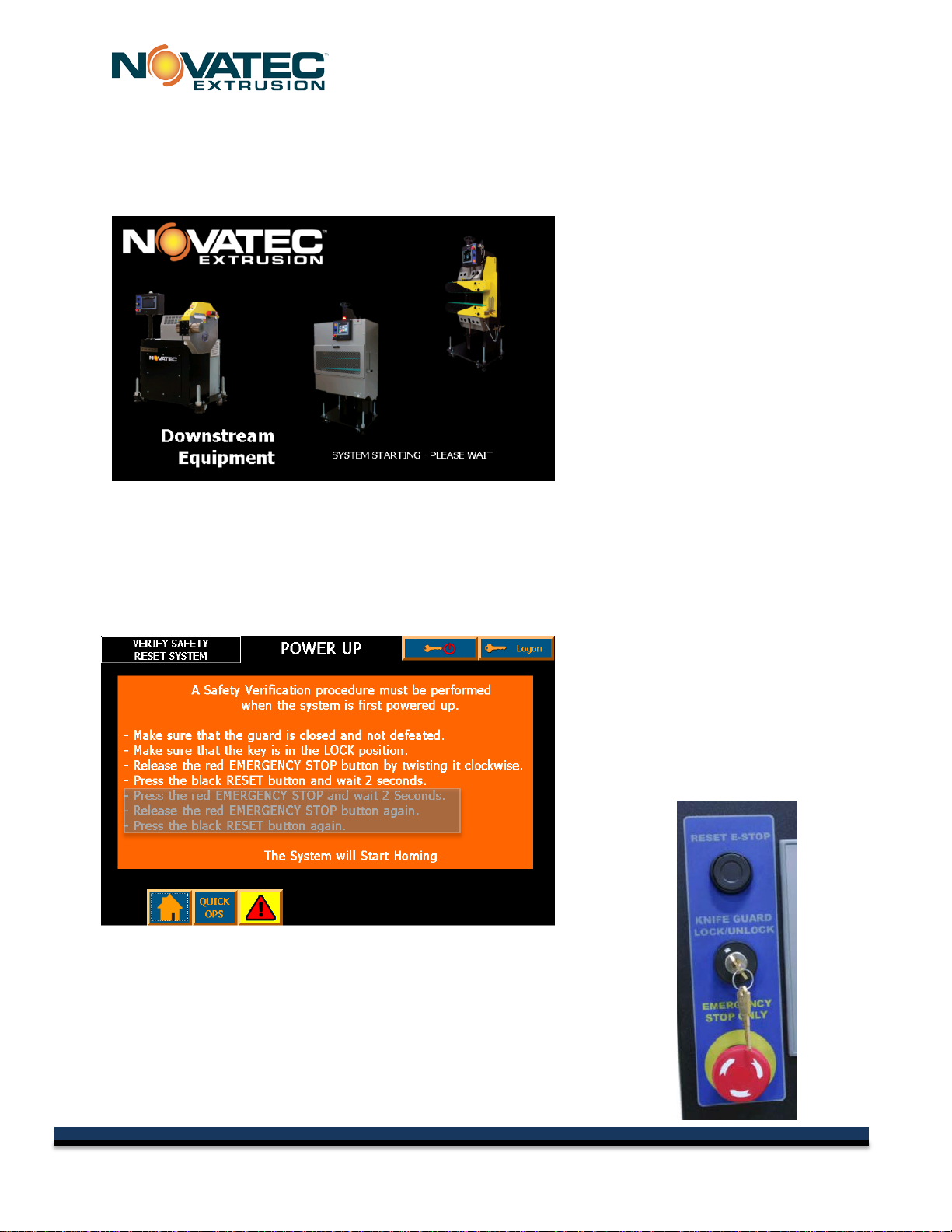
11.2 POWER UP Screen
This screen instructs the operator in the procedure to verify that the safety system is
functioning properly. The operator must first satisfy all of the conditions of the safety circuit.
The first 4 lines of the screen prompt instruct the operator on the procedure.
11.2.1 Verify Safety/Reset System Screen
This screen appears and instructs the
operator in the procedure to verify that
the safety system is functioning properly.
The operator must first satisfy all of the
conditions of the safety circuit.
The first 4 lines of the screen prompt
instruct the operator on the procedure.
17
© 2015 NOVATEC Inc. All Rights Reserved Document: C-Series 7 MAY 2015

C-Series IM 1 MAY 2014
11.2.2 Verify Safety/Press E-Stop Screen
If the operator performed the correct
functions above, the light will blink
orange and this screen appears. The
prompt in the upper left corner instructs
the operator to "PRESS E-STOP".
This tests that the equipment will
respond properly if the E-Stop is pressed
when there is a true emergency.
11.2.3 Reset System to Home Screen
The prompt in the top left corner now
instructs the operator to Reset the
System again by twisting the Red
Emergency Stop button clockwise...AND
pressing the Black RESET button again.
11.2.4 Homing Screen
Homing - The prompt in the top left
corner now indicates that the system is
Homing. The light will blink orange
again.
When complete, the screen will
change to the Quick Ops screen and
the light will blink green.
18
© 2015 NOVATEC Inc. All Rights Reserved Document: C-Series 7 MAY 2015
This manual suits for next models
3
Table of contents
Popular Cutter manuals by other brands


Far Tools
Far Tools TCS 200 Original manual translation
 operating instructions")
Office Zone
Office Zone IDEAL 4810 (18-3/4'') operating instructions

Z.I.P.P.ER MASCHINEN
Z.I.P.P.ER MASCHINEN ZI-STM450 user manual

Far Tools
Far Tools HW 96 Original manual translation

Z.I.P.P.ER MASCHINEN
Z.I.P.P.ER MASCHINEN ZI-FS115 user manual

Full Spectrum Laser
Full Spectrum Laser MUSE TITAM Operation manual