TECMOR PGT 32/25 three-phase Instructions for use

OPERATING INSTRUCTION AND MAINTENANCE
MACHINES TYPE:
PG 26 three-phase
PG 26 mono-phase 2 speed
PG 30 three-phase
PG 30 mono-phase
PG 35 three-phase
PG 40 three-phase
Via Giovanni Quarena, 225/B - 25085 - GAVARDO (BS) - ITALY
Tel. 0365/31428 - 34141 -34221 Fax. 0365/373030
PGT 32/25 three-phase
PGT 32/25 mono-phase
Speed variator
9x9 Panel
Combined machines
Bending machines


1
CONTENTS:
Chapters Page
CERTIFICATE OF CONFORMITY . . . . . . . . . . . . . . . . . . . . . . . . 2
1) General features of the machine . . . . . . . . . . . . . . . . . . . . . . 3
2) Transport and unpacking . . . . . . . . . . . . . . . . . . . . . . . . . . 3
3) Lifting and moving . . . . . . . . . . . . . . . . . . . . . . . . . . . . . . 3
4) Installation and connection . . . . . . . . . . . . . . . . . . . . . . . . . 4
5) Standard toolings . . . . . . . . . . . . . . . . . . . . . . . . . . . . . . 4
6) Worker assigned . . . . . . . . . . . . . . . . . . . . . . . . . . . . . . . 5
7) Worker position . . . . . . . . . . . . . . . . . . . . . . . . . . . . . . . . 5
8) Use of the machine . . . . . . . . . . . . . . . . . . . . . . . . . . . . . 5
9) Limitations on the use . . . . . . . . . . . . . . . . . . . . . . . . . . . . 9
10) Malfunctioning, failure and breakdown . . . . . . . . . . . . . . . . . . . 11
11) Maintenance, inspections and checks . . . . . . . . . . . . . . . . . . . 11
12) Cleaning . . . . . . . . . . . . . . . . . . . . . . . . . . . . . . . . . . . 12
13) Machine keeping . . . . . . . . . . . . . . . . . . . . . . . . . . . . . . 12
14) Demolition and disposal . . . . . . . . . . . . . . . . . . . . . . . . . . 12
15) Safety instructions . . . . . . . . . . . . . . . . . . . . . . . . . . . . . 12
16) Safety devices . . . . . . . . . . . . . . . . . . . . . . . . . . . . . . . 12
17) One-man safety devices . . . . . . . . . . . . . . . . . . . . . . . . . . 13
18) Residual risks . . . . . . . . . . . . . . . . . . . . . . . . . . . . . . . . 13
19) Instructions for warranty assistance . . . . . . . . . . . . . . . . . . . . 13
20) Spare-parts . . . . . . . . . . . . . . . . . . . . . . . . . . . . . . . . . 13
ENCLOSURES:
•ELECTRICAL DRAWING.
•WARRANTY CERTIFICATE.
IMPORTANT:
Send us the "WARRANTY CERTIFICATE" enclosed to the present handbook.
Without this certificate, warranty will be valid starting from the date indicated on
the certificate of conformity.

Via Giovanni Quarena, 225/b
25085 - Gavardo - BS - ITALY
tel. 0365.31.428
fax 0365.37.30.30
CERTIFICATE OF CONFORMITY
Company TECMOR srl, declares on its own responsibility
that the following product:
MACHINE TYPE : . PG.40. . . . . . . . . . . . . . . . . . .
SERIAL N° : . . 1503126 . . . . . . . . . . . . .
YEAR OF CONSTRUCTION: 2015 . . . . . . . . . . . .
To which this declaration is referred, complies with the following regulations:
Legislation 06/42/CE, 06/95/CE, 04/108/CE
Regulations UNI EN ISO 12100 - CEI EN 60204/1-70/1-44/5 –D.L.G.S.81/08
Gavardo –Italy: . . 31.03.15
administrator
Mora Gaetano
2

3
1 General features of the machine
1.1 Machines name:
- Bending machines type PG 26 ; PG 30 ; PG 35 ; PG 40.
- Combined machine type PGT 32/25.
1.2 Machine description:
The bending machines are electrically driven with manual control and they are built for the bending of
reinforced-concrete bars to produce shaped and stirrups.
The bending operation is executed coldly through the rotation of a bending disc with central pin and a
rotating pin allowing the bending operation thanks to the bars axial push.
The combined machines are electrically driven and are built for the bending and cutting of reinforced-
concrete bars to produce shaped and stirrups.
The cutting operation is executed coldly through two knives, one fix and one mobile, which is driven
by a rod, allowing the necessary movement for the cutting.
1.3 Technical data:
Machine type
N° turns per1’
Motor Kw
Weight Kg
Dimensions cm
PG 26 Three-phase
11
0,75
230
86x76xh88
PG 26 Mono-phase 2 speed
8 / 12
0,75
230
86x76xh88
PG 30 Three-phase
10
1,1
250
86x76xh88
PG 30 Mono-phase
9
1,5
250
86x76xh88
PG 35 Three-phase
10
1,5
270
86x76xh88
PG 40 Three-phase
9
1,83
330
100x85xh88
PGT 32/25 Three-phase
10
1,1
275
80x88xh86
PGT 32/25 Mono-phase
10
1,5
275
80x88xh86
1.4 Marking:
The Certificate of Conformity on page 2 shows the following information:
•Name and address of the producer.
•CE mark.
•Type of machine.
•Serial number.
•Year of construction.
The same data are indicated on a plate fixed on the machine.
2 Transport and unpacking
The machine is delivered on a pallet and covered by a polyethylene sheet, all fixed by strapping so
packing and machine are a unique bloc.
For the unpacking, only eliminate the strapping and the polyethylene sheet (keep it to cover the
machine at the end of its working).
3 Lifting and moving
For a safe machine moving you can:
a) Lift it catching steel wires to two hooks already fixed on the machine body. The steel wire must have a
diameter big enough to lift the indicated weight, as in the technical feature schedule.
Each time the hooks are used, check that they are well fastened in way their base is on the
machine body.
b) Use a lift truck or a pallet truck in case the machine is on a pallet (strong enough for the machine
weight. During the machine handling and transport, it is forbidden to turn it over or on one side
different from the normal ground-side. It is also forbidden to tilt the machine for more than 30°, in
order to avoid oil exit.

4
4 Installation and connection
4.1 Prepare the placing space for the machine, which must be perfectly horizontal and strong enough
according to the machine weight.
4.2 The area for the placing of the machine must be completely empty of other material and big enough
to grant the worker moving during the use and the maintenance. Our advice is to leave a free space
around the four sides of the machine of about 50 cm.
4.3 Connection to the supply net. Before the connection,be sure that the line voltage corresponds to
the machine connection.
If the machine is three-phase, it must be 400V.
If the machine is mono-phase, it must be 230V.
The connection must be executed through a cable consistent with the engine power considering that
it is compulsory to connect the machine with a net equipped of a highly-sensitive differential switch
with intervention threshold Id < 30 mA.
It is compulsory to use extension cords to connect the machine to the supply net and the machine
placing must grant that the connections are not damaged, being far from the passage ways and
avoiding mechanical efforts and damages.
The machine is equipped with a movable socket to be connected with the supply cable; it will be
inserted into the fix plug in the machine system.
4.4 It is compulsory to connect the machine with a
grounding system with a resistance value able to grant a
contact tension not higher than 25V.
For a better grounding there is the possibility to connect
the machine with the grounding. The picture shows the
position of the grounding indicated by the purpose symbol
(As shown in the picture ).
4.5 Lighting:
The machine use is allowed only in case of normal ambient lighting. In case the ambient lighting is
insufficient, the user must arrange an extra integrative lighting in order to grant the complete visibility of
all the machine components and the working phases.
Missing the above mentioned lighting, use and starting of the machine are absolutely
forbidden.
5 Machine standard toolings
The machine is delivered with the following standard toolings:
Machine type
Bending pins
Bending bushes
PG 26
n°3 Ø36
n°2 Ø48, n°1 Ø55, n°1 Ø69, n°1 Ø100
PG 30 –PG 35
PGT 32/25
n°3 Ø36
n°2 Ø48 - n°1 Ø55 - n°1 Ø69
n°1 Ø100 - n°1 Ø130
PG 40
n°3 Ø48
n°2 Ø68 - n°2 Ø87 - n°1 Ø130
For all the machines
Bending square with hexagon

3
4
5
6
7
8
9
1
10
5
6 Worker assigned
The machine can be used only by experienced staff working directly in the construction or rod-setting sites.
The staff can be helped by assistants who must have a safe distance according to the maximum bending
length.
7 Worker position
The correct worker position must be as indicated in the following picture.
As shown by the picture, the position reserved to the worker is in the front of the machine, which is indicated
by the machine plate.
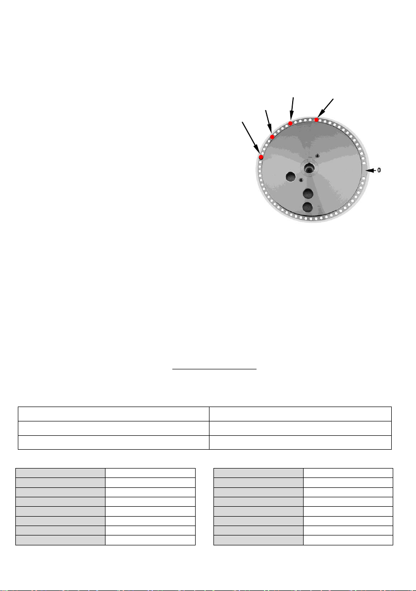
8 Use of the machine
8a Use of the standard machine
8a.1 General controls of the machine:
1. Protection for the bending area.
2. Regulation handle.
3. Emergency STOP button.
4. Supply light.
5. Return-reset button.
6. Remote control for pedal used by operator.
7. Speed selector (only PG 26 mono-phase)
8. Main inverter-switch.
9. Shear (only for combined machines).
10. Protection for the cutting area
(only for combined machines).
Machine plate
2
Machine plate
6
8a.2 Starting and working:
All the following operations must be executed maintaining the working plate free from any equipment
and without inserting any pin into the disc.
•Connect the supply cable as above described.
•Turn the main switch-inverter from the starting position 0 into position 1 or 2 according to the required
rotation direction. Push the reset button: now the light is on. In this way the bending disc does not
move in case it is already in the correct starting position. On the other hand, it moves to get
the correct starting position.
•Start the machine pushing the pedal to check the disc rotation direction. Stop the machine elevating
the foot from the pedal. Push the return button to place the disc in the starting position.
•The machine is ready to use the toolings.
•The reset operation has to be executed each time that:
- The machine stops because of the emergency-stop button.
- Voltage is untimely restored.
- A starting operation is executed through the main inverter-switch.
•To start the machine after an emergency STOP, it is necessary to unblock the button turning its
mushroom part and then to push the reset button; in this way the disc gets into the starting position,
ready for the following operations.
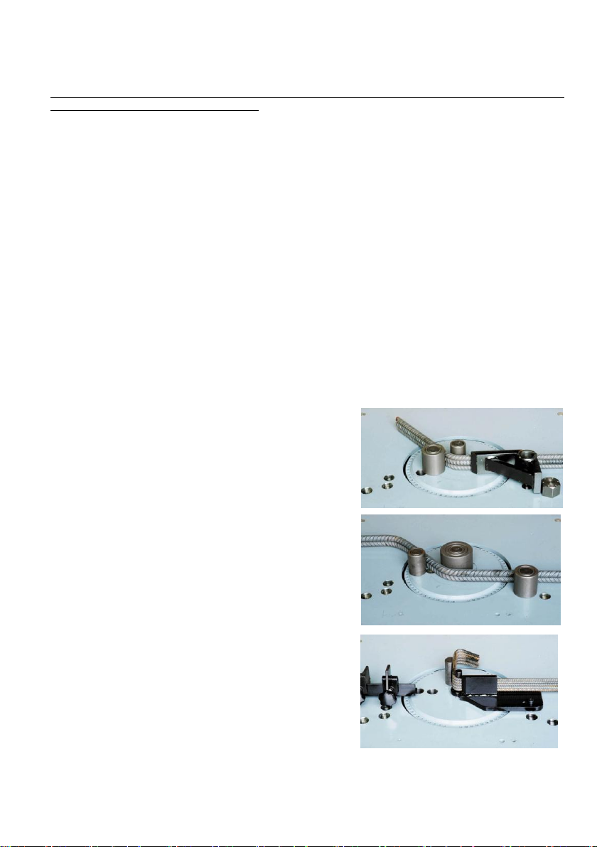
8a.3 How to bend a piece:
After all the above-described operations, prepare the toolings as follows:
a) Bending operation with square:
The picture shows the correct position of the equipment
ready for the bars bending using the square only for iron
with maximum diameter 14 mm.
The bending square allows to place the bar near the
bending centre, obtaining a perfect bending angle.
Placing the equipment in this way, the disc must turn
clockwise. Placing the equipment on the left side of the
working plate and turning the disc anticlockwise, it is
possible to obtain the same bending angles with the iron
coming from the left side.
b) Bending operation with pin and bush:
The picture shows the correct position of the equipment
ready for the bars bending using the pin with bush instead
of the square, allowing the bending of big diameters,
forcing less the machine and obtaining less sharp
bending angles. Thanks to this system, it is possible to
use bushes with a bigger diameter, as required by the
present legislation.
c) Stirrup bending with special tool:
(equipment on demand)
The picture shows the correct tooling for the stirrup
bending.
Three kinds of tools are at disposal:
- With central pin Ø20 for iron up to Ø10.
- With central pin Ø25 for iron up to Ø16.
- With central pin Ø30 for iron up to Ø20
7
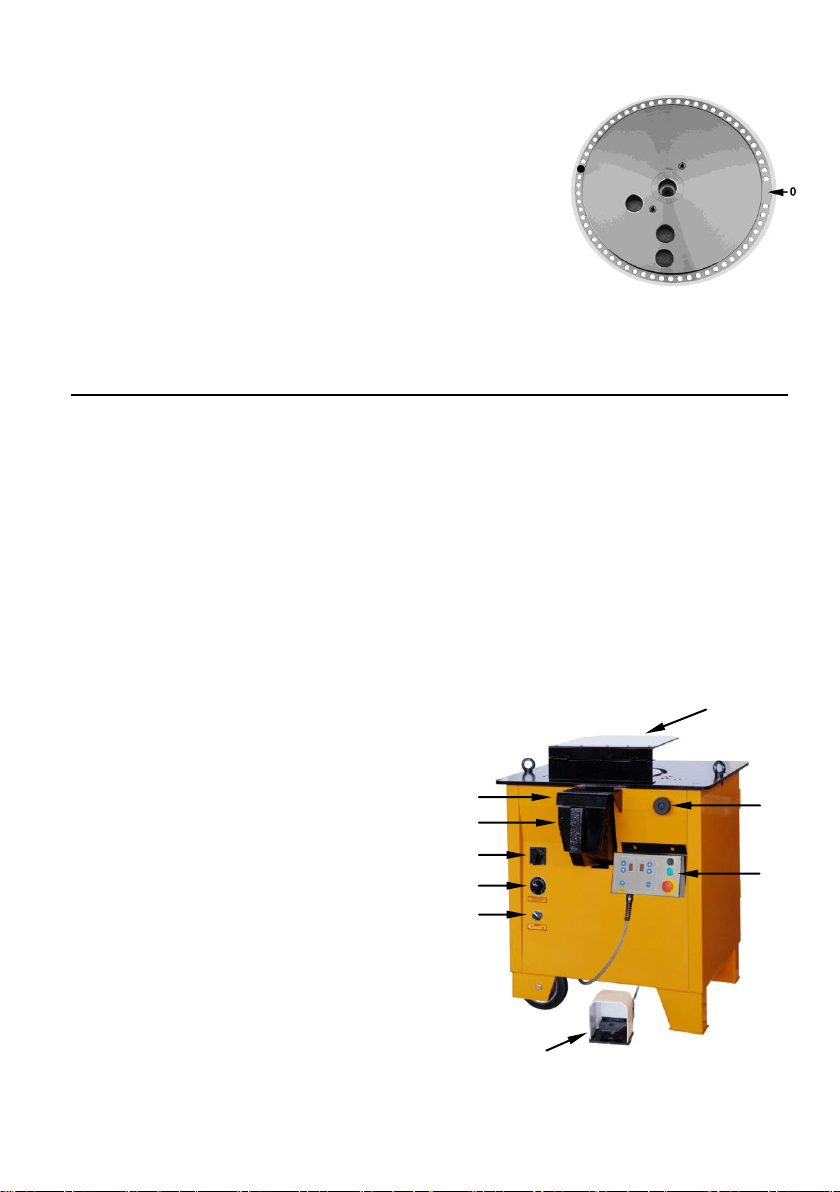
•Place the inversion pin into the disc holes to set the bending
angle. Considering position 0 as the limit-switch position, the
pin must be placed approximately according to the disc rotation
direction.
•The exact angle can be found after some bending tests, using
the regulation handle for some little angle corrections.
• After the pin insertion, place the iron bar to be bent on the working
plate and start the machine pushing the pedal; in this way the disc turns
and the bar is bent, until the pin touches the limit switch. When the
pedal is released, the disc turns back into the starting position.
•During the bending operation the pedal must always be pushed, since when it is released the machine
stops immediately.
•If the pedal is pushed during the return of the disc, it stops immediately in the position where it is.
8a.4 How to cut a piece (only for combined machines):
All the below-described operations must be executed with the working plate free of any kind of tooling.
•Connect the supply cable as above described.
•Turn the main inverter-switch from the starting position 0 into position 1 or 2.
•Insert a pin at 180° from the point 0.
•Push the reset button: now the light is on.
•When the machine is stopped and the disc is in the starting position, le blades are completely open.
Insert the bars to be bent into the space between the blades under the shear protection, and put
them at the required length. Execute the cutting operation through the remotely-controlled pedal,
keeping it pressed till the end of the cutting operation and automatic disc return –which is settled
according to the pin position.
Repeat the same operation for each cutting execution.
8b Use of the machines with the panel 9x9 and the speed variator:
•The panel was designed to allow the operator to execute a bending sequence without stopping and
move the pin. In this way, a lot of time on the production can be saved.
•The speed variator allows the operator to choose the number of bending-disc turns.
8b.1 General controls of the machine:
1. Protection for the bending area.
2. Regulation handle.
3. Movable panel 9x9.
4. Remote control for pedal used by operator.
5. Panel selector ON-OFF.
6. Speed-variator.
7. Main inverter-switch.
8. Shear (only for combined machines).
9. Protection for the cutting area
(only for combined machines).
2
3
1
4
5
6
7
8
9

8
Panel controls:
10.Bending indicator (maximum 9).
11.Pin n° indicator (maximum 9).
12.Pin buttons.
13.Return button.
14.Starting button (including the light).
15.Emergency-stop button.
16.Reset button.
17.Program-light on.
18.Button for programme activation-deactivation.
19.Bending buttons.
8b.2 Starting and working:
All the following operations must be executed maintaining the working plate free from any equipment
and without inserting any pin into the disc.
•Connect the supply cable as above described.
•Turn the main switch-inverter from the starting position 0 into position 1 or 2 according to the required
rotation direction. Push the reset button: now the light is on. In this way the bending disc does not
move in case it is already in the correct starting position. On the other hand, it moves to get
the correct starting position.
•Start the machine pushing the pedal to check the disc rotation direction. Stop the machine elevating
the foot from the pedal. Push the return button to place the disc in the starting position.
•The machine is ready to use the toolings.
•The reset operation has to be executed each time that:
- The machine stops because of the emergency-stop button.
- Voltage is untimely restored.
- A starting operation is executed through the main inverter-switch.
•To start the machine after an emergency STOP, it is necessary to unblock the button turning its
mushroom part and then to push the reset button; in this way the disc gets into the starting position,
ready for the following operations.
•The machine can be used with the panel controls if, the panel-selector ON-OFF is placed into
position ON.
•The machine can be used in the manual way, excluding the panel, if the panel-selector ON-OFF is
placed into position OFF. In this position anyway the controls return, reset and emergency-stop on the
panel are still active.
8b.3 Working for the bending operations:
The toolings placing is the same as described at point 8a.3.
8b.4 Working for the cutting operations (only for combined machines):
The cutting execution is the same as described at point 8a.4: remember to move the panel in order
not to touch the bars to be cut.
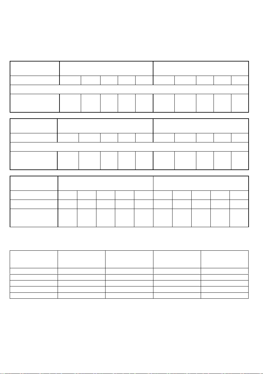
8b.5 Example of panel-programming for a shaped piece with 5 bendings and 4 different angles:
1° bending = 135°
2° bending = 90°
3° bending = 120°
4° bending = 60°
5° bending = 135°
1
2
3
4
5
10
11
12
13
14
15
16
17
18
19
60°
90°
9
Place and number the pins as follows:
The pins are 4, corresponding to the 4 different angles (make some tests to find out the correct position).
Place as in the picture, considering that the rotation direction is clockwise:
The pin at 60° is n° 1 (the numbering starts with the one nearest the limit switch).
The pin at 90° is n° 2
The pin at 120° is n° 3
The pin at 135° is n° 4
Panel-programming for the
bending sequence:
a) Push the button for programme activation-
deactivation: the light is on and the
programme is active.
b) Using the bending buttons select 1 (1° bending)
and using the pin buttons select 4
(n° of the pin corresponding to the 1° bending).
c) Repeat the operations for the following
bendings:
•Bending 2 pin 2
•Bending 3 pin 3
•Bending 4 pin 1
•Bending 5 pin 4
d) The programme ends when the 6° bending is selected on 0.
e) Push the button for programme activation-deactivation: the light is off and the programme is not
active.
f ) Keep the RESET button pressed for 4÷5 sec. and start the programme with the 1° bending.
Bending repetition
a) Push the button for programme activation-deactivation (light on).
b) Using the bending buttons select the required bending.
c) Push the button for programme activation-deactivation (light off).
d) Push the pedal to execute the chosen bending. The programme goes on with the next bending.
Push RESET for 4÷5 seconds to start the programme with the 1° bending.
9 Limitations on the use
9.1 European legislation UNI EN 1992-1-1 Chapter 8 - paragraph 8.3
Minimum diameter of the mandrel to avoid damages to the concrete:
Bar diameter
Minimum diameter of the mandrel
Ø ≤ 16MM
4 x Ø bar
Ø > 16MM
7 x Ø bar
Mandrel table
Ø bar
Ø mandrel
Ø bar
Ø mandrel
Ø 6
Ø 24
Ø 20
Ø 140
Ø 8
Ø 32
Ø 22
Ø 154
Ø 10
Ø 40
Ø 24
Ø 168
Ø 12
Ø 48
Ø 26
Ø 182
Ø 14
Ø 56
Ø 28
Ø 196
Ø 16
Ø 64
Ø 30
Ø 210
Ø 18
Ø 126
Ø 32
Ø 224
120°
135°
10
9.2 Maximum working performance:
The maximum working performance is represented by the possibility of bending together one or more
bars, according to the diameter and strength of the rod.
Mandrels indicated in the following tables show maximum performances of the machine not keeping in
consideration the iron yield point. For constructions made in reinforced concrete it is necessary to use
the mandrels complying with Laws in force.
Type
PG 26 three-phase
PG 30 three-phase
n°bars
1
2
3
4
5
1
2
3
4
5
Ø mandrel
100
69
69
55
48
130
100
69
55
48
650 N/mm²
22
16
14
12
10
26
18
14
12
10
850 N/mm²
20
14
12
10
10
22
16
12
10
10
Type
PG 35 three-phase
PG 40 three-phase
n°bars
1
2
3
4
5
1
2
3
4
5
Ø mandrel
130
100
69
55
48
130
130
87
68
68
650 N/mm²
30
22
18
14
10
34
24
18
16
14
850 N/mm²
26
20
16
14
10
30
22
16
14
12
Type
PGT 32/25 three-phase
Bending
PGT 32/25 three-phase
Cutting
n°bars
1
2
3
4
5
1
2
3
4
5
Ø mandrel
130
100
69
36
36
650 N/mm²
26
18
14
12
10
22
16
12
10
10
850 N/mm²
22
16
12
10
10
20
14
10
10
10
Maximum working performance for mono-phase machines:
The supply value (VOLT) must be checked during the working process.
Machine type
Operation
Maximum
performance at
220V
Maximum
performance at
200V
Maximum
performance at
190V
PG 26 –8 turns
Bending
Ø22 (mandr. Ø100)
Ø20
Ø18
PG 26 –12 turns
Bending
Ø18 (mandr. Ø100)
Ø16
Ø14
PG 30
Bending
Ø24
Ø22
Ø20
PGT 32/25
Bending
Ø24
Ø22
Ø20
PGT 32/25
Cutting
Ø20
Ø18
Ø16
Supply cable for mono-phase machines:
An inappropriate supply cable can cause a voltage drop decreasing the machine performance.
Supply cable section:
2,5 mm² for a cable with maximum length 15 meters
4 mm² for a cable with maximum length 60 meters
6 mm² for a cable with maximum length 80 meters

11
10 Malfunctioning, failure and breakdown
Following, the most common malfunctioning situations on the machines:
a) The machine cannot bend the maximum diameters as in the schedules:
•Check if the line voltage is over the tolerance 5%.
•Check if the diameter of the cable used to supply the machine is long enough to avoid any current
leakage.
•Check the transmission belting stretching and efficiency: they could split during the maximum effort of
the machine.
•Check if the bars strongness corresponds to the foreseen parameters according to the use limitations.
•Check the blades efficiency (only for combined machines). In case the blades are damaged, also just
in part, the machine can not cut the maximum diameter on the schedule.
b) The machine stopped and it doesn’t start again:
•Check if the emergency buttons are not pushed.
•Check the position of the bending protection and its limit-switch.
•Check the position of the cutting protection and its limit-switch
•Check if the current reaches the electrical box.
•Check the pedal components.
c) The disc turns without stopping at the limit-switch signal:
•Check that the pin position is perfectly in the required hole.
•Check the two limit-switches: they could be damaged or simply moved.
11 Maintenance, inspections and checks
Our advice is to submit periodically the following checking:
11.1 Oil level:
Monthly check the oil level and add it in case the level is too low.
The complete oil substitution is recommended each 4.000 working hours, unloading all the spent oil in
the reducer unscrewing the unload cap. After the unload-cap cleaning, screw it and full the reducer
pouring the oil through the load cap in the quantity required by the indicated level using oil type CC
460 ( ISO E UNI ) or some correspondents:
Mobil
MOBILGEAR
634
Shell
OMALA OIL
460
Agip
BLASIA
460
Esso
SPARTAN
EP 460
Castrol
ALPHA
SP460
BP
ENERGOL
GR-XP 460
11.2 Belts:
Check tension and conditions of the driving belts.
The belts have to be always well tightened to avoid any slipping that might lead to a malfunction or a
quick wear of the belts themselves.
11.3 Blades replacing:
Check every 40 working hours the blades efficiency and replace them in case they are damaged.
For the blades replacement it is enough to unscrew the blades from the machine. For the unscrewing
of the mobile blade from the rod, the blade must stop totally outside the machine. To obtain this,
follow these instructions:
a) Check that there are no pins into the bending disc and that the machine working plate is empty from
all the fittings.
b) Turn the machine on, turning the main inverter-switch.
c) Push the reset button.
d) Push the pedal for the mobile blade exit and release it when the blade is completely outside.
e) Detach the machine tension.
f ) Replace the mobile blade.

12
12 Cleaning
In case of cleaning do not use any solvents which could damage the machine.
Clean and lubricate carefully all the holes and the sliding parts.
13 Machine keeping
•In case the machine does not work for a long time, it is better to grease or lubricate the unpainted
parts of the machine.
•Moreover, grease or lubricate all the pins, the bending bushes and the toolings.
•Unplug the power cable.
•If the machine is placed outdoors, cover it completely with waterproof material.
•The standard life of the machine used according to the instructions of this handbook and to a correct
periodical maintenance is about 20.000/30.000 working hours.
14 Demolition and disposal
There is no particular caution before breaking up the machine, because it does not contain dangerous
materials. In case of breaking up, it is necessary to separate three different materials: oil contained in
the reduction gear, copper of the motor/electric system and metal parts.
15 Safety instructions
a) It is forbidden to repair, set, service or clean any moving part.
b) The safety guards and devices in the machine must not be removed or modified.
c) Dimensions and shapes to be bent or cut cannot be foreseen and, for this reason, the worker must
produce some supports if necessary to avoid any danger for the worker himself.
16 Safety devices
The machine is provided with the following safety devices:
16.1 Magneto-thermic switch and differential.
16.2 Grounding of the machine-body.
16.3 Button for emergency-stop:
The machine is equipped with a mushroom-button as emergency-stop. Through this control the
machine power is immediately off.
16.4 Controls for machine starting:
All the controls are produced with purpose protections according to their use in order to grant a
protection IP 54, according to the EC legislation, and they cannot start accidentally.
16.5 Man-driven control foot-pedal:
The machine starting control is given by the man-driven electrical foot-pedal: the bending operation
starts only if the pedal is kept pushed.
Whenever the pedal is released, the machine stops immediately.
16.6 Guards for gear parts:
The gear parts are arranged in the machine frame and they are protected by a screwed-on door which
can be opened only by means of a wrench: in this way the contact is impossible.
The removal of this door is allowed for maintenance purposes only and therefore the power supply
must be disconnected.

13
16.7 Moving interlocking guards for bending area:
The guard for the moving parts is a hinged sheet metal plate that can be opened. It is a moving guard
provided with a safety electrical contact - called tampering prevention interlock –which stops
immediately the machine in case it is open even partially; the machine cannot start since the guard is
completely closed.
16.8 Fixed guard for cutting area:
The cutting area is guarded by a fixed steel protection.
17 One-man safety devices
The use of protection gloves and safety shoes is compulsory as safety devices for the worker.
18 Residual risks
1) Mechanical risks: In the bending area the residual risk consists in the possible impact of hands
against the guard.
The cutting area presents the risk of shearing for the upper limbs.
The two protections shows a warning signal.
2) Electrical risk: The machine is supplied with 400 V and it gives an electrical residual risk.
3) Noisiness: The level of the equivalent continuous sound pressure ponderate A of the
machine results less than 70 dB during the bending and cutting operation.
19 After-sales service during guarantee
1) The machines have a guarantee of 24 months from the date of delivery, and the guarantee is
valid only if the GUARANTEE CERTIFICATE (sheet enclosed) has been duly filled in and sent
to TECMOR company. OTHERWISE THE MACHINE WILL NOT BE COVERED BY GUARANTEE.
2) The producer undertakes to repair any manufacturing defect found during the period of guarantee.
That means the free replacement of the faulty parts after the producer has made sure of the
manufacturing or material defects.
3) The user shall send the producer the faulty part - covered by guarantee - to make it repaired. The cost
and the risk of the transport of the faulty or repaired / replaced parts are borne by the user.
4) If the repair of the replacement must take place where the machine is installed, the travel, board and
lodging expenses for the producer’s technicians will be invoiced to the user. The replaced parts will
not be charged.
5) This guarantee does not cover the parts subject to a particular wear or wrongly used, not maintained,
overloaded or modified.
6) The after-sales service during the period of guarantee will be carried out promptly; however TECMOR
company will not answer for any possible delay.
20 Spare-parts
A complete catalogue of the spare parts is supplied at customer’s request or is available at the area
dealer. According to the EC legislation, TECMOR grants delivery and availability of spare-parts for
maximum ten years after the date of purchase.
This manual suits for next models
7
Table of contents
Popular Cutter manuals by other brands


Z.I.P.P.ER MASCHINEN
Z.I.P.P.ER MASCHINEN ZI-MOS4TA user manual

Blue Diamond
Blue Diamond Multi-Purpose Cutter Operation and parts manual

US Cutter
US Cutter Copam user guide

CustomCrimp
CustomCrimp CC38 Operator's manual

parktool
parktool CN-10 instructions

Central Pneumatic
Central Pneumatic 47077 Assembly and operating instructions