NovaTec NovaWheel NWB- DC+ Series User manual
USER GUIDE
MODELS:
NWB- DC+ Series, With NovaTouch™
7” Color Touch Panel PLC
> MODELS NWB-25-DC+ through
NWB-300-DC+
NWB-DC Series, With NovaTouch™
4” Color Touch Panel PLC
> MODELS NWB-25-DC through
NWB-200-DC
NovaWheel™Portable
Dry-Convey Dryers
NWB-DC & DC+ UG 18 JULY 2019
©2019 NOVATEC, Inc. All Rights Reserved

In the space provided below you should record the model and serial
number(s) of your equipment and the date the equipment was received.
In the event you would need aermarket assistance our parts and ser-
vice department uses this informaon, along with the manual number, to
provide help for the specic equipment installed.
Please keep this instrucon manual, any relevant addendums, engineer-
ing prints and parts lists together for accurate documentaon of your
equipment.
NOTES
User Manual: NWB-DC & DC+ UG 18 JULY 2019
Serial Number(s):
Model Numbers:
DISCLAIMER: NOVATEC, Inc., shall not be liable for errors in this instrucon
manual. Informaon can change without noce. Novatec makes no warranty of
any kind concerning the informaon contained herein, including, but not limited
to the implied warranes of merchantability and tness for a parcular purpose.
©2019 NOVATEC, Inc. All Rights Reserved.

Table of Contents
1.0 SALES AND SERVICE 6
2.0 SHIPPING AND INSPECTION 6
3.0 UNPACKING for NovaWheel™
NWB-DC & DC+ DRY/CONVEY MODELS 6
3.1 Unpacking 6
3.1.1 Tools You Will Need for Unpacking: 6
3.1.2UnpackingInstrucons: 6
3.1.3 List of UNPACKED CONTENTS: 6
4.0 BASIC COMPONENTS OF NOVATEC
NWB-DC DRYER ASSEMBLY 7
4.1DierencesinLayoutfor-300model 8
5.0ASSEMBLYINSTRUCTIONS 8
5.1Prepare/AssembleMachineMountReceiver 8
5.2 Mount Hopper Receiver & Connect
FlexHoseandPickupWand 8
5.3PosioningtheNWB-DC 9
5.4 Install Machine Mount Receiver and
ConnectFlexHose 9
6.0 ELECTRICAL CONNECTIONS 10
7.0 PRE-COOLER WATER CONNECTIONS 11
8.0COMPRESSEDAIRCONNECTION 11
9.0HOPPEREXTENSIONS 11
10.0 ADJUSTABLE DIFFUSER CONE POSITIONING 11
11.0 PRINCIPLE OF OPERATION 11
11.1ResinDrying 11
11.2ResinConveying 12
11.3SystemFlowDiagram 12
12.0 SPECIFICATIONS – NWB-DC+ DRY CONVEY SERIES 12
13.0 FUNCTION CONTROLS 13

4
13.1ProcessTemperatureControl
(DryingTemperature) 13
13.2RegeneraonTemperatureControl 13
13.3Process&RegeneraonAirFilter
PressureSwitches(PS) 13
13.4ProcessAirDewPointMonitor 13
13.5IntelligentRegeneraon 13
13.6ConveyingControl 13
14.0 PRE-OPERATING SYSTEM CHECK 13
14.1StarngTheDryer 13
14.2 Checking Electrical Phase 13
14.3ChangingFromF°toC° 13
15.0 NovaTouch™ CONTROL 14
15.1SystemConvenons: 14
15.2 Screen Map 15
16.0 INITIAL DRYER STARTUP 15
16.1DryerPre-Check 15
16.2ExplanaonofPasswordLevels 15
16.3 WELCOME Screen 16
PressingMETRICwillchange°Fto°C. 16
16.4Verify/SetTime&Date 16
16.5AutoStart/Stop(Level2) 16
16.6MaintenanceSchedule(setup) 17
16.7InstallaonChecklist(setup) 17
17.0SETTINGSSCREEN(Anylevelcanview) 18
17.1DryerAlarmSengs(level2) 18
17.2UsersManagement 19
17.3AdvancedOpons(level2&up) 19
17.4TouchScreenSengs 20

5
18.0DRYINGMATERIAL 20
18.1QuickOpScreen 20
18.2HopperLoaderSetup 21
18.3MachineLoaderSetup 22
18.4ResinMenu 22
18.5DryerStatusScreen 23
18.6MessageScreen–Alarms 23
19.0INSTRUCTIONALTROUBLESHOOTINGSCREENS 23
20.0 MAINTENANCE INSTRUCTIONS 25
20.1 Suggested Maintenance Schedule* 25
20.2 Filters 25
20.3ProcessandRegeneraonFilters 26
20.4ConveyingAirFilter 26
20.5DrainingPlascizer 26
20.6 Chain and Sprockets 26
20.7 Desiccant Rotor 26
20.8MotorRotaonSignal 26
20.9RotorReplacement 27
20.10SealReplacement 27
20.11DriveMotorReplacement 27
21.0TROUBLESHOOTINGandERRORMESSAGES 28
22.0WARRANTY 29
FOREWORD
Thismanualisdedicatedtotheprinciplethatanyengineeredsystemwillhave
manyelementscontribungtothesmoothoperaonofthesystem,andthat
thesemustbeunderstoodinorderthatinstallaonandoperaoncanproceed
successfully.
TheelectricalandmechanicalcomponentsintheNWB-DCSeriesdryershave
beenmanufactured,selectedandassembledwithcaretogiveyouexcellent
service.AwiderangeofNWB-DCseriesdryershavebeenintroducedtoenable
ourvaluedcustomerstoselecttherightmodelfortheirapplicaon.TheseNWB-
DC(NovaWheel™Dry/Convey)seriesdryershavebeendesignedforbeside-the-
pressdryingapplicaons.AllcomponentsofyourNWB-DCseriesdryershave
beencarefullyengineeredandmanufacturedandhavebeenthoroughlyinspect-
edforquality,funconandperformance.
Beforeinstallingthissystem,pleasereadthismanual,reviewthediagramsand
thesafetyinformaon.Thisshouldsavevaluableinstallaonandoperaonme
laterandwillhelpensuresafeoperaonandlonglife.

6
Figure 2
1.0 SALES AND SERVICE
NOVATECmaintainsqualiedsales,engineering,and
servicepersonneltoassistinanywaypossible.Ifyou
haveanycommentsconcerningthetypesofequipment
whichNOVATECmanufacturesthatmightimproveyour
process,oranyquesonsconcerningservice,weurge
youtocontactus.PleasehaveyouModelandSerial
Numberhandy.
Sales:1-800-BEST-DRY●1-800-237-8379
Fax:410-789-4638●[email protected]om
TechnicalServiceDepartment:1-800-938-6682
Service@novatec.com
2.0 SHIPPING AND INSPECTION
Although NOVATEC uses reputed carriers to deliver
products,ithasnocontrolovertheproductsonceit
leavesthemanufacturingfacility.Uponreceivingthe
products,thoroughlyinspectallequipmentinsideandout
fordamagethatmayhaveoccurredduringshipment.If
anydamageisfound,aclaimshouldbeledimmediately
withyourcarrier.
NOVATECthoroughlytestsandinspectsallproducts
beforeshipment.Youaretomakethepiping,andelectri-
calconneconsfornalinstallaonandcommissioning.
Ifthereanyproblems,shutdowntheequipmentand
contacttheNOVATECTechnicalServiceDepartment.
3.0 UNPACKING for NovaWheel™ NWB-DC &
DC+ DRY/CONVEY MODELS
3.1 Unpacking
3.1.1 Tools You Will Need for Unpacking:
•BoxCuer
•Malletorhammer
• Tin Snips
•½”socketwrenchfor-150through-300modelonly
1–Pleaselookforanysignsofdamageandreportto
yourcarrierimmediately.
2–UnpacktheDryer/Hopper
3–Removeshrinkwrap,andanywoodframing
aachedtotheskid.
4–CutthemetalstrappingthatsecurestheDryer/
Hopper to the skid.
5–LitheDryer/Hopperothepalletandsetitina
low-tracarea.
NOTE:Allmodelsareshippedwithcastersinstalledex-
ceptthe-150&-200,sowhiletheyarebeingsupported
bytheforkli,aachoneofthesuppliedcastersunder
eachcorneroftheframeusinga½”socketwrench.
–Unpackthecomponentstobeassembledfromseparate
cartons.
–Removetheshrinkwrapfromthecarton(s)andtakeout
the contents.
NOTE:TheHopperReceivershouldbesetontheoor
withtheboominsidetheroundbertube(supplied)so
theboomapperisprotectedbythetube.
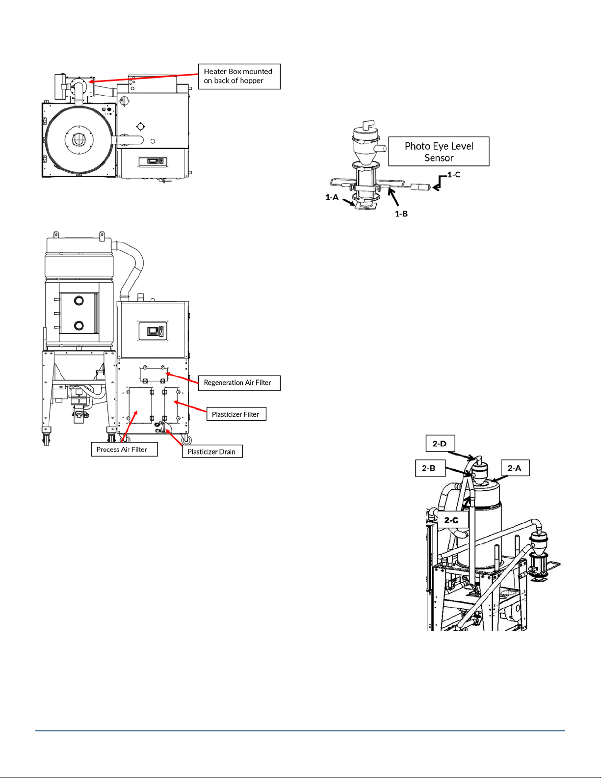
3.1.3 List of UNPACKED CONTENTS:
•Dryer/HopperAssembly
•MachineMountReceiver(withsightglass)
•HopperReceiveronFiberTube(withappervalve
underneath)
• 5’ Long Pickup Wand
•PhotoEyeLevelSensor
• 50’ of 1.5”of Flex Hose*
•8HoseClamps
•Casters,Bolts&Washers(packedseparatelyfor
-150 & -200
7
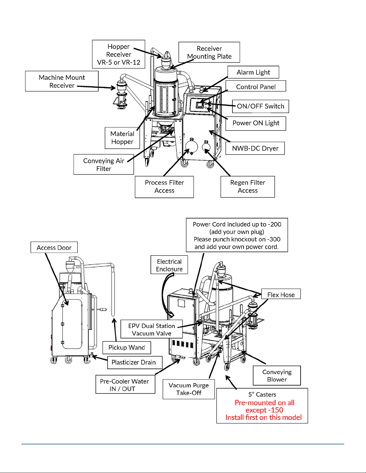
4.0 BASIC COMPONENTS OF NOVATEC
NWB-DC DRYER ASSEMBLY
8
5.0 ASSEMBLY INSTRUCTIONS
ToolsYouWillNeedforAssembly:
•HacksawtocutPVCexhose
•FlatBladeScrewdriverand/or5/16”socketforhose
clamps
•5/32”AllenwrenchtomountReceivers
•Drillpressanddrillbitsizedtomatchmounngholes
onmachinethroatsoholescanbedrilledinbaseof
MachineMountReceiver.(Unlessbaseispre-drilled)
•6’-8’Ladder
•Tapemeasure
NOTE:Asyouproceedwithassembly,makesurethatall
boltsandhoseclampsaresecurelyfastenedtoensure
thattherearenoairormaterialleaksinthesystem.Do
notuseexcessiveexhosebutavoidsharpturnsasthis
willhurttheeciencyofthesystemoperaon.
5.2 Mount Hopper Receiver & Connect Flex Hose and
Pickup Wand
2-A: RemovecoverplatefromtopofMaterialHopper
(saveboltsandwashers)then,aerremovingmask-
ingtapefromapper,placeHopperReceiverin
hole.Aligninletstubtofacedireconfromwhere
materialwillbepulled.FastentheReceivertothe
Hopperusingthesaved¼”x20boltsandwashers.
2-B: Placehoseclampoveroneendofexhoseand
pushendofthehoseontothematerialinletstub
onthesideofthereceiver.Fastenhoseclamp
securely.
2-C: Cuttheexhosetoalengththatwillallowthe5’
longpickupwandtoreachallcornersofthebulk
container
supplyingthe
materialtothe
dryerhopper.
Push the cut
end of the
exhoseover
the end of the
pickupwand
and secure
withhose
clamp.
2-D: Followsame
instrucons
toaachex
hose running
fromthevacu-
umstubontopoftheHopperReceiverto the near-
(Seeillustraon)
9
Hopper Receivers with Blowbackaresuppliedwitha
male/femaletwistlockplugtowhich115/1/50-60VAC
shouldbewired.Acleansourceof80-120psicom-
pressedairshouldbeconnectedtothesuppliedFNPT
ng.(3/8”ontheVR-5and¼”ontheVR-12)
RolltheNWB-DCintoposionnexttotheprocessma-
chineitwillbeserving.
NOTE: LOCATION
PosionyourNWB-DCSeriesdryerinalocaonwhere
materialandvacuumhoseswillnotbedisturbed.Allow
sucientdistance(atleast2feet)fromthesurround-
ingequipment,sotheaccessdoorsmaybeopenedto
performrounemaintenanceonthedryerandforsafe
operaon.
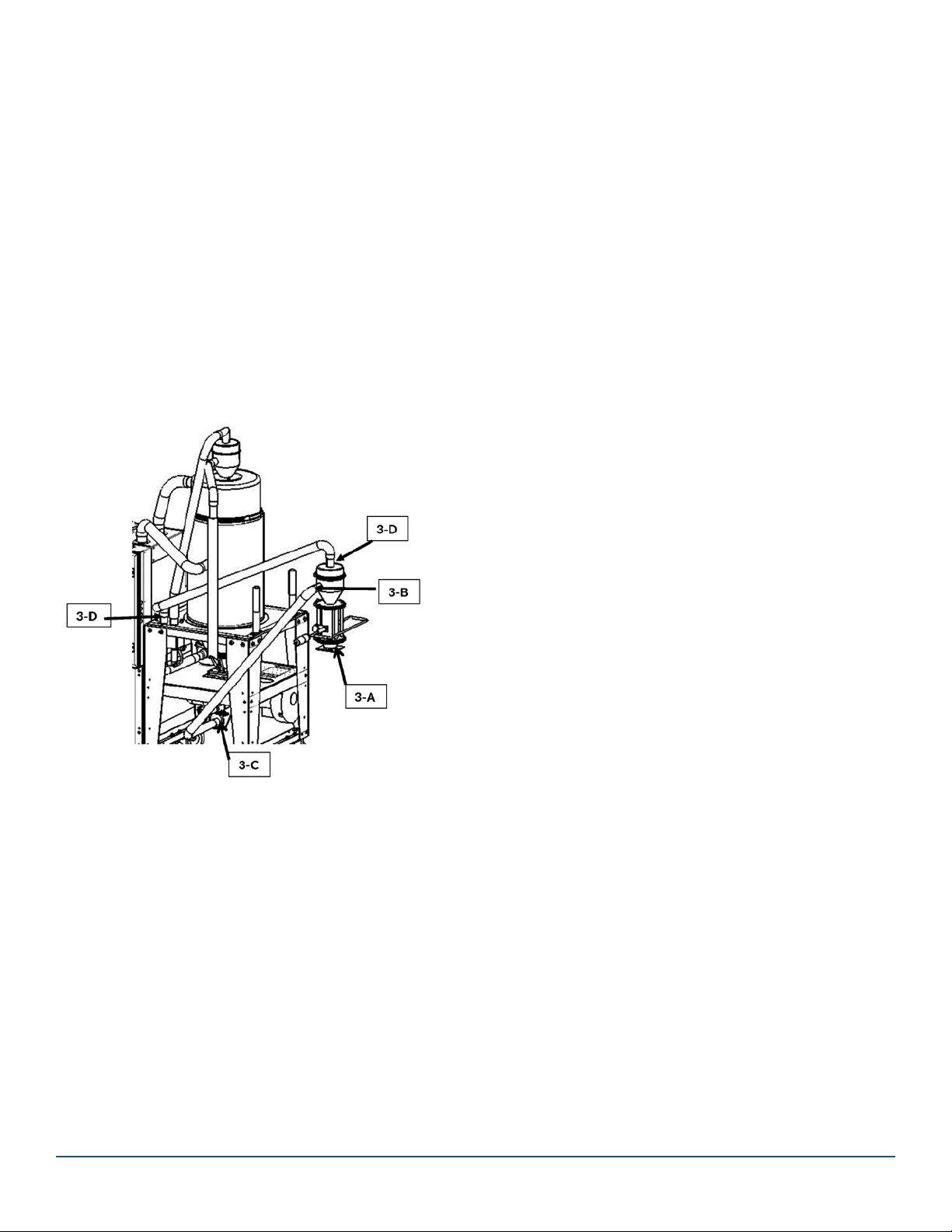
5.4 Install Machine Mount Receiver and
Connect Flex Hose
5.4 Install Machine Mount Receiver and Connect
Flex Hose
3-A Bolt the Machine Mount Receiver to the process
machinethroatwithuser-suppliedbolts.
3-B Pushoneendoftheexhoseallthewayontothe
materialinletstubonthesideofthereceiverand
fastenitsecurelywithahoseclamp(supplied).
3-C Stringexhosetothevacuumpurgetake-o(at-
tachedtotheboomofthehopper)cutittolength
andfastensecurelywithahoseclamp.
3-D Aachoneendofexhosetothevacuuminletstub
on top of the Machine Mount receiver and fasten it
securelywithahoseclamp.Stringtheexhoseto
thefarthestEPVDualStaonVacuumValveStub
extendingfromthetopofthedryer.Cutexhoseto
lengthandaachitsecurelytothestubwithahose
clamp.

10
6.0 ELECTRICAL CONNECTIONS
TheNWB-DC+Seriesdryerscomefromthefactory
withallcontrolcircuitswiredanda10’powercord.
Aquick-connectplugshouldbeinstalledifmoving
theNWB-DC+tootherprocessmachinesisanci-
pated.
CAUTION
•Allelectricalconneconsmustbemadebyqualied
electricians,pernaonalandlocalelectricalcodes.
•Disconnectandlockoutthemainpowersourcebefore
makingtheelectricalconnecon.
Turn the Main Disconnect on the electrical panel door to
the“OFF”posion,lockoutthemainpowersourceand
opentheelectricalenclosure.Pertheelectricaldiagram,
installthemainpowerwiretothemaindisconnectswitch
holderandinstallthegroundwire.
Full size electrical drawings are included with this
ordered
NOTE: 3 Phase detecon is included on this model. If
the connecon is not correct, a pop-up alarm will appear
on the touch screen upon startup. You should immediate-
ly correct this condion.
NOTE: Please make sure all electrical connecons are
ght. It is not common but a loose connecon is possible
aer a long truck ride.
Model Total connected
power KVA/AMPS
Pro Motor
Hp/AMPS
Regular Motor
Hp/AMPS
Regular Heater
Kw/AMPS
Pro Heater
Kw/AMPS
-25 9.0/10.8 .025/0.4 .025/0.4 3.0/3.8 3.0/3.8
-50 11.9/14.7 0.67/1.2 .025/0.4 3.0/3.8 5.5/6.9
-75 14.2/17.8 1.1/1.8 .025/0.4 3.0/3.8 7.5/9.4
-100 16.7/20.9 1.1/1.8 .025/0.4 5.5/6.9 7.5/9.4
-150 16.7/20.9 1.1/1.8 .025/0.4 5.5/6.9 7.5/9.4
-200 24.0/30.1 2.5/3.5 0.67/1.3 5.5/6.9 13.0/16.3
-300 38.3/48.0 3.5/5.4 0.67/1.3 10.0/12.6 22.5/28.2
11
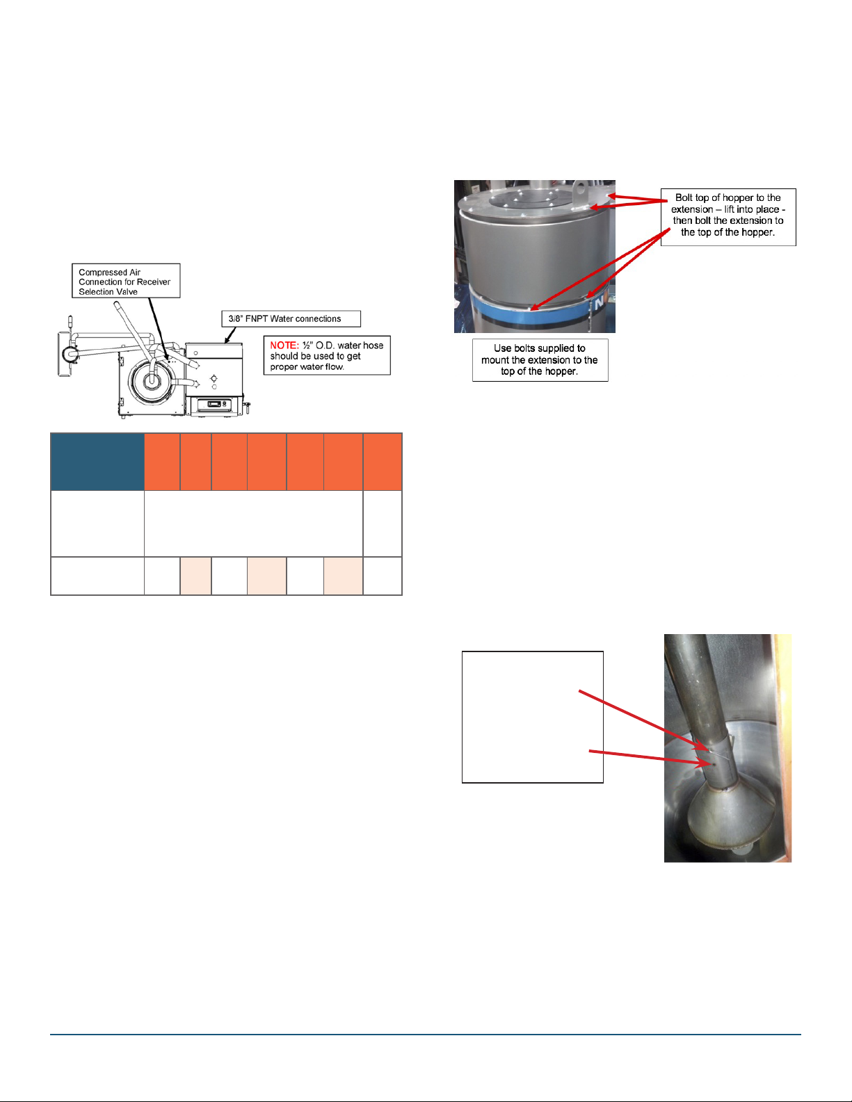
7.0 PRE-COOLER WATER CONNECTIONS
ACoolingCoilisinstalledinNWB-DC+seriesdryersand
isrequiredtolowerthehopperreturntemperatureand
thisincreasestheeciencyofdryerIF THE DRYING
TEMPERATURE IS ABOVE 225°F .
Tower,cityorchilledwaterisrequiredatbetween40to
85°F.Connectthecoolingwatersupplyandreturnusing
exiblehosethatisatleast2feetlong,toallowforeasy
removalofthecoolingcoilforcleaning.Thewaterow
ratesandtherequiredcustomerconneconsizesfor
dierentmodelsareshowninthechartbelow.
NOTE: Processor must use ½” ID water hose to get
properow.
NOTE: Cooling water is required if drying temperature is
over 225°F.
Theprocessairstreammustbeconnectedtoanexternal
coolingcoilifthedryingtemperatureisbelow170°F.
ContactFactoryforOpons.
8.0 COMPRESSED AIR CONNECTION
Thetouchscreencontroloperatesadualstaonvacuum
valveinsidethedryertoacvatevacuumtoeitherthe
hopperreceiverorthemachinemountreceiver.Aclean
compressedairsupply(60-90psi)shouldbeconnectedto
the1/8”NPTinlet.
9.0 HOPPER EXTENSIONS
Ifyouorderedahopperextension,itwillbeabolt-on
type.Theextensionwillbeinstalledatthefactoryifthe
overallheightoftheunittsintoastandardheighttruck
forshipping.Iftheunitistootallfortheextensiontobe
factory-mounted,itwillbeshippedinaseparatecontain-
erandmustbeinstalledattheprocessor’splant.
10.0 ADJUSTABLE DIFFUSER CONE
POSITIONING IMPORTANT FOR
PROPER DRYING
Wehavefoundthatprocessorscanimprovetheecien-
cyoftheirdryingprocessbyadjusngtheposionofthe
diuserconeasdescribedbelow.
Thediuserconeshouldbeplacedinthelowerposion
z(shown)whendryingvirginresinorresinwithalow
percentage of regrind.
Whendryingresinwithahighpercentageofregrind,
spreadtheclip,raisetheconeandplacetheclipthrough
thelowersetofholes.
Clip through upper
setofholesforlow
percentage of regrind.
Clip through upper
set of holes for higher
percentage of regrind
To raise level of cone.
YouarenowreadytoproceedtoDryerSetup.
SeeQuickCardaachedtodryer.
Models
NWB-XX-DC
NWB-XX-DC+
.25 -50 -75 -100 -150 -200 -300
Water
Inlet/Oulet
(inches)
3/8 1/2
Flow Rate-
0.25 0.5 0.75 1.0 1.5 3.0 3.0

12
11.0 PRINCIPLE OF OPERATION
TheNWB-DC+Seriesisdesignedtoconveymoisture
ladenresinfromasourcecontainer,dryit,anddeliverit
tothethroatofaprocessmachine.
TheNWB-DCandDC+NovaWheelSeriesdryerswas
engineeredanddesignedtoeecvelyremovemoisture
(inthevaporstate)fromhygroscopicplascresins.This
processisaccomplishedbytheconnuouslyrotang
desiccantwheelandthethreeairstreams(Process,Purge
andRegeneraon).TheProcessreturnairisexposed
toanadsorbingmedia(desiccantwheel)inasealedair
stream,wherethedesiccantadsorbsthemoisturefrom
processair.Aerthedesiccanthasadsorbedthemois-
ture,itisexposedtoaRegeneraonairstreamwhich
hasbeenpre-heatedtoatemperatureofabout380°F.
(190°C).Thiscausesthemoisturetobedrivenoutfrom
thedesiccantandpreparesitformoremoistureadsorp-
on.Nowthedesiccantmediapassesthroughthirdair
streamcalledpurgeairstream.Herethedesiccantmedia
iscooleddownbysomeoftheprocessairbeforeen-
teringbackintotheprocesstoprovideforbeerper-
formance.Thethreeairstreams(process,regeneraon
andpurge)areseparatedbyspecialTeonfabriccoated
siliconseals.Theprocessairandregeneraonairiscom-
pressedbyusingregeneraveblowers.
Thedryairfromthedryeristhenheatedtothedesired
dryingtemperaturebyanelectricheaterlocatedinthe
dryercabinet.Thehotdryairentersthehopperatthe
boomandremovesmoisturevaporfromtheresininthe
hopper.Theairfromthetopofthehopperisreturned
tothedryer,whereitisltered,passedthroughthe
desiccantwheeltoremovemoisturefromtheairstream
andcooledbeforetheprocessblowersendstheairback
throughtheheaterandintotheboomofthehopper
againinaconnuousprocess.
Aregeneraveblowerpullsresinfromabulkcontainer
throughapickupwandandexiblehosetoanappro-
priately-sizedvacuumreceiverwherethematerialisfed
intothedryinghopper,asneeded.Asthematerialpasses
throughthedryinghopperitismeteredthroughavac-
uumtakeovalvetoamachinemountvacuumreceiver
mountedontheprocessmachine,therebymaintaininga
constantowofdrymaterialtothefeedthroat.
12.0 SPECIFICATIONS – NWB-DC+ DRY
CONVEY SERIES
ProcessAirdewPoint(nominal):-40ºF(-40°C)
DryingTemperature:150-350°F(66-177°C)
AirandMaterialHoseDiameter:1.5”ID(40mm)
CompressedAirFingsforHopperReceivers
withBlowback:
VR-5-B:3/8”FNPT,VR-12-B:¼”FNPT
CompressedAirrequirementsforBlowback:
80-120psi(5.5-8.3Bar)
*Basedonmaterialbulkdensityof38lb./.3
Model NWB-DC & DC+ -25 -50 -75 -100 -150 -200 -300
25/11.4 50/22.7 75/34 100/45.4 150/68.2 200/92 300/136
Voltage—Phase -Hz 460-3-60
Hopper Receiver VR-5 VR-5 VR-12 VR-12 VR-12 VR-12 VR-12
Machine Mount Receiver VR-5MM VR-5MM VR-5MM VR-5MM VR-5MM VR-5MM VR-5MM
hr.) 10 10 10 10 10 10 10
3/8” 3/8” 3/8” 3/8” 3/8” 3/8” 1/2”
0.25 0.5 0.75 1.0 1.5 3.0 3.0

13
13.0 FUNCTION CONTROLS
TheNWB-DC+Seriesdryerscomecompletewiththe
followingcontrols:
TheTemperatureControlisapartoftheNovaWheel
NovaTouch PLC controller and controls the process outlet
temperatureasperthesetvalue.Inaddion,thereisa
processhightemperaturelimitthermostatthatisprovid-
edforextrasafety.(Refertothecontrollersecon).
TheregeneraontemperatureiscontrolledbytheNova-
TouchPLCcontroller.Inaddion,thereisaregeneraon
hightemperaturelimitthermostat,whichprovidesextra
safety.Theregeneraontemperatureissetatabout
380°F.(190°C)andshouldnotbechanged.
Switches (PS)
Theairpressuredierenalacrosstheprocesslterand
theregeneraonlterismonitoredandtheNovaTouch
displaywillalarmandshowwhenalterneedstobe
cleanedorreplaced.Thesearefactorysetbutoenneed
tobeadjustedintheeldoncethecustomerloadsresin
in the hopper.
Accesspressureswitchesaeropeningthesidepanelof
thedryer.RemovePhillipsscrewthatholdsclearcoverin
place(Fig.1).Turnknobclockwiseorcounter-clockwise
to either increase or decrease.
13.4 Process Air Dew Point Monitor
Itmeasurestheprocessairdewpointfromthedryer.
IntelligentRegenconstantlymonitorstheregeneraon
inletandoutlettemperaturesandcontrolsthemtoop-
mizetheenergyanddewpointperformanceofthedryer.
Providesentryofload/dumpmesandnumberof
aemptedloadsbeforeNo-LoadAlarmisacvatedplus
BlowBackcontrol,ifspecied.
14.0 PRE-OPERATING SYSTEM CHECK
Oncematerial,vacuumhose,waterandelectricalcon-
neconsaremade,theNWB-DC+Seriesdryershouldbe
givenanalcheckout.
Turnthemaindisconnectswitchto“ON”
p o s i o n t o p o w e r t h e d r y e r.
DepresstheGREENSTARTswitchonthe
frontpaneltostartthedryer.
Theblowersandheatersarenowenergizedandthedes-
iccantwheelwillbeginturningandstarttodrythereturn
air.Itwilltakeseveralminutesandacouplerevoluons
ofthewheel,forthedewpointtogetdowntothe-40°
dewpoint.
WARNING: AlwaysusetheGreen/RedswitchtoSTART
orSTOPthedryer.ThePowerDisconnectswitchshould
onlybeusedinTrueEmergencycondions.Repeated
useofPowerDisconnectcancausedryercomponent
failure.
14.2 Checking Electrical Phase
YourNOVATECNWB-DC+DryerincludesPhaseDe-
tecon.Thisisparcularlyimportantfordryersthatmay
bemovedaroundtheplant.WhenyouturntheMAIN
DisconnectswitchtotheONposion,aPop-UpAlarm
willappearonthescreeniftheconneconisnotcorrect.
Youshouldimmediatelycorrectthiscondion.
WARNING: Anywiringprocedureshouldonlybedoneby
aqualiedelectricianfamiliarwiththreephaseelectrical
wiring.
ThefactorysengifFbutdegreescanbesettoCorF
ontheopeningWELCOMEscreen.(Seepage21)
NOTE:Alldryersaresettodisplaytemperaturesinde-
greesFwhenshipped.
ProcessFilterPressureSwitch
RegenFilterPressureSwitch
14
15.0 NovaTouch™ CONTROL
Allinformaonanddatadisplayswillappeartwodimen-
sionalinconguraonandat.Alldataentrypointsor
operaonalfeatureswillappearthreedimensionalin
conguraonandraisedordepressedinappearance
dependingontheiroperaonalposion.
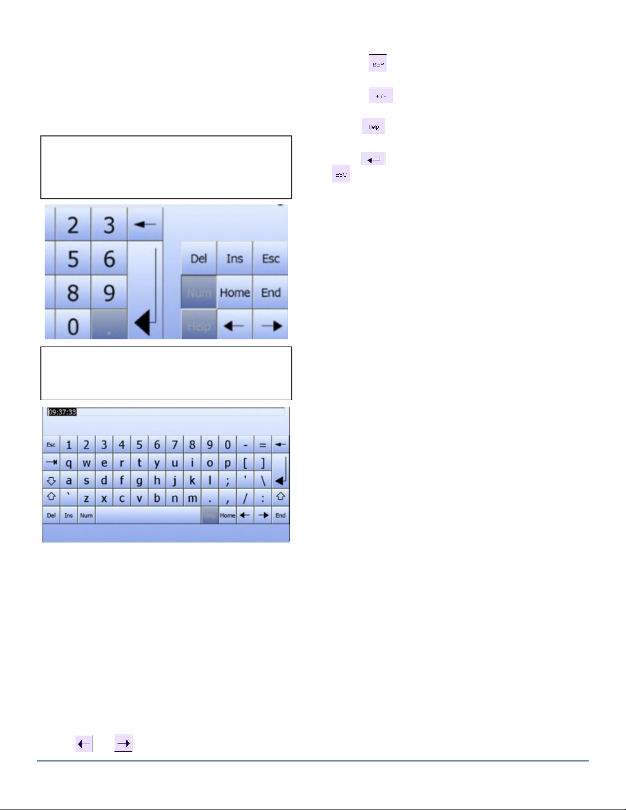
Numerical Entries: WhenyoutouchanIOeldon
theHMIdevicetouchscreenthatrequiresonlya
numericalentry(Password,Temperature,numberof
secondsetc.)thefollowingkeyboardwillappear.
Alpha/Numeric Entries:Whenyouarepromptedto
enteralphabecalandnumericaldata(ResinNames/
Numbers)thisscreenwillappear:
Proceed as follows:
1.TouchtherelevantIOeldonthescreen.
Thenumericalscreenkeyboardopensanddisplaysthe
current value.
2. Set the value.
Youcanonlyoperatekeyswhicharevisualizedin3Dfor-
mat.Thetypeofvaluetobeentereddetermineswhether
akeyisenabledordisabled.
Thefollowingoponsforenteringvaluesareavailable:
Thecurrentvalueisdeletedwhenyouentertherst
character. Enter the value again.
Use the and keystomovethecursorwithinthe
currentvalue.Youcannoweditthecharactersofthe
current value or add characters.
Use the keytodeletethecharactertotheleofthe
cursor.
Use the keytochangethesignofthevalue.
Select toviewtheinfotextoftheIOeld.
Select toconrmyourentriesorcancelthemwith
.
Bothaconsclosethescreenkeyboard.
15
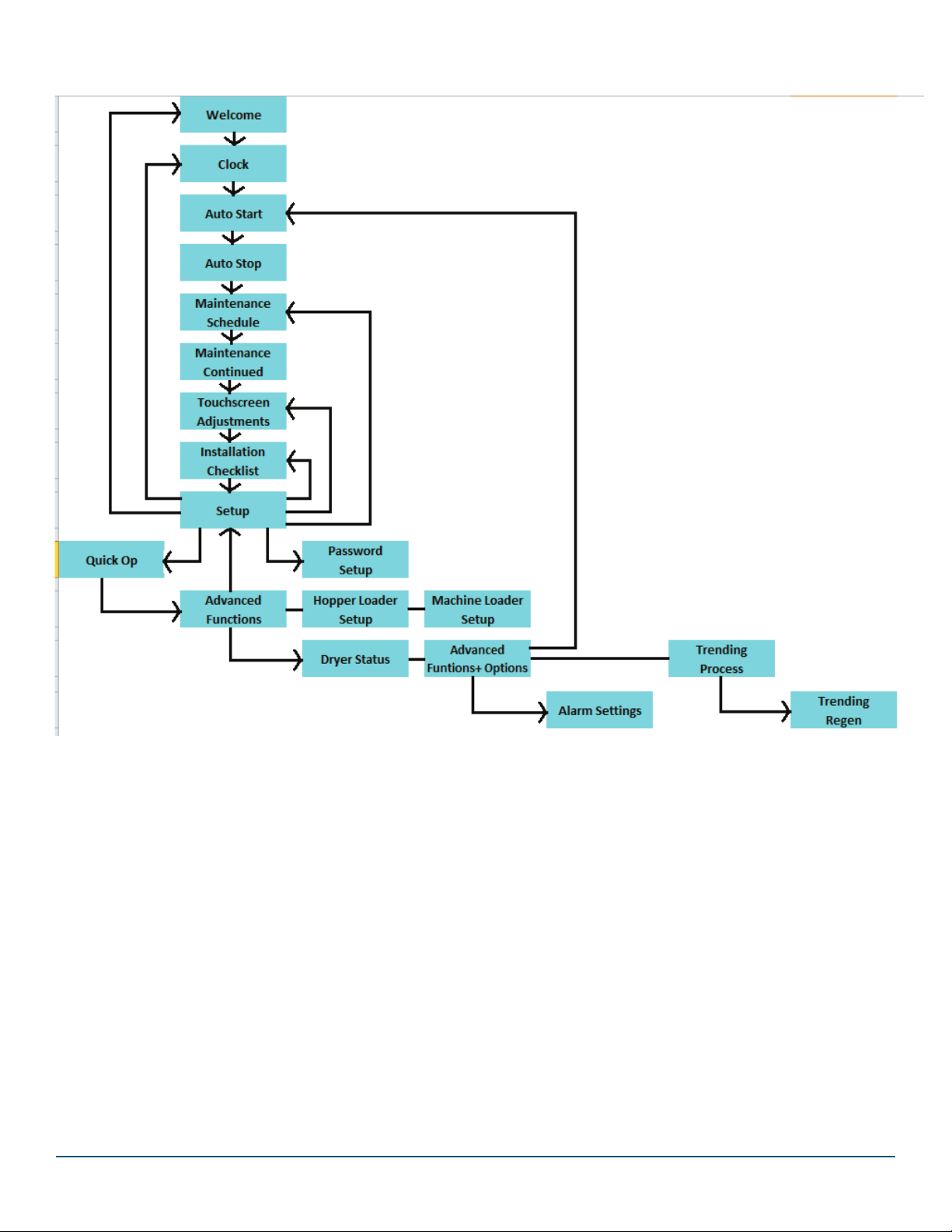
15.2 Screen Map
Forallprocessoroperaons.
16
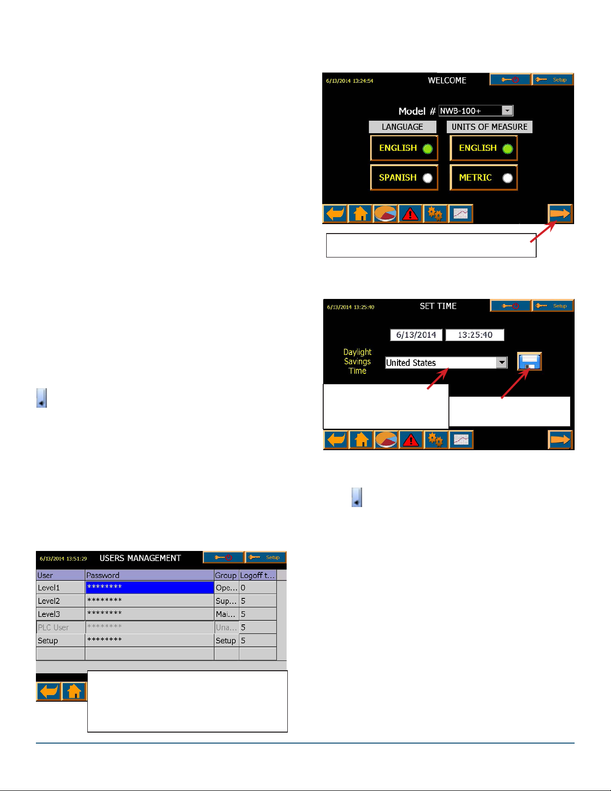
PressingMETRICwillchange°Fto°C.
Ifcorreconsarerequired,pressdateormebox.
16.0 INITIAL DRYER STARTUP
NOTE:Assurevoltage,conneconandphasingarecor-
rect,coolingwaterissupplied(fordryingover225°F)and
thermocoupleisinsertedinhopper.
ConnectmaterialsourcetoHopperLoader
TurnMainDisconnectSwitchto“ON”posion.
OnrststartyoushouldenterInformaonrequestedon
WELCOME screen.
NOTE: Usernamesetupandpassword4444isrequired
forinialsetup.Iftheproperlevelofpasswordprotec-
onhasnotbeenenteredpriortoaempngchanges,
thealpha/numericpasswordentrykeypadwillappear,
prompngtheusertoinputtheproperpasswordbefore
changescanbemade.
passwords.
UsernameandPasswordfactorydefaults(below)should
beupdatedtoensureproperaccess.
Todothat,double-tapthe********aereachLeveland
enterthenewpasswordonthealpha/numericscreen
thatwillappear.
Youwillbepromptedtoenterthepasswordtwice.Press
to return to USERS MANAGEMENT screen.
should be updated to ensure proper access.
Level1:1111(Operator)–Canchoosepre-setrecipeand
run it.
Level2:2222(ProduconSupervisor)
–level1pluscanchangerecipes,setclock&Auto
START/STOP
Level3:3333(Maintenance)Sameaslevel2
Setup: 4444RequiredforInialsetup
Setup: can change passwords for all levels
Level 3 can change Level 3 passwords
Level 2 can change Level 2 passwords
Level 1 can change Level 1 passwords
Press the Forward Arrow to TIME and DATE
Press the SAVE icon to save
themeanddate.
SelectNONEondrop-downif
DaylightSavingsTimedoes
notapply.
Analpha-numericscreenwillappear.Enterdateasxx/
xx/xxandmeasxx:xx:xxAMorPM.
Press aereachentryiscomplete.
TohavemefollowDaylightSavingsTimeinyour
geographicarea,chooseareafromdropdownandpress
SAVE.
Sengdateandmeassuresthatalarms
willhavecorrectdate&mestamp.

17
16.5 Auto Start/Stop (Level 2)
Press andtheAUTOSTARTscreenwillappear.
Choosedaysandentermesonnumericentryscreen
thatwillappear.Press aereachentryand to
enterAUTOSTOPdaysandmes.Entriesareoponal.
IfyoudonotwanttosetAutoStart/Stop,simplypress
IGNORE.
16.6 Maintenance Schedule (setup)
Press topageforwardtosetupmaintenance
schedule.
Itisimportantthateachofthesethingsarechecked
beforestarngthedryer
Choosethematerialcondionthatwillberunandthen
theappropriatemaintenancescheduleforeachtask.
NOTE:Performingmaintenanceonregularintervalswill
enhancedryerperformanceandlifeandminimizedown-
me.
PressingtheFORWARDbuononemoreme
willopentheSengsscreen(nextpage).

18
17.0 SETTINGS SCREEN (Anylevelcanview)
Thisscreenallowschangestobemadetopreviousscreensandalsoallowsadjustmentstobemadeto…
Alarm Setpoints User Passwords Advanced Opons
Screen Sengs
NOTE: You will go directly to
Quick Op screen (page 25) on all
future starts.
NOTE: From here on, these icons
will appear at the boom of every
screen.
To TRENDING Screen
To SETTINGS Screen Screen
To ALARMS Screen
To DRYER STATUS Screen
To QUICK OPS Screen
To Previous Screen Shown
(Anylevelcanview)
AsetupFuncon
Youmaywanttosetpasswordsforvariouspersonnelso
theyonlyhaveaccesstocertainfuncons.
Todothat,double-tapthe********aereachLeveland
enterthenewpasswordonthealpha/numericscreen
thatwillappear.
Youwillbepromptedtoenterthepasswordtwice.Press
to return to USERS MANAGEMENT screen.
Thesevariablesarepre-setatthefactorybutcanbe
changedbytheprocessor.Sengthevaluestooghtly
cancausenuisancealarms.

19
OverDryProteconisStandardonDC+modelsandcan
beacvatedformoisturesensiveresinslikenylon.
WaterSavercanbeacvatedwhenanexternalCooling
oilisemployed.
MoistureManagerisanoponthatmustbeorderedin
advance.
AlarmSengsarepre-setatNOVATECbutLevel3
personnelcanadjustthesengs.
NosecuritytoviewthesepagesbutLevel2andup
requiredtomakechanges
Youcancalibrate“Touch”,BrightnessandturnSoundON
orOFF.Ifthescreenisdirty,abuonallowsyoutoclean
itwithoutdisturbingthesengs.
Press toaccessQuickOpScreen.

20
18.0 DRYING MATERIAL
18.1 Quick Op Screen
NOTE:Assurevoltage,conneconandphasingare
correct,coolingwaterissupplied(fordryingover225°F)
andthermocoupleisinsertedinhopper.Connectmaterial
sourcetoHopperReceiver.TurnMainDisconnectSwitch
to“ON”posion.
ProcessTemperatureisfactorysetat160°F.
Presstemperaturebuon tochangetemperatureor
to access RESIN MENU and choose one of the
pre-set resins.
Press Green “ON” switchtostarttheProcessHeater
andBlowers.NotethatProcessHeatercanbeturned
OFForONusingbuons ontheQuickOpscreen.
NOTE: Do not turn the process heater and blowers
Press Hopper Receiver icon to access Hopper Loading
screenshownbelow.
18.2 Hopper Loader Setup
Presseachfunconandentervalueonnumericscreen.
Press aereachentry.Press on Hopper Loader
screen or onQuickOpscreentoaccessMachine
MountReceiverscreen(below).
NOTE: Values in Hopper and Machine Receiver screens
shouldbeadjustedtoopmalvaluesaerprocessingbegins.
Blowbackmustbespeciedwhenorderplaced.
theoverallme,inseconds,
thatmaterialenterstheconveyair
stream.ItisthemethestaonTvacuumvalve,andif
equipped,thematerialpurgevalve,areopen,allowing
materialow.Thissengisrelavetothesizeofthe
receiverandtheowcharacteriscsofthematerial.
Defaultmeis10seconds.Notethatonreceivers
equippedwithaproporoningvalvethisistheoverall
virginandregrindloadingme.
(ifequipped)isthemein
secondsthatthestaonTvalveremains
openwhilethematerialpurgevalveisclosedtomaterial
ow.Itallowsforthepurgingofmaterialfromthe
conveyinglineaertheLoadTimehasexpired.Thisme
isrelavetothedistancefromthematerialpurgevalve
tothereceiverandhowsmoothlythematerialows.
Defaultmeis10sec.
thisisthemethatthe
materialtakestofallfromthereceiver
intothedryinghopper,binormachineaerloadingis
completed.Thismeisdeterminedbyhowsmoothlyor
slowlythematerialowsbygravityfromthereceiver.
Defaultis10seconds.NOTE:DumpTimeshouldbeset
for10secondsormore.
Pulses –Forreceiversequippedwith
ltercleaningblowbackcapability,this
sengdeneshowmanyburstsofcompressedairare
releasedintothereceiverduringthedumpcycle,toclean
thelter.Requirespasswordlevel3tomakechanges.
Regrind Pct (Regrind Percent) –denes
whatproporonofvacuummewill
dedicated to loading regrind into the hopper. This value
isapercentageoftheFILLme.Forexample,iftheFILL
mewas10secondsandtheRegrindPercentwas40%,
thentheproporoningvalvewilldedicate4secondsto
llingregrindmaterial.Theproporoningvalvewillthen
allowvirginmaterialtobeloadedfortheremaining6
seconds.
worksinconjunconwith
the Regrind Percent. It tells the propor-
oningvalvehowmanymestoswitchbetweenloading
regrindmaterialandvirginmaterialwithinasinglell
cycle.Alayerconsistsofbotharegrindmaterialpartand
avirginmaterialpart.CAUTION:Thecalculatedload
meperlayershouldbe2secondsorgreatertomove
materialconsistently.Proporoningrepeatabilityim-
provesaseachlayer’sloadmeincreases.
This manual suits for next models
8
Table of contents
Other NovaTec Dryer manuals


Popular Dryer manuals by other brands

Kenmore
Kenmore 6972 - 700 7.5 cu. Ft. Capacity Electric... installation instructions

Whirlpool
Whirlpool WGD8300S Dimensions and installation information

Maytag
Maytag MGDE301Y user manual

LG
LG DLE3733 Specifications

Sharp
Sharp KD-NCB8S7PB9-EN user manual

World Dryer
World Dryer smartdri K4 series user manual


